You look down at the bed: the edges are scorched brown, the cut didn’t go all the way through, and a premium sheet of material is now scrap. Your instinct is to immediately lower the speed, crank up the power, or wipe the lens with a frantic urgency. Stop. That instinct is the fastest way to turn a minor calibration issue into a total system realignment. When a machine that was cutting perfectly yesterday suddenly fails today, you don't need a screwdriver yet—you need a triage protocol.
Whether you are running a compact workshop system or an industrial setup like a Single Table Fiber Laser Cutting Machine or a high-throughput Double Table Fiber Laser Cutting Machine, the principles of systematic troubleshooting remain the same: slow down, observe, and verify before adjusting.
Stop the Machine: A 5-Minute Triage Before You Waste More Material
Before you touch a single mirror or adjust a parameter, you must rule out the environmental factors that kill consistency. This triage takes less than five minutes, requires no tools, and saves you from "fixing" things that aren't broken.
The "Is It Safe?" Check: Fire, Water Flow, and Air Assist
Your first goal is to confirm that the machine’s life-support systems are functioning. If these basics are off, no amount of optical alignment will fix the cut quality.
Fire and Smoke Watch the cut for ten seconds. You are looking for the difference between ablation and combustion. A proper laser cut produces instantaneous sparks or a bright plasma flash as it vaporizes material. If you see a lazy, yellow flame that dances along the kerf or persists after the head moves on, stop immediately. This indicates a lack of air assist or a material that is melting rather than vaporizing. Furthermore, check the exhaust smoke. If it is significantly darker or thicker than usual, the extraction system may be clogged, causing smoke to diffuse the laser beam before it hits the material.
Water Flow (CO₂ Systems) Don't just listen for the hum of the chiller; look at the numbers. For most glass-tube CO₂ lasers, the thermal "sweet spot" is tight—typically between 18°C and 22°C. If your water is running at 28°C, your tube is losing significant power efficiency. Conversely, if the water is too cold, you risk condensation on the tube or thermal shock cracks. Verify there are no bubbles in the tube, which create hot spots, and ensure the return line has strong flow. If the flow is weak, a kinked hose or failing pump will kill your tube long before you finish troubleshooting the cut.
Air Assist Air does more than prevent fire; it clears the optical path. Place your hand under the nozzle (with the laser disarmed) and trigger the air. You should feel a sharp, continuous jet, not a gentle breeze. If you use a shop compressor, check the water trap and oil separator immediately. A compressor that is spitting moisture or oil will coat your focusing lens in seconds, diffusing the beam and cooking the debris onto the glass. If the air is weak, the laser energy is wasted fighting through a cloud of smoke and debris rather than cutting the material.
Don't Change Everything at Once: The Rule of Single Variable Testing
When a machine drifts out of spec, the most dangerous operator is the one who changes the speed, wipes the mirrors, and adjusts the focal height all at once. If the machine starts working again, you won't know why. If it gets worse, you won't know which adjustment caused the new problem.
Treat troubleshooting like a controlled experiment. You are dealing with a coupled system where power, speed, focus, and material density interact.
- Isolate the Symptom: Define the failure clearly. Is it "not cutting through on the bottom right quadrant" or "jagged edges everywhere"?
- Prioritize the Variables: Do not start by realigning mirrors—that is a last resort. Start with the easiest, most likely culprits: Lens cleanliness > Focus height > Material flatness > Speed/Power settings.
- The "One Change" Protocol: Change one variable. Run a test. Record the result. For example, if you suspect the lens is dirty, clean it, then run the test again with the exact same file and material. If the quality doesn't improve, the lens wasn't the issue. Move to the next variable.
A Known-Good Test File: Separating Machine Problems from Design Problems
The most common "ghost" in laser cutting is a corrupted or poorly designed file masquerading as a hardware failure. To separate the two, you need a "Known-Good" test file.
This is not a random square you draw on the fly. This is a standardized file—a "Golden Sample"—that has been proven to cut perfectly on this specific machine with this specific material type. It should include:
- A Power/Speed Grid: A small matrix (e.g., 3x4 squares) testing the edge of your material's settings.
- Geometric Variety: Sharp corners to test acceleration control, circles to check for backlash, and a long straight line to reveal beam divergence.
- Frozen Parameters: The speed, power, and layer settings must never be changed.
How to use it: When your current project fails, pause the job and load the Known-Good file. Run it on a scrap piece of the same material.
- Scenario A: The Known-Good file cuts perfectly.
- Diagnosis: Your machine is fine. The problem is in your design file. Look for duplicate vectors (cutting twice in one spot), unclosed paths, or incorrect layer parameters in your software.
- Scenario B: The Known-Good file fails (scorched edges, uncut sections).
- Diagnosis: The issue is physical. You have now confirmed that the problem lies with the optics, the tube power, the alignment, or the material batch itself.
By relying on a baseline, you stop guessing and start solving the actual problem.
Read the Edge: What Your Failed Cut Is Trying to Tell You
Most operators treat laser troubleshooting like a slot machine. When a cut fails, they start pulling levers randomly—increasing power, slowing down speed, changing frequency—hoping for a jackpot. This approach is not only inefficient; it destroys the evidence. The edge of a failed cut is a forensic record. It captures the exact interaction between your optics, your mechanics, and the thermodynamics of the material. Before you touch a single parameter, you must learn to read the striations and deformities of the kerf. They are not random errors; they are specific symptoms.
If the Edge is Slanted: Diagnosing Beam Perpendicularity vs. Mechanical Tilt
A common and frustrating defect is the slanted edge, where the top of the cut is dimensionally accurate, but the bottom has drifted, resulting in a part that is a parallelogram rather than a rectangle. The immediate instinct is to blame the beam alignment, assuming the laser is entering the material at an angle. However, a slanted edge is just as likely to be caused by the material or the bed itself.
To distinguish between optical misalignment and mechanical tilt, perform the "Flip Test." Cut a straight line on your material. Then, flip the material sheet over (180 degrees) and cut a second line parallel to the first in the same area. Compare the slant of the two cuts.
If the direction of the slant flips with the material (e.g., the first cut slanted left, the second cut slanted right relative to the bed), the issue is mechanical. Your material is warped, your honeycomb bed is uneven, or the sheet is not sitting flat. The laser is perpendicular to gravity, but the workpiece is not.
If the direction of the slant remains constant relative to the machine coordinates (e.g., both cuts slant toward the +X direction regardless of how the material is oriented), the issue is optical. The laser head is not perpendicular to the gantry, or the beam path is entering the focusing lens off-center. When a beam hits the lens off-center, it exits at an angle. This creates an asymmetric energy density profile: one side of the kerf receives direct, intense energy (cutting straight), while the other side receives the decaying edge of the Gaussian beam, resulting in a tapered or slanted wall.
If the Cut is Serrated or "Saw-Toothed": Identifying Vibration and Loose Belts
When the edge of a straight cut exhibits a rhythmic, serrated texture—resembling the edge of a coin or a saw blade—the laser source is rarely to blame. This "rippling" effect is the signature of mechanical instability. The laser is pulsing correctly, but the gantry carrying it is oscillating.
To pinpoint the source, analyze the regularity of the serrations. If the ripples appear at a fixed, consistent pitch (e.g., every 2mm), you are likely looking at a gearing or transmission issue. This often points to a loose belt where the teeth are not engaging smoothly with the pulley, or a stepper motor resonance issue where the micro-stepping resolution is mismatched with the mechanical load. The machine is "cogging" rather than gliding.
If the serrations are irregular or appear only at specific speeds, the culprit is likely resonance vibration. Every machine frame has a natural frequency. If your acceleration settings are too aggressive for the frame's rigidity, the gantry will vibrate like a plucked guitar string during motion.
A critical diagnostic detail: Look at where the serration occurs on the cut face. If the serration is severe at the top of the edge (the entry point), the vibration is mechanical—the nozzle itself is shaking. If the top edge is smooth but the bottom edge is serrated or wavy, this is often a fluid dynamics issue known as "drag." It suggests the gas pressure is too low to evacuate the molten material, or the cutting speed is slightly too fast, causing the melt flow to become turbulent as it exits the bottom of the kerf.
If Corners are Burned but Lines are Fine: The Acceleration/Min-Power Mismatch
This is the classic symptom of a dynamic control failure: the long straight lines of your part are crisp and clean, but every 90-degree corner is blown out, melted, or blackened.
This occurs because of the physics of motion control. To turn a sharp corner, the laser head must decelerate to a near-stop before changing direction. If the laser power remains constant while the speed drops, the energy density (heat input per unit of area) skyrockets at the corner. You are essentially dwelling in one spot with full power.
The solution lies in the Min Power (or Corner Power) setting in your controller. The laser power should dynamically scale with the velocity of the head. When the head slows down for a corner, the power should drop proportionally.
If your corners are burning, your Min Power is set too high—the laser is still firing at cutting strength even when the machine is barely moving. Conversely, if you adjust the Min Power and the corners become clean but the machine fails to cut through the material only at the corners, your Min Power is too low. The goal is to match the deceleration curve: as velocity drops by 50%, power output should drop sufficiently to maintain consistent heat input, preventing the heat-affected zone (HAZ) from expanding at the vertices.

If the Cut Doesn't Penetrate: Distinguishing Power Loss from Focus Drift
When a laser fails to cut through the material, operators often assume the tube is dying or the power supply is failing. However, "not cutting through" has two distinct visual profiles that allow you to distinguish between a lack of photon power and a lack of optical focus.
Case A: Focus Drift. If the cut fails to penetrate but the kerf (the width of the cut) looks unusually wide and the top edges are rounded or melted over, the issue is focus. The energy is there, but it is dispersed over a large area rather than concentrated into a tight spot. The beam is hitting the material "out of focus," dumping heat into the surface without the intensity required to pierce deep. This is often caused by a loose lens nut, a shifted Z-axis, or a warped bed.
Case B: Power Starvation. If the kerf is narrow and the top edge is sharp, but the cut simply stops halfway down or leaves a messy, dross-filled connection at the bottom, this indicates a lack of raw power or gas pressure. The beam is focused correctly (hence the narrow kerf), but it lacks the amplitude to eject the material through the full thickness.
To confirm this without expensive metering equipment, perform a Step Focus Test. Take a piece of scrap material and run a series of short lines, adjusting the focus (Z-height) up or down by 0.5mm for each line. If one of those lines cuts through cleanly, your laser source is healthy, and your focus was simply set wrong. If none of the lines penetrate—regardless of the focal height—and the cut face looks rough and starved across all settings, you are dealing with power degradation or severe optical contamination.
"It Powers On, But the Cuts Are Terrible": Diagnosing Beam & Optics
If the machine powers up, homes correctly, and fires the laser, but the resulting cuts are charred, incomplete, or require significantly slower speeds than usual, you are facing the most common frustration in laser operation: efficiency loss.
The machine is not "broken" in the binary sense, but the energy leaving the tube is not reaching the material with sufficient density. This is almost exclusively an issue of the optical train or the beam generation source. Before you start replacing expensive components, you must trace the energy loss systematically.
The "Clean" Lens Trap: Why Your Optics Are Still Killing Power
The most dangerous assumption in laser troubleshooting is: "I looked at the lens and it looks clean, so the problem must be elsewhere."
Visual inspection under ambient room lighting is insufficient for diagnosing optical failure. A lens does not need to be cracked or visibly opaque to destroy your cutting power. The culprit is often absorption, not obstruction.
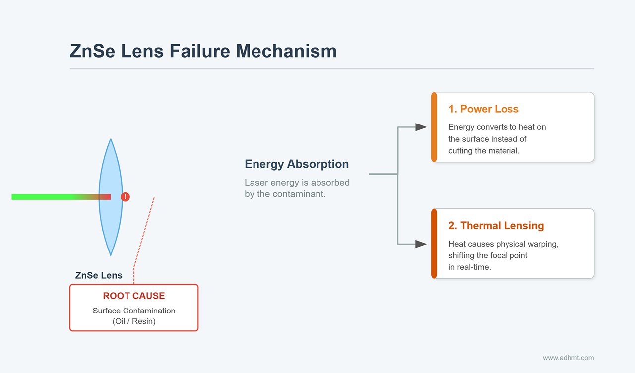
ZnSe (Zinc Selenide) lenses work by being transparent to infrared light. If a lens has a microscopic film of oil, resin vapor, or improper cleaning residue, it begins to absorb a percentage of the laser energy rather than passing it through. This absorption creates two compounded problems:
- Power Loss: The energy is turned into heat at the lens surface instead of cutting the material.
- Thermal Lensing: As the lens heats up from absorption, it physically warps. This changes its curvature and refractive index in real-time. You might start a cut with a perfect focal point, but three seconds later, the focus has shifted 2mm upwards, ruining the cut depth.
To properly diagnose this, remove the lens and hold it against a dark background under a bright, directed light (like a smartphone flash). You are looking for a cloudy haze or "oil slick" diffraction that is invisible under standard overhead lights. If the lens is physically intact but performance is poor, perform a "back-to-back" test with a brand new lens. If the new lens restores power, your old lens—despite looking "clean"—has suffered coating degradation or thermal fatigue and must be discarded.
Do not neglect the mirrors. A mirror that is 98% reflective works fine; a mirror that has degraded to 90% reflective due to oxidation or smoke residue will cause a massive drop in power by the time the beam hits the third mirror.
The Ramp Test: Finding True Focal Depth When Your Gauge Tool Lies
Most laser cutters come with a small acrylic or aluminum step-gauge block for setting the focus height. You should regard this tool as a rough estimate, not a measurement of truth.
The focal length of a lens (e.g., 2 inches / 50.8mm) is a theoretical distance from the center of the lens to the focal point. However, the actual focal point relative to your nozzle tip depends on where the lens sits inside the tube, the thickness of the washer, and the manufacturing tolerance of the lens itself (which can vary by ±1mm). Relying solely on the gauge block often leads to focusing slightly above or below the material, drastically reducing energy density.
To find the actual optimal focus, you must perform a Ramp Test:
- Place a long scrap piece of wood (at least 10 inches) on the honeycomb bed.
- Prop up one end of the wood so it sits on a slope (a "ramp"). The low end should be lower than your estimated focus, and the high end should be higher.
- Run a straight vector line cut down the center of the wood at a speed and power that barely marks the surface.
- The result will be a line that varies in width. It will look like an elongated hourglass.
- Find the spot on the wood where the line is the thinnest. This is your true focal point.
- Move the laser head over that specific spot and measure the distance from the nozzle to the wood.
Cut a new gauge block to this exact dimension. This test eliminates all variables and shows you exactly where the beam waist is tightest.
Tube vs. Supply: Reading the Ammeter and the Color of the Plasma
If your optics are pristine and your focus is perfect, but the machine still struggles to cut through material it handled easily last week, you must determine if the Laser Power Supply Unit (LPSU) is failing to send power, or if the Laser Tube is failing to convert it.
The primary diagnostic tool here is an analog milliammeter (mA meter). Many machines have one built-in; if yours does not, installing one in series with the cathode (negative) return line is a critical upgrade.
Scenario A: The Ammeter Reads LowIf you command the machine to fire at 80% power, but the ammeter only rises to 8mA (when it should be closer to 20mA+ depending on your tube rating), the issue is likely the Power Supply. The LPSU is failing to generate the necessary high voltage current. This can also result from a failing flyback transformer inside the supply.
Scenario B: The Ammeter Reads Normal, but Power is LowIf the meter correctly shows 24mA, but the beam barely marks the wood, the issue is the Laser Tube. The tube is drawing the correct electrical current but has lost its chemical efficiency. The gas mixture (CO2, Nitrogen, Helium) may have depleted or decomposed.
The Color CheckYou can confirm tube health by observing the color of the plasma beam inside the glass tube while it fires (do this safely through the polycarbonate window; never bypass safety interlocks).
- Bright Purple/Pink: Healthy ionization. The gas mix is correct.
- White/Pale: The gas is degrading. The tube is near the end of its life.
- Glowing Anode (Metal Ring): If the metal ring at the end of the tube glows orange or red, the tube is likely dead or experiencing severe cooling failure.
The "Lens Reinstalled Backwards" Check (More Common Than You'd Admit)
It happens to seasoned engineers and novices alike. You take the lens out for a routine cleaning, get distracted, and drop it back into the nozzle. Suddenly, the machine cuts with a wide, sloppy kerf and cannot penetrate thick material.
CO2 laser lenses are Plano-Convex. They have one flat side and one curved (convex) side. The physics of these lenses dictates that the curved side must face the laser beam (up), and the flat side must face the material (down).
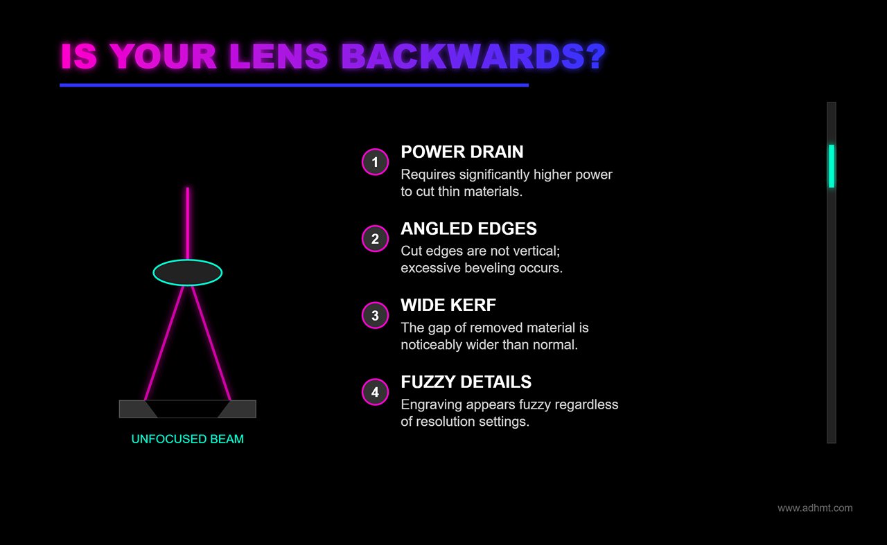
When a lens is installed convex-side down (backwards), it introduces Spherical Aberration. Instead of converging the light rays to a single, tight point, the rays focus at different distances along the Z-axis. This creates a "blurry" focal point with a much larger diameter.
Symptoms of a backwards lens:
- You have to increase power significantly to cut thin materials.
- The cut edges are not vertical (excessive bevel).
- The kerf (width of material removed) is noticeably wider than usual.
- Engraving looks fuzzy regardless of resolution settings.
If you are troubleshooting a sudden drop in cut quality immediately after maintenance, stop checking the electronics. Open the nozzle and flip the lens. The "bumps" should always face the incoming beam.
Cuts Look Like Seismograph Readings: Motion and Mechanical Failures
If you have meticulously aligned your mirrors and cleaned your lens, yet your straight cuts still ripple like a lie detector test during a perjury interrogation, your issue is no longer optical. It is mechanical. The beam is perfect, but the vessel carrying it is unstable.
Most operators instinctively react to wavy lines by tightening the belts until they simulate a piano wire. This is the single most common mistake in mechanical troubleshooting. Over-tightening does not fix resolution; it introduces radial load that overheats stepper motor bearings, warps the gantry, and eventually causes the very "skipped steps" you are trying to prevent. To resolve motion artifacts, you must stop guessing with your fingers and start measuring with physics.
The "Guitar String" Tension Test: Tuning Belts Without Over-Stressing Motors
The "finger pinch" test—squeezing the belt to see if it feels tight—is fundamentally flawed. It is subjective, inconsistent, and heavily influenced by the operator's grip strength and the ambient temperature. To eliminate jagged edges, you need a quantifiable, repeatable metric.
Treat your timing belts like instrument strings. The frequency at which a belt vibrates is directly related to its tension (T) and span length (L). By measuring the acoustic frequency, you can tune the X and Y axes to identical tensions without overloading the motors.
The Frequency Protocol:
- Download a Spectrum Analyzer: Install a mobile app like "Spectroid" (Android) or "LP Tension Meter" (iOS). You need a tool that visualizes peak audio frequency.
- Isolate the Span: Move the laser head to the far end of the axis to expose the longest possible section of the belt (typically 300–400mm on a standard CO2 laser).
- The Pluck: Pluck the center of the belt span sharply, exactly like a guitar string.
- The Reading: Watch the app for the dominant frequency peak. Ignore the lower harmonics.
For a standard 6mm wide GT2 belt, the "Goldilocks zone" is typically between 110Hz and 140Hz.
If the reading is below 110Hz, the belt is too slack, leading to hysteresis and wavy corners. If it exceeds 150Hz, you are crushing the motor shaft bearings. Adjust the tensioner screw by quarter-turns, replucking after every adjustment. Note that new belts will stretch during the first 100 hours of operation; if you install a fresh belt, tune it to the higher end (140Hz) and re-check it after a week of production.
Why Perfect Circles Turn Into Ovals: Checking Backlash and Grub Screws
When a 20mm circle cuts as a 19.5mm x 20.2mm oval, or when the start and end points of a cut fail to meet, you are dealing with backlash. This is mechanical "slop"—the tiny delay between the motor turning and the gantry actually moving. This error accumulates every time the machine reverses direction.
You can diagnose the source of the mechanical failure by analyzing the geometry of the distortion. If the oval is flattened along the X-axis, your X-axis drive train has play. If the oval is diagonal, you likely have play in both axes or a racking gantry.
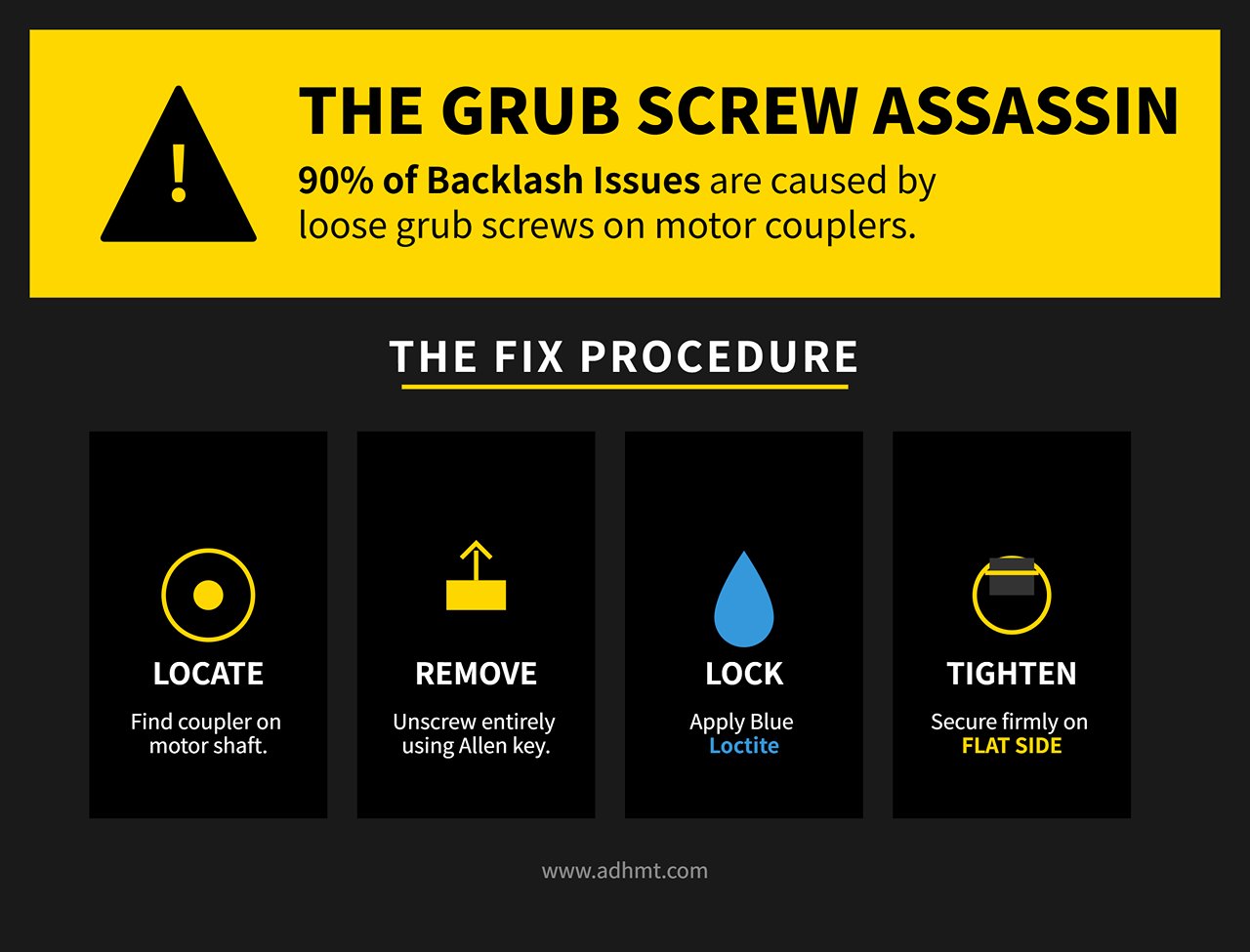
The "Grub Screw Assassin: Before you touch software compensation, check the grub screws (set screws) on the motor couplers and pulleys. This is the culprit in 90% of backlash cases. A grub screw can look tight but slip under high-torque directional changes.
- Locate the coupler connecting the stepper motor to the drive shaft.
- Use an Allen key to remove the grub screw entirely.
- Apply Blue Loctite (threadlocker). Do not skip this. The vibration of a laser cutter will inevitably loosen dry screws.
- Re-tighten firmly against the flat side of the D-shaft.
The Dial Indicator Verification:To confirm the issue is resolved, clamp a dial indicator to the machine bed with the probe touching the laser head nozzle. Zero the indicator. Command the software to move the head 10mm away, then 10mm back. The indicator should return to exactly zero. If it reads 0.05mm or greater, you still have mechanical play—likely a worn belt tooth or a loose pulley bore. Only apply software "Backlash Compensation" if the mechanical error is below 0.02mm.
That Grinding Sound You Ignored: Skipped Steps and Acceleration Limits
A laser cutter should hum; it should never grind, crunch, or click. A grinding noise accompanied by a layer shift (where the cut suddenly jumps 5mm to the left) indicates skipped steps. The controller sent a pulse to the motor, but the motor did not have enough torque to execute the move.
This is rarely a broken motor. It is almost always a battle between Acceleration and Current.
The Acceleration Ceiling: Operators often confuse speed with acceleration. You can run high speeds (500mm/s) with low acceleration, but high acceleration (3000mm/s²) demands massive torque. If your machine skips steps during complex engraving or direction changes:
- Open your machine settings (e.g., Vendor Settings in LightBurn).
- Find the Acceleration values for X and Y.
- Cut them in half. If you are at 2000mm/s², drop to 1000mm/s².
- Run a test. If the grinding stops, your motors were being pushed beyond their magnetic holding torque.
Current and Resonance: If the acceleration is low and the machine still "stalls" with a buzzing noise, check the stepper driver current. A driver set too low cannot push the motor through friction patches on the rails. However, a driver set too high causes the motor to overheat and lose magnetism.
- The Touch Test: After a 30-minute run, touch the stepper motors. They should be warm (40-50°C), not burning hot (>60°C). If they are cold and skipping, increase the amperage on the driver slightly. If they are burning, dial it back.
Finally, verify that your rails are lubricated. A dry linear rail increases static friction, requiring more force to initiate movement. No amount of tuning will fix a machine that is fighting against its own rusted bearings.
No Laser Fire at All: Isolating Electrical vs. Optical Failure
The most expensive mistake operators make when a laser refuses to fire is assuming the tube is dead. In reality, a glass CO2 laser tube is rarely the first component to fail silently. When a tube dies, it usually goes out fighting—fading power over weeks or arcing visibly. If your machine was cutting perfectly yesterday and refuses to fire today, the culprit is almost certainly an electrical interruption, not an optical failure.
Before you browse for replacement tubes, you must determine if the system is physically broken or simply "safety-locked." Most "dead" machines are actually functioning correctly: they are detecting a fault condition and deliberately cutting power to the laser source to prevent damage.
Interlocks, Sensors, and Water Alarms That Masquerade as Dead Lasers
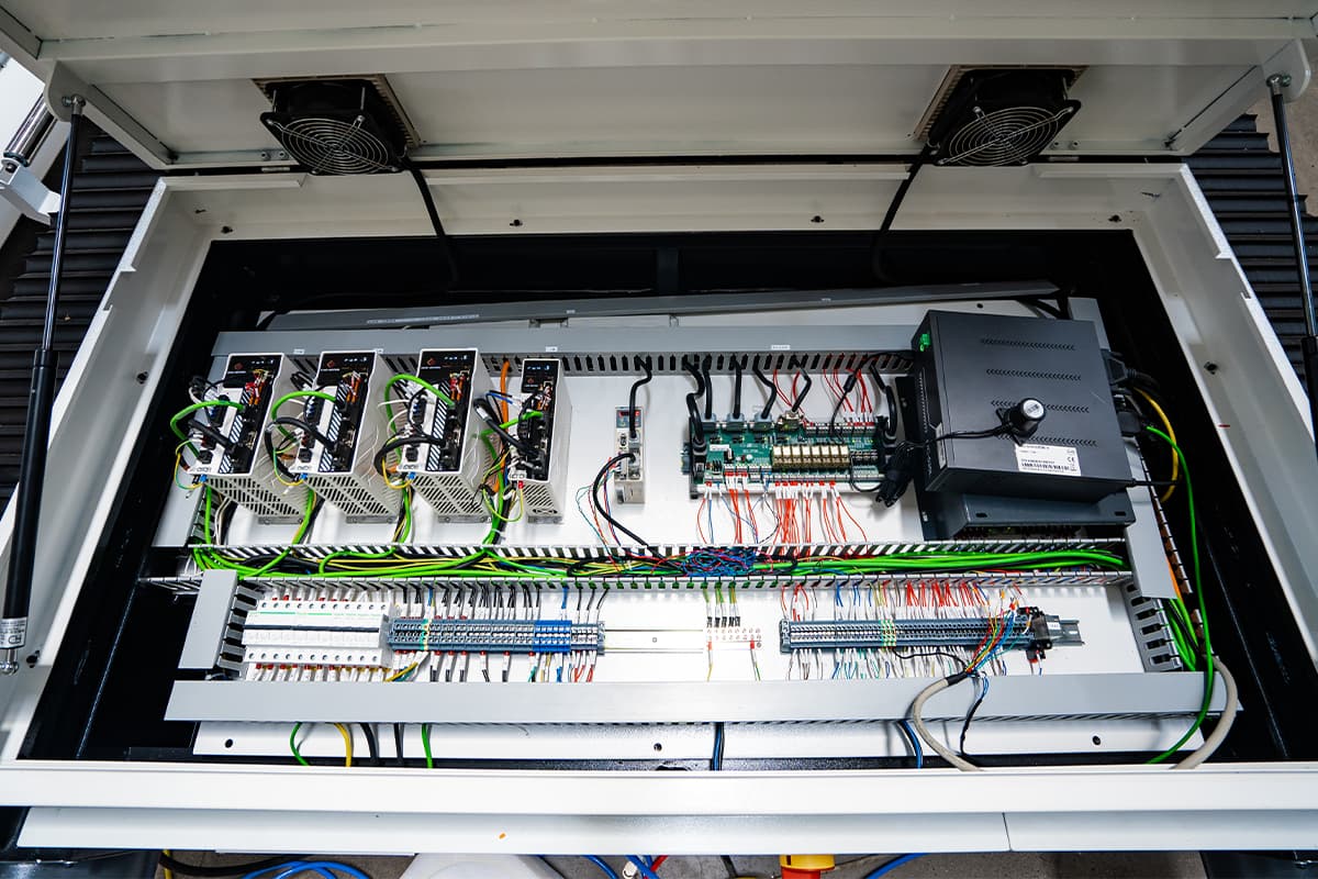
Ninety percent of "no-fire" scenarios are caused by a safety loop doing its job too well. The laser power supply unit (LPSU) requires a closed circuit on its protection terminals—often labeled WP (Water Protection) and G (Ground)—before it will release high voltage. If this circuit opens for a fraction of a second, the laser cuts out instantly.
The water flow sensor is the most common offender. These sensors often rely on a magnetic plunger that can become stuck due to algae buildup or debris in the cooling loop. If your chiller is running but the laser won't fire, the sensor may not be reporting the flow to the controller. Similarly, magnetic door interlocks on the chassis lid can shift over time. A misalignment of just two millimeters can break the circuit, leaving the machine in a permanent "lid open" state.
To rule these out, locate the WP and G terminals on your power supply. With the machine on but the laser disabled, look for a status LED on the power supply (often labeled "LASER" or "WP"). If it is off, the protection loop is open. You can temporarily diagnose this by placing a jumper wire directly between the WP and G terminals on the power supply, bypassing the external sensors entirely. If the laser fires with the jumper in place, your tube and power supply are healthy; the fault lies in a sensor, a loose wire in the drag chain, or the chiller alarm output.
Warning: This jumper test is for diagnosis only. Never operate a machine with safety interlocks permanently bypassed.
The Pulse Test: Tracing the Signal from Controller to PSU to Tube
Once you have confirmed the safety loop is closed, you need to locate where the "fire" signal is dying. The signal path moves from the Controller (Motherboard) → Low Voltage Wiring → Power Supply → High Voltage Wiring → Tube. You can isolate the failure point by testing these components in reverse order using the "Pulse" or "Test" buttons.
Start at the Power Supply Unit itself. Almost all CO2 laser power supplies feature a small red button labeled "TEST." Pressing this bypasses the controller and the software entirely, forcing the PSU to send a pre-set current to the tube.
Scenario A: The Tube Fires on PSU Test.**If pressing the button on the power supply creates a beam (or a plasma arc in the tube), your tube and power supply are functional. The problem is upstream. The controller is sending a signal that isn't reaching the PSU, or the controller itself is failing to generate the signal. Check the thin signal wires (TTL/PWM) connecting the mainboard to the PSU.
Scenario B: No Fire on PSU Test.**If the PSU test button produces nothing, the issue is within the high-voltage "engine room." You have narrowed the culprit down to the PSU, the high-voltage lines, or the tube itself.
At this stage, observe the tube while pressing the test button. You are looking for a plasma glow. A healthy tube glows pink or violet. If you see a pale white or very faint glow, the gas mixture has likely leaked or degraded. If you see no glow at all, but the PSU fan is spinning, the power supply may be failing to generate the ignition voltage required to strike the arc.
Power Supply Red Flags You Can Spot Without a Multimeter
You do not always need a multimeter to diagnose a dying power supply; the unit often gives physical clues of its demise. The most obvious indicator is the cooling fan. The fan on the LPSU is usually wired directly to the internal 220V/110V rail. If the fan is not spinning, the unit is likely not receiving mains power (check the fuse) or the internal bridge rectifier has blown.
If the fan spins but the laser won't fire, listen closely to the unit while pressing the test button. A failing flyback transformer—the large black coil responsible for stepping up the voltage—will often emit a distinct hissing or crackling sound. This indicates internal arcing, where the high voltage is jumping to the casing rather than traveling to the tube.
Finally, inspect the "L-ON" or "Laser" LED on the power supply during a test pulse.
- LED lights up, but no beam: The logic circuit is working, but the high-voltage output stage is dead. This usually points to a blown flyback transformer.
- LED does not light up: The power supply isn't even trying to fire. If you have already jumped the WP/Ground terminals, this indicates a failure on the input logic board of the PSU.
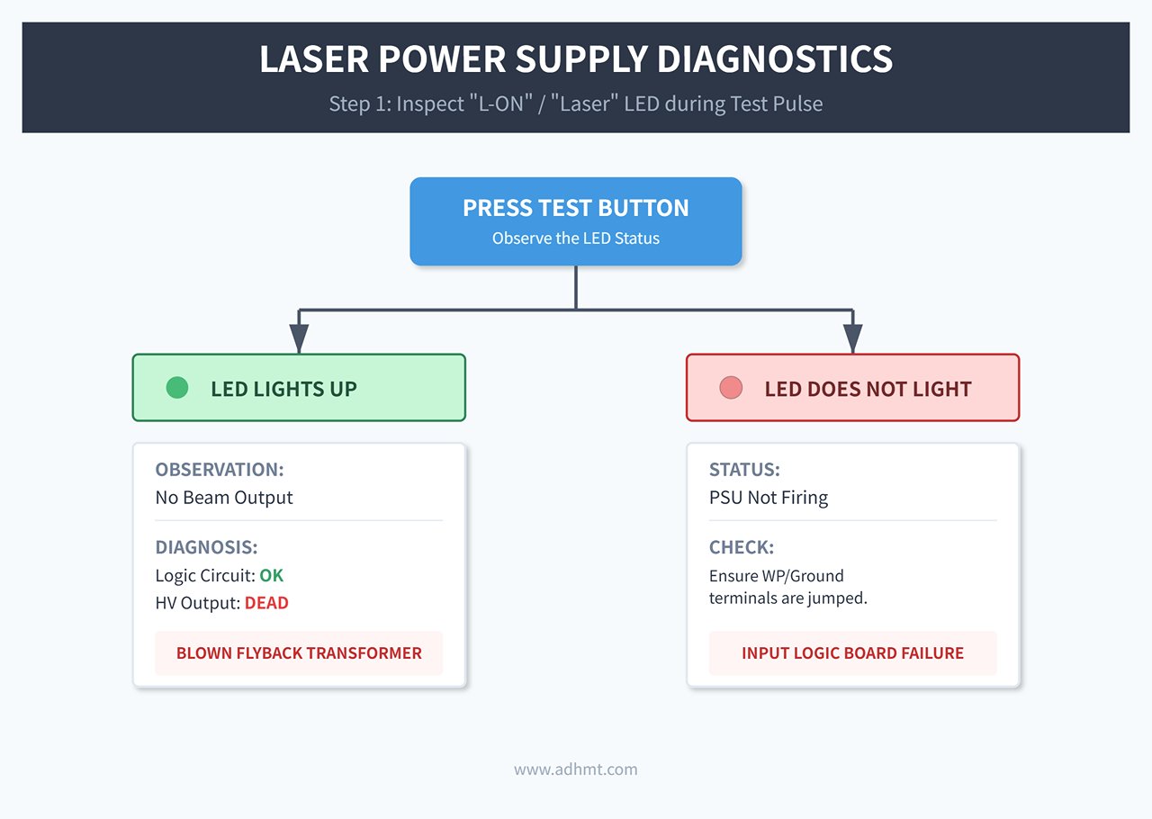
Visual inspection can also save you time. Look through the vents of the power supply casing. If you see any bulging capacitors (the tops should be flat, not domed) or smell the sharp tang of ozone or burnt epoxy, the power supply has suffered a catastrophic component failure and requires replacement.
"It Was Fine Yesterday": Problems That Appear Right After Maintenance
The most frustrating moment in laser operation isn't when a part breaks due to age; it is when performance drops immediately after you tried to take care of the machine. You spent the afternoon cleaning optics, greasing rails, and tightening belts, only to find your next cut has charred edges or fails to penetrate.
The instinct is to blame a sudden component failure, like a dying tube or power supply. However, coincidence is rare in industrial troubleshooting. If the machine worked before you touched it, the variable is the maintenance itself. The issue is rarely that you didn't clean enough; it is usually that the cleaning process introduced microscopic misalignments or invisible residues that the naked eye ignores but the laser beam cannot.
What Goes Wrong After Optics Cleaning (And How to Reverse It)
If power drops by 15-20% immediately after cleaning, do not scrub the mirrors again. You are likely dealing with "cleaning haze" or incorrect reassembly, not dirt.
The most common invisible culprit is rapid evaporation of high-purity Isopropyl Alcohol (IPA). When IPA evaporates too quickly in a humid environment, it can leave a thin film of moisture or dissolved oils from the lens mount. To the eye, the mirror looks pristine. To a laser beam, this film acts as a diffuser, scattering energy before it reaches the material.
The Diagnostic:Perform the "Oblique Flashlight Test." Shine a bright LED flashlight across the surface of the lens or mirror at a shallow angle (15-30 degrees). If you see a rainbow sheen, a milky haze, or a specific circular smudge, you have residue.
The Fix:
- Switch Solvents: Use acetone for the final wipe on glass or silicon mirrors (never on plastic lenses) to strip the IPA haze.
- The Drop-and-Drag Method: Do not scrub. Place a lens tissue wet with solvent on the optic and drag it slowly across. This prevents the "swirls" caused by circular wiping.
- Check Lens Orientation: A classic post-maintenance error is reinstalling the focus lens upside down. For standard Plano-Convex lenses, the convex (curved) side must face up toward the laser source. If the flat side faces up, the focal point shifts dramatically, and the beam will not converge correctly, resulting in wide, weak cuts regardless of power settings.
The Mirror Alignment Sequence Everyone Skips
If your machine cuts perfectly in the top-left corner (near the tube) but fails to cut through in the bottom-right, you likely bumped a mirror during cleaning. Even the pressure of a cotton swab can shift a mirror mount by a fraction of a millimeter. Over the distance of the gantry, that fraction becomes a missed target.
Most operators fix this by adjusting the beam to hit the center of the mirror. This is wrong.
Center alignment is secondary to parallel alignment. If the beam hits the center of Mirror 3 but travels at a 1-degree angle relative to the X-axis rail, the beam will clip the nozzle tip when the head moves to the far side of the bed.
The Correct Sequence (The "Near/Far" Method):**You must align the beam to be parallel to the axis of travel, not just to the center of the optic.
- Tube to Mirror 1: Ensure the beam hits the center of Mirror 1.
- Mirror 1 to Mirror 2 (Y-Axis): Place a target on Mirror 2. Pulse the laser with the gantry close to Mirror 1 (Near Field). Mark the spot. Move the gantry to the back of the machine (Far Field) and pulse again.
- The Goal: The two dots must overlap perfectly. They do not need to be in the center of the mirror yet; they just need to be on top of each other.
- The Adjustment: Adjust Mirror 1 screws until the Near and Far dots merge. Only then do you adjust the entire mount to center the beam.
3. Mirror 2 to Mirror 3 (X-Axis): Repeat the Near/Far process. Pulse with the head close to Mirror 2, then move the head to the furthest point away. Adjust Mirror 2 until the dots overlap.
If you skip the Far Field verification, you are aligning the laser to a single point in space, not a reliable path across the table.
Settings You Changed Three Days Ago and Forgot About
If the optics are clean and the alignment is parallel, the "maintenance" issue is likely a "memory" issue. It is common to tweak a software setting for a specific, difficult job—like cutting thick acrylic or engraving glass—and forget to revert it. When you return to standard production, the machine behaves erratically.
The "Min Power" Trap:**In software like LightBurn or RDWorks, check your Min Power setting. If you raised this to 40-50% for a high-speed engraving job three days ago, your laser is now blasting corners during slow cutting moves. This manifests as burnt corners on an otherwise perfect square. Conversely, if Min Power is too low (below the tube's ionization threshold, often ~10-12%), the laser will fail to fire during the deceleration phase of a corner, leaving tabs that hold the part in.
The Controller vs. Software Conflict: Did you change the acceleration parameters to stop a wobbly line on a detailed engraving?
- The Check: Do not trust the settings visible on your computer screen immediately. Connect to the machine and click "Read from Controller" (in LightBurn, this is under Machine Settings).
- The Reality: The software interface often displays the last saved profile on your PC, not what is currently active on the DSP controller. You might be running a 500mm/s² acceleration limit meant for a delicate paper job while trying to cut 6mm plywood.
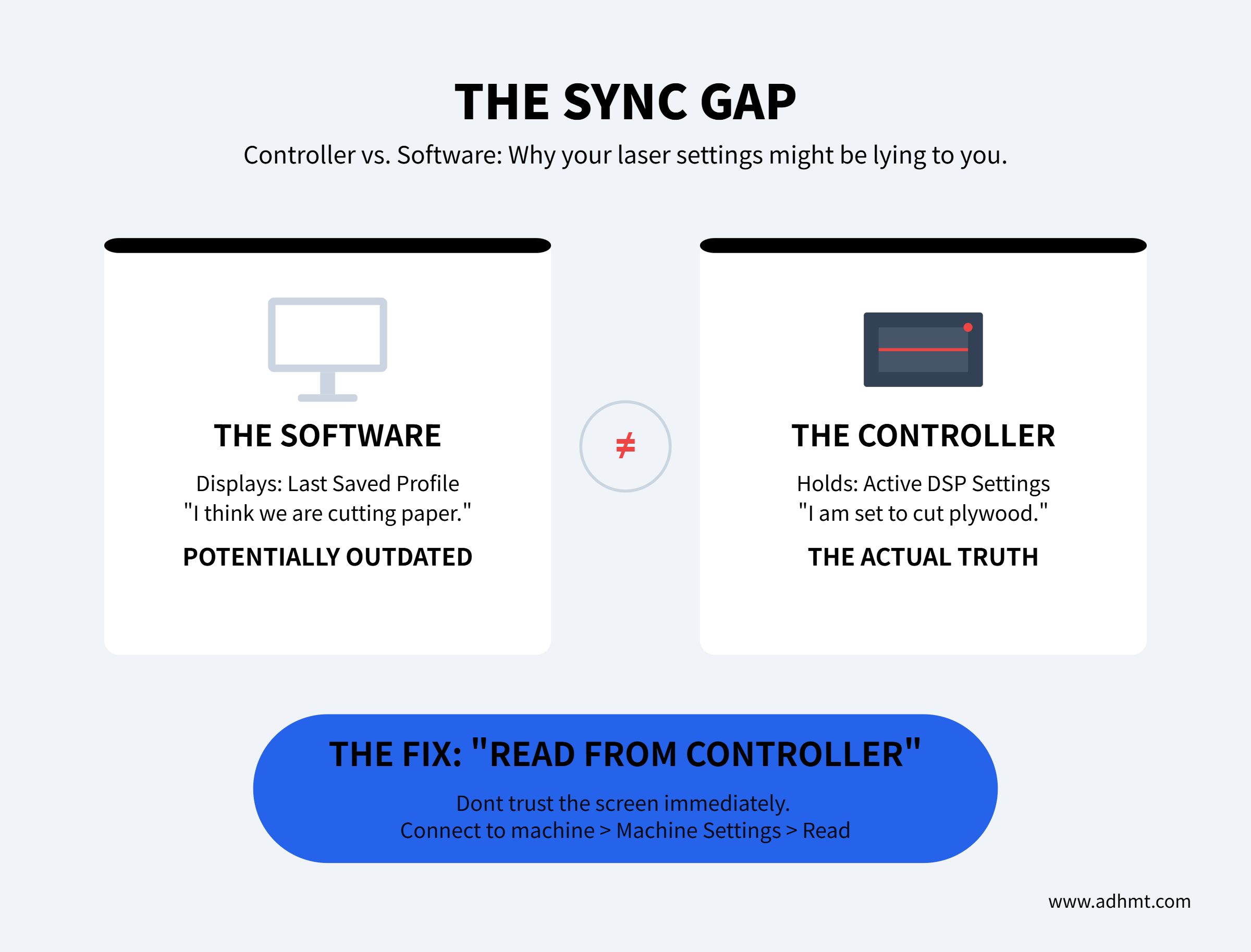
Always keep a "Known Good State" configuration file saved. After maintenance, if the machine behaves oddly, load this file and write it to the controller to eliminate software variables instantly.
When the Machine Is Fine but the Job Is Wrong: Software & Settings
You have verified the mirrors are aligned, the lens is clean, and the belts have the correct tension. Mechanically, the machine is perfect. Yet, the output is distorted, the dimensions are wrong, or the engraving looks like a blurry photograph.
When the hardware is sound but the result is flawed, the problem lies in the "brain" of the operation—the controller and the software instructions it receives. This is not a mechanical failure; it is a translation error. The machine is doing exactly what it is told to do; it is simply being told the wrong things.
Why Reinstalling the Driver Rarely Fixes Scaling or Offset Issues
When a design meant to be 100mm wide cuts at 98mm, or when an engraving has a "ghost" image slightly offset from the main design, the immediate instinct is to blame the computer driver. This is almost always a waste of time. The driver is merely a courier; it delivers data from your computer to the laser’s controller. If the courier delivers a letter written in the wrong language, firing the courier will not fix the translation.
The root cause of scaling issues is usually the Pulse Equivalent (in RDWorks) or Step Calibration ($100/$101 settings in LightBurn). The controller operates on steps, not millimeters. It needs to know exactly how many stepper motor pulses equal one millimeter of travel. If this value is off by even a fraction, the error compounds over distance. A 10mm test cut might look fine, but a 500mm job will be off by centimeters.
The Autopsy of a Scaling Error:
- You command a 50mm square cut.
- The controller calculates that it needs 5,000 pulses based on a stored setting of 100 steps/mm.
- The actual mechanical requirement is 101 steps/mm.
- The motor falls 50 pulses short per millimeter.
- The final cut measures 49.5mm.
- The Fix: Do not reinstall drivers. Cut a large rectangle (e.g., 100mm x 100mm), measure the actual output with calipers, and input the "Expected vs. Measured" values into the software’s calibration tool to update the pulse equivalent.
Similarly, "ghosting" or double-vision on raster engravings is rarely a driver glitch. It is a physics problem called Scanning Offset. As the laser head moves back and forth at high speeds (e.g., 500mm/s), there is a mechanical lag between when the laser fires and when the head is in position, due to belt stretch and inertia. If the software doesn't compensate for this lag, the left-to-right lines won't align with the right-to-left lines. You must run a scanning offset test (an engraved list of speeds) and enter the compensation values into the device settings.
DPI and Origin Errors That Ruin an Entire Batch
Nothing is more expensive than a software setting that ruins a full sheet of material. Two specific settings are responsible for the majority of "batch kills": DPI mismatch and Origin drift.
The DPI Trap: Operators often assume higher DPI (Dots Per Inch) equals higher quality. In laser processing, this is false. A laser beam has a physical width (kerf), usually around 0.08mm to 0.1mm. If you set the DPI to 600 or 1200 on a material that melts (like acrylic or wood), the laser pulses overlap heavily.
Instead of a crisp image, the heat accumulates, causing the material to boil or char. The result is a deep, dark blob where detail should be. For most CO2 lasers, 300 to 400 DPI is the maximum effective resolution before dot overlap destroys edge definition. If your image looks bloated or burnt, lower the DPI or use "Pass-through" mode in LightBurn to let the image's native resolution dictate the firing.
The Origin Drift: If you run a batch using "Current Position" rather than "Absolute Coordinates," you are inviting disaster.
- You set the origin manually at the corner of the material.
- The job finishes.
- You accidentally nudge an arrow key or the machine fails to return to the exact micro-step due to a loose belt tooth.
- You press "Start" for the next job.
- The machine treats the new random position as zero.
- The laser cuts the first part of the array directly through the edge of the material or into the honeycomb bed frame.
Always use Absolute Coordinates for batch work. This forces the machine to reference its internal home switches every time, ensuring that (0,0) on the screen is physically (0,0) on the bed, regardless of where the head was left hanging.
Material-Specific Betrayal: Why Acrylic Polishes One Day and Frosts the Next
You load a file that worked perfectly yesterday. The settings are identical: Speed 20mm/s, Power 80%. Yesterday, the edge came out flame-polished and clear. Today, the edge is white, frosty, and rough. You assume the tube is failing or the lens is dirty.
The culprit is almost certainly the material chemistry. Acrylic comes in two manufacturing types: Cast and Extruded. They look identical to the naked eye but react differently to thermal stress.
The Chemistry Autopsy:
- Cast Acrylic: Made by pouring liquid into a mold. It has long, tangled polymer chains. When hit by the laser, it doesn't melt easily; it turns to vapor. This results in a clean, polished edge and bright white engraving.
- Extruded Acrylic: Made by pushing pellets through rollers. It has short, directional polymer chains and high internal tension. When lasered, it melts into a gum rather than vaporizing. It tends to fuse back together behind the beam, leaving a burr or a frosty, stress-whitened edge.
If your settings haven't changed but your results have, you likely switched from Cast to Extruded stock without realizing it.
Furthermore, check your PPI (Pulses Per Inch) or frequency settings. A continuous wave (high PPI) creates a hot, polished edge on Cast acrylic but turns Extruded acrylic into a gummy mess. If you are forced to use Extruded material, you must lower the PPI to allow the material to cool slightly between pulses, preventing the "melt-back" effect. If the edge is frosty on Cast acrylic, the culprit is often humidity or air assist; moisture in the air or the material (acrylic is hygroscopic) can cause micro-cracking during the thermal shock of cutting.
When to Stop Fixing and Call It: Signs of Terminal Hardware Failure
Most troubleshooting guides operate on the optimistic assumption that every problem is solvable with a hex key and a cotton swab. They are wrong. There is a distinct line where calibration ends and necrosis begins. Crossing this line means you are no longer fixing a machine; you are performing CPR on a corpse.
If you are operating modern production equipment and repeatedly encountering terminal symptoms despite correct procedures, it may be time to review updated machine specifications or consult manufacturer documentation. Reviewing official brochures can help you benchmark whether your current system still meets your production and precision requirements.
The Tube Symptoms That Don’t Come Back (The "Pink Fade")
The most common casualty in laser cutting is the CO2 tube itself. Unlike a dull blade that can be sharpened, a laser tube is a sealed chemical environment. Once the chemistry fails, no amount of software tweaking will bring it back.
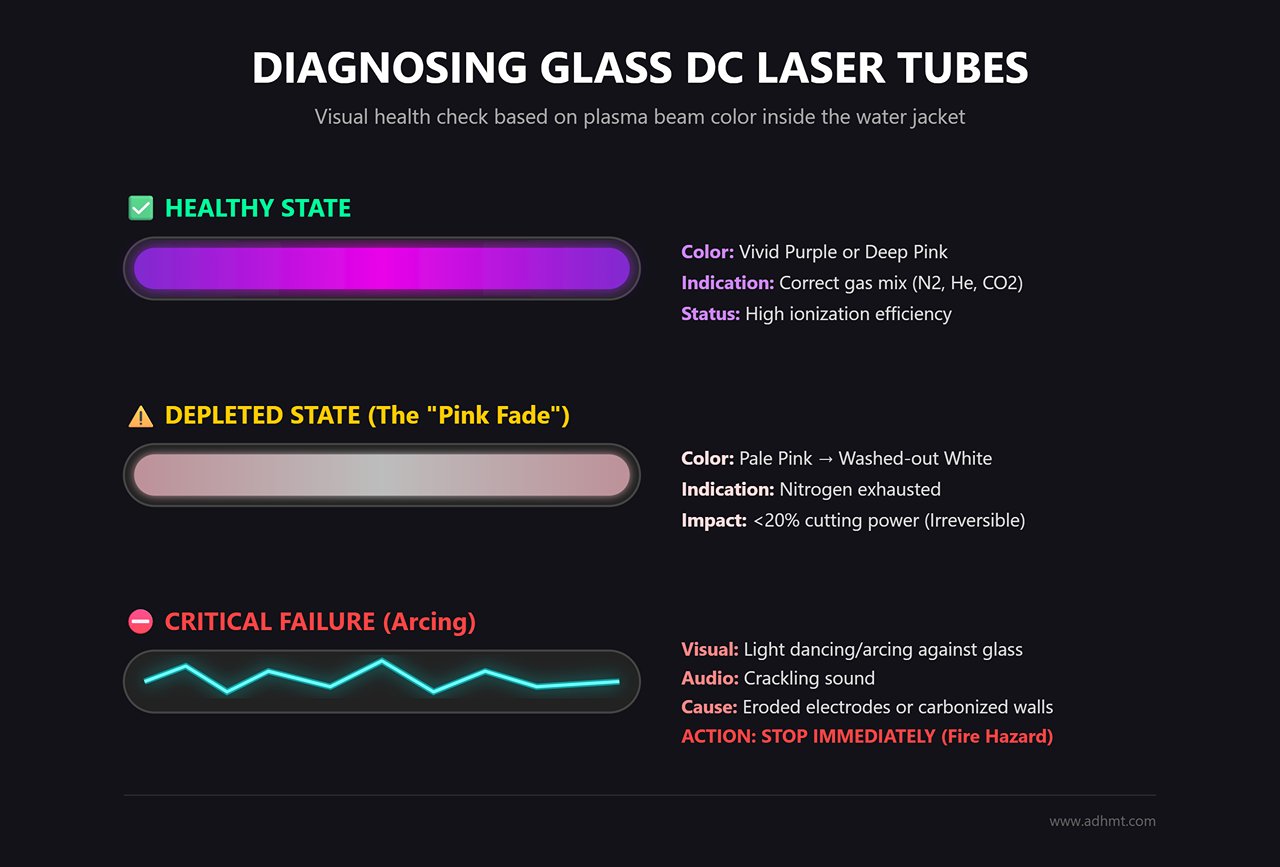
You can diagnose the health of a glass DC tube by looking at it—specifically, the color of the plasma beam inside the water jacket during operation.
- The Healthy Standard: A fresh tube containing the correct mix of Nitrogen, Helium, and CO2 glows a vivid purple or deep pink. This indicates high ionization efficiency.
- The "Pink Fade": As the gas mixture depletes or leaks over time, the discharge color shifts to a pale pink and eventually a washed-out white. If you see white light, the nitrogen is exhausted. The tube may still fire, but it will have less than 20% of its cutting power. This is irreversible.
- The Arcing Flicker: If the light inside the tube is dancing or arcing against the glass wall rather than flowing straight through the center, the internal electrodes are eroded or the inner wall is carbonized. This is often accompanied by a crackling sound. This is an immediate fire hazard and a "stop work" condition.
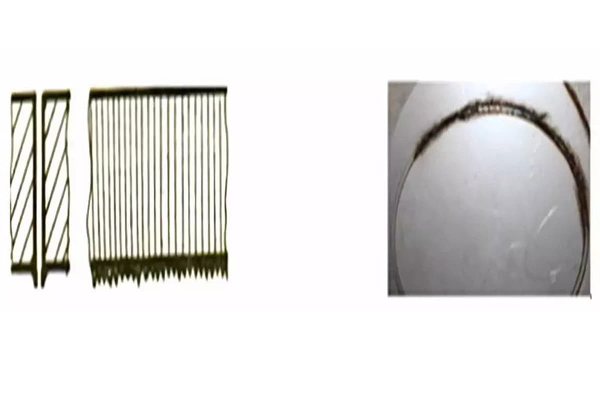
The TEM Mode Test Color is subjective; the burn pattern is not. Perform a "tape shot" directly out of the tube (before it hits the first mirror). A healthy tube produces a TEM00 mode: a single, dark, concentrated circle. If your tape shows a ring (donut shape) or scattered buckshot patterns, the resonant cavity of the tube has failed. This is a "multi-mode" failure. You cannot align a ring; you can only replace the generator.
Cost vs. Downtime: Knowing When Replacement Beats Repair
Operators often fall into the "Sunk Cost Fallacy," spending days trying to squeeze the last 500 hours out of a dying tube. This mathematical error ignores the cost of downtime.
For standard glass tubes (40W–150W), the decision should be driven by a simple ROI threshold: If the cost of downtime exceeds the price of the component, replace immediately.
Consider the math for a standard production floor:
- Glass Tube Cost: $300 (approximate for 80W)
- Shop Rate: $100/hour
- The Threshold: If you spend more than 3 hours troubleshooting a $300 tube, you have lost money.
If you are running a high-end RF metal tube (Synrad, Coherent), the math changes. These units cost $2,000 to $10,000 and are designed to be refilled. However, the turnaround time for an RF refill is often 2–4 weeks.
- The Rule of RF: If you do not have a backup tube on the shelf, the cost of a 3-week shutdown dwarfs the cost of a new unit. Smart shops swap in a spare and send the dead core out for refurbishment, treating it as a rotational asset rather than a repair job.
The "Zombie Tube" Hidden CostA tube running at 70% efficiency is a silent profit killer. To compensate for power loss, you must slow your cutting speed. If a job that usually takes 20 minutes now takes 30, you have increased your labor and overhead costs by 50% per part. A $500 tube pays for itself in less than a week simply by restoring your feed rates to normal levels.
What to Tell a Technician So You Don’t Pay for Guesswork
If you decide to call in a professional, remember that technicians bill by the hour. If you tell them "it’s not cutting right," they will spend the first three hours ($450+) performing the diagnostics you could have done yourself.
To minimize the bill, hand them a "Death Certificate" comprising data, not feelings. Before you call, gather these four specific data points:
- The Amperage Reading (mA): Run the machine at 100% power and record the milliamp reading on the power supply’s ammeter. If a tube rated for 28mA is maxing out at 18mA despite the software calling for 100%, the power supply or tube impedance has failed.
- The Visual Evidence: Take a 10-second video of the tube while firing. Capture the color of the plasma and the condition of the anode (the high-voltage end).
- The Thermal History: Report the water temperature. "It’s running at 20°C" is useful; "It overheated to 45°C last Tuesday" is diagnostic gold, indicating a likely seal rupture.
- The Life Counter: Check the controller for total laser-on hours. A glass tube with 4,000 hours is simply at the end of its life; a technician cannot "fix" old age.
By providing this dossier—"I have a white plasma discharge, max current is capped at 15mA, and the tube has 3,500 hours"—the technician can skip the diagnostic visit and arrive with the correct replacement part in hand, turning a two-visit repair into a one-visit swap.
The "First Job Back" Protocol: Ensuring the Fix Sticks
You have identified the symptom, dismantled the components, and applied the fix. The laser fires, the head moves, and the hum of the chiller sounds normal. The temptation to immediately load a client’s expensive walnut slab or acrylic sheet is overwhelming.
Resist that urge.
A machine that turns on is not necessarily a machine that is fixed. A repair often introduces new variables—belt tension changes, mirror misalignment, or software setting drifts. The "First Job Back" Protocol is a mandatory interrogation of your machine. It transforms hope into data, ensuring that your first paid cut doesn't end in the scrap bin.
The 1-Inch Square Test: Verifying Dimensions and Squareness
Before you attempt complex geometries, you must verify the fundamental truth of the machine’s movement. The most efficient way to do this is the "1-Inch Square Test." This isn't just about checking if the laser cuts; it is a forensic analysis of your motion control system.
The Action: Open your control software (LightBurn or RDWorks) and draw a 25.4mm x 25.4mm (1 inch) square. Set the speed to 20mm/s and power to 50% (adjust for material, typically 3mm acrylic or MDF). Cut this square near the machine origin.
The Diagnosis: Once the part cools, use digital calipers to measure it. Do not use a ruler; you need 0.1mm precision.
- Check Dimensions (X and Y): The sides should measure exactly 25.4mm ±0.1mm.
- If the side is short or long: Your pulse calibration (steps per mm) is incorrect. In LightBurn, go to Machine Settings > Calibrate Axis to adjust the step length based on your measured result versus the requested size.
- If the corners are rounded: You have backlash. This usually indicates a loose belt (aim for 110Hz tension) or a loose pinion grub screw on the stepper motor.
- Check Squareness (The Diagonals): Measure the distance from top-left to bottom-right, and top-right to bottom-left.
- The Mathematical Truth: For a perfect 25.4mm square, the diagonal must be approximately 35.92mm. More importantly, both diagonals must be identical.
- If diagonals differ by >0.2mm: Your gantry is not square. The X-axis is not perpendicular to the Y-axis. You must physically adjust the Y-axis belts or use the "squaring" function in your software to compensate, though physical adjustment is always superior.
If this square fails, the machine is not ready. Adjust and repeat until the physical output matches the digital input.
Stress-Testing Stability Before Accepting a Paid Job
A 1-inch square proves your geometry is correct cold. It does not prove your machine can handle the heat and vibration of a 4-hour engraving job. Repairs often fail under load—a belt slips only when the carriage moves at high speed, or a stepper driver overheats and loses steps after 30 minutes.
**The "Burn-In" Protocol:**Simulate a paid job without risking paid inventory.
The Full-Bed Frame: Cut a large rectangle that traces the perimeter of your bed (e.g., 500x500mm on a mid-sized machine) at high speed (100% travel speed, low power).
- What to watch for: Listen for grinding or stuttering at the far ends of the rails. If the gantry binds at the rear of the machine but moves freely at the front, your frame is racked (twisted).
The Endurance Run: Run a complex raster engraving job on scrap cardboard for at least 30 minutes.
- The Check: After the job finishes, immediately command the laser to return to the "Pulse" origin point and fire a test dot. If the dot does not land exactly on top of the starting origin, you have "step loss." This implies a mechanical slip or an electrical issue (overheating drivers or electrical noise).
The Thermal Drift: If you replaced a tube or power supply, monitor the milliammeter (mA) and water temperature.
- The Limit: If the amperage drops by more than 10% during a constant cut, or if water temperature spikes above 22°C (for glass tubes), the cooling system is insufficient for the new components.
Do not sign off on the repair until the machine completes a full cycle without drifting, skipping, or fading.
The Simple Maintenance Log That Saves Future-You Hours of Guessing
The difference between a frantic operator and a calm technician is documentation. When a problem recurs six months from now, you will not remember that you swapped the X-axis driver or that you changed the step calibration to 0.051mm/pulse.
Create a "Machine Fingerprint" log. This doesn't need to be complex; a clipboard zip-tied to the chiller or a simple Excel sheet works.
The Essential Entries:
- Date & Symptom: e.g., "12/29 - Jagged edges on circles."
- The Fix: e.g., "Tightened X-belt to 110Hz; Cleaned Mirror 2."
- The Verification: "1-inch square: 25.41mm / Diagonals match."
- The Baseline Parameters: Record the working amperage (mA) for a specific cut (e.g., "10mm Acrylic cuts clean at 28mA @ 8mm/s").
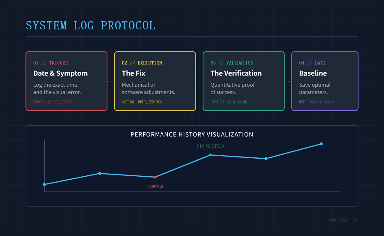
Why This Matters: Next time the machine cuts poorly, you look at the log. If the amperage for that same 10mm acrylic cut is now reading 22mA instead of 28mA, you immediately know your tube is aging or your power supply is failing. You skip the hours of checking focus, alignment, and belts because your data points directly to the power source.
The "First Job Back" isn't the one you ship to the client. It's the one you run to prove that you can ship to the client tomorrow, next week, and next month without hesitation.
If you encounter recurring issues, require application-specific guidance, or are considering upgrading to a more efficient cutting platform, don’t hesitate to contact us for technical support or machine consultation tailored to your production needs.


