I. What Is A Bending Machine
A bending machine is suitable for bending sheet metal and shaping workpieces in sheet metal fabrication. Bending machines are used for a variety of purposes, such as bending tubes, folding plates, and rolling plates.
There are many types and functions of bending machines, which can either serve as a press or a bending machine. Today, I will show you the basic guide to bending machines.
Some bending machines can process sheet metal directly without the need for clamping tools, while others require clamping tools to assist with bending. The metal sheet is secured by the clamping device and remains in place throughout the entire processing process.
The bending machines can also use the bending tool to shape the metal plate and create the desired profile. The body and tools of the bending machine must be made of special materials to ensure that they can withstand the pressure applied during processing without being damaged.
The following is a comprehensive guide to metal bending machines, which covers different types of bending machines and provides detailed operating steps and precautions, specific functions and applications of pipe bending machines, metal sheet bending machines, plate rolling machines, and press brakes.
II. Types of Bending Machine
There are several types of bending machines, including pipe bending machines, sheet metal bending machines, sheet folding machines, hydraulic bending machines, mechanical bending machines, electric servo bending machines, electric pipe bending machines, and cutting and punching machines, among others.

1. Pipe bending machine
(1) What Is A Pipe Bender
Pipe bender is a machine that is used for bending metal pipes and profiles into various shapes. The profiles are usually square or rectangular in shape and are made of thick metal. Bending is a stretching process that generates friction between the pipes and the bending tools.
To extend the life of the tools and the pipe bender, drawing oil can be used to reduce the resistance between the pipe and the tools. Pipe bending and manufacturing equipment are utilized for performing various operations such as bending, swaging, flaring, and crimping.
The pipe bender can bend various metal materials such as stainless steel, iron, copper, aluminum, titanium, and carbon steel. These materials have a high degree of ductility and small elastic deformation, which makes them suitable for supporting the structure of the bent section.
The pipes processed by the pipe bender have a smooth and uniform curve, with no external collapses or internal folds. The pipe is a hollow container that is widely used for transporting gas, solids, and fluids in various industrial, medical, and other equipment.
The pipe bender is mainly used for laying pipes in construction projects, such as in buildings, highways, railways, bridges, and more.
(2) Structure of Pipe Bending Tools
The pipe bending machine consists of the clamp die, bend die, pressure die, wiper die, and mandrel. The dies of the pipe bender are typically made of hardened steel to withstand the bending process and prevent damage.
However, tools like wiper dies are made of softer materials such as aluminum or brass to prevent damage to the pipes being bent.
Bend die
The bend dies, also known as the radius die, is a crucial part of the rotary drawing process. It holds the pipe in place and bends it during the drawing process. The shape of the bend die determines the inner radius of the bent pipe.
Clamp Die
The clamp die is used in conjunction with the bend die to hold the pipe in place and prevent it from slipping during the bending process.
Wiper die
The wiper die smoothens the surface of the bent pipe and prevents the inner radius from collapsing and the outer surface from being damaged. Made of softer materials such as aluminum or brass, the wiper die helps prevent damage to the pipes.
Pressure die
The pressure die is used to apply pressure to the pipe during the bending process, ensuring a consistent and accurate curved profile.
Mandrel
Mandrels are used to support the bending of small-radius pipes, thin tubes, and hard materials. They work with the wiper die to prevent the pipes from wrinkling on the inside and collapsing on the outside during the bending process.
(3) How Does A Pipe Bending Machine Work
A pipe-bending machine works by applying pressure to bend pipes. The source of this pressure can be hydraulic, electric servo, pneumatic, or manual. The pipe is first clamped in place by the clamping block and forming tools and adjusted to the shape of the die.
Then, as one end of the pipe rotates and rolls around the die, it is fixed in place. There are also other methods of processing pipes through rollers to form profiles. When bending pipes, a mandrel is often inserted inside to prevent the inside of the pipe from collapsing and wrinkling.
The scraping die of the pipe bender helps maintain tension on the pipe and prevent damage when force is applied. The wiper dies, typically made of aluminum or brass, help prevent scratches on the raw material.
There are several different bending methods of bending pipes with a pipe bending machine, including press bending, rotary draw bending, compression bending, roll bending, mandrel tube bending, wiper die bending, heat induction bending, sand packing and hot slab forming, and ram bending.
(4) Operating Steps
- Preparation: Ensure the work area is clean and free of obstacles. Check that all parts of the bending machine, especially the bending dies and clamps, are in good condition.
- Install the Die: Select the appropriate die based on the required bending angle and pipe diameter. Install the die on the machine's worktable and ensure it is securely fixed.
- Secure the Workpiece: Place the pipe to be bent on the die. Use clamps to secure the pipe, ensuring it will not move during the bending process.
- Adjust the Angle: Adjust the machine's angle settings according to the required bending angle. Start the machine and gradually apply pressure until the desired bending angle is achieved.
- Check and Adjust: Release the pressure and remove the pipe to check if the bending angle meets the requirements. If adjustments are needed, make fine adjustments and repeat the above steps.
(5) Precautions
Keep hands and other body parts away from the bending area during operation to avoid injury. Regularly inspect and maintain the bending machine to ensure it is in good working condition. Use appropriate protective gear, such as gloves and safety glasses.
2. Metal Sheet Bending Machine
A sheet metal bending machine is a machine that bends sheet metal, suitable for shaping sheet metal into specific profiles. The metal sheet is positioned on the lower die of the workbench and then pressed by punches to complete the bending process.
The movement of the slider, which is driven by the power system, results in the downward movement of the punch. This type of machine can bend metal sheets or pipes to any angle. If the machine is specifically designed for bending pipes, it is referred to as a pipe-bending machine.
The sheet metal bending machines are essential tools to achieve complex bending requirements, which are suitable for processing larger workpieces that other machines cannot handle. The workpiece is securely held in place by the clamping shaft, driven by the power system.
After the workpiece is fixed, the folding arm of the swing beam swings in an arc, bending the flange to the desired angle.
(1) Operating Steps
- Preparation: Ensure the work area is clean and free of obstacles. Check that all parts of the bending machine, especially the bending dies and clamps, are in good condition.
- Install the Die: Select the appropriate die based on the required bending angle and sheet thickness. Install the die on the machine's worktable and ensure it is securely fixed.
- Secure the Workpiece: Place the metal sheet to be bent on the die. Use clamps to secure the sheet, ensuring it will not move during the bending process.
- Adjust the Angle: Adjust the machine's angle settings according to the required bending angle. Start the machine and gradually apply pressure until the desired bending angle is achieved.
- Check and Adjust: Release the pressure and remove the sheet to check if the bending angle meets the requirements. If adjustments are needed, make fine adjustments and repeat the above steps.
(2) Precautions
- Keep hands and other body parts away from the bending area during operation to avoid injury.
- Regularly inspect and maintain the bending machine to ensure it is in good working condition.
- Use appropriate protective gear, such as gloves and safety glasses.
3. Plate Rolling Machine
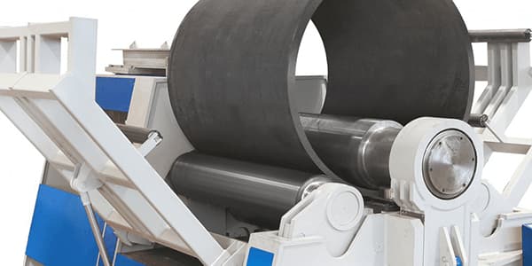
A pyramid-type mechanical plate bending machine is utilized for bending and forming metal plates. The bottom roller is powered by a motor and gear and can rotate. The upper roller's required bending radius can be adjusted manually up and down.
The steel plate bending machine features a double-sided pre-clamping device, with a unique structure that enables the two bottom rollers to pre-clamp the workpiece. The upper roller is fixed and pre-clamped by the two lower rollers through hydraulic cylinders.
(1) Operating Steps
- Preparation: Ensure the work area is clean and free of obstacles. Check that all parts of the roll bending machine, especially the rollers and clamps, are in good condition.
- Install the Rollers: Select the appropriate rollers based on the required bending radius and plate thickness. Install the rollers on the machine's worktable and ensure they are securely fixed.
- Secure the Workpiece: Place the plate to be bent on the rollers. Use clamps to secure the plate, ensuring it will not move during the bending process.
- Adjust the Parameters: Set the machine's parameters, such as pressure and speed, according to the required bending radius and plate characteristics.
- Start the Rolling Machine: Start the machine and gradually apply pressure to perform the bending operation. Monitor the bending process to ensure the plate bends as expected.
- Check and Adjust: Release the pressure and remove the plate to check if the bending radius meets the requirements. If adjustments are needed, make fine adjustments and repeat the above steps.
(2) Precautions
- Ensure the rolling machine is free of leaks and regularly inspect and maintain the rollers.
- Keep hands and other body parts away from the bending area during operation.
- Use appropriate protective gear, such as gloves and safety glasses.
4. Press Brake Machine
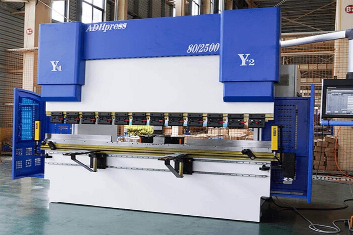
Press brake is a type of bending machine that is used for metal forming andbending a sheet metal plate. There are various types of press brakes that are powered by different systems. The press brake has at least three shafts on the rear gauge, which allows for control over the accuracy, speed, and stroke of the machine. It is equipped with a CNC controller for precise bending. Thus, the machine can make the metal to the desired angle, which is easy to operate, and can process workpieces in bulk.
(1) Operating Steps
- Preparation: Ensure the work area is clean and free of obstacles. Check that all parts of the press brake, especially the dies and clamps, are in good condition.
- Install the Die: Select the appropriate die based on the required bending angle and sheet thickness. Install the die on the machine's worktable and ensure it is securely fixed.
- Secure the Workpiece: Place the metal sheet to be bent on the die. Use clamps to secure the sheet, ensuring it will not move during the bending process.
- Set the Parameters: Set the machine's parameters, such as pressure and speed, according to the required bending angle and sheet characteristics.
- Start the Press Brake: Start the machine and gradually apply pressure to perform the bending operation. Monitor the bending process to ensure the sheet bends as expected.
- Check and Adjust: Release the pressure and remove the sheet to check if the bending angle meets the requirements. If adjustments are needed, make fine adjustments and repeat the above steps.
(2) Precautions
- Ensure the press brake is free of leaks and regularly inspect and maintain the dies.
- Keep hands and other body parts away from the bending area during operation.
- Use appropriate protective gear, such as gloves and safety glasses.
5. Sheet Folding Machine
Sheet folding machines bend sheet metal by sandwiching it between two or more clamps and then bending it to the desired angle. These machines are commonly used to produce parts with straight sides, such as boxes and drawers. Sheet folding machines are essential in the production of various metal enclosures and structural components.
6. Cutting and Punching Machine
Cutting and punching machines, while primarily used for cutting and punching operations, can also perform bending tasks. These versatile machines can handle multiple metal processing tasks, making them valuable in various manufacturing environments. They are commonly used in the production of metal brackets, connectors, and structural supports.
7. Rotary Stretch Bender
Rotary stretch benders use a mandrel and a stationary die to bend metal tubing or pipe, preventing it from collapsing or deforming during the process. These machines are particularly useful for creating complex bends in metal tubing used in automotive and aerospace applications.
8. Incremental Benders
Incremental benders achieve complex shapes and angles by using a series of small incremental bends. These machines are often used in the production of complex sheet metal components, such as those required in the aircraft and automotive industries. Incremental benders are ideal for applications that demand high precision and intricate geometries.
Comparison Between Machine Types
| Feature | Manual | Hydraulic | CNC | Electric |
| Cost | Low | Medium | High | Medium |
| Ease of Use | Moderate | Moderate | Easy | Easy |
| Precision | Moderate | High | Very High | High |
| Automation Level | None | Semi-Automated | Fully Automated | Semi-Automated |

Ⅲ. Key Parameters in Bending
1. Basic Parameters: Bend Radius and Bend Angle
(1) Bend Radius
In technical contexts, this typically refers to the centerline radius — the distance from the center of curvature to the tube’s centerline. It is the defining measure of how tight the bend is. A smaller radius results in a sharper bend, but also imposes greater challenges on both material and manufacturing processes.
(2) Bend Angle
This is the degree to which the tube deviates from its original straight position. For example, a 90° bend means the tube changes direction by 90 degrees. While 45° and 90° bends are most common, virtually any angle can be produced to meet specific application needs.
2. Critical Variables: Material Springback and Bend Allowance
(1) Material Springback
Springback is one of the most common and critical factors in tube bending. Once the bending force is released, internal elastic stresses cause the material to partially revert toward its original shape, making the final bend angle smaller than intended.
The root cause lies in the uneven stress distribution during bending. The outer wall undergoes tension while the inner wall experiences compression, altering molecular density. When the external force is lifted, the material seeks equilibrium, resulting in springback.
The most direct way to compensate is overbending — bending slightly beyond the target angle. For instance, if testing shows a particular batch springs back by 3° after a 90° bend, you would bend it to 93° to achieve an accurate 90° after springback. Because the amount of springback can vary with batch, thickness, and even ambient temperature, performing a test bend before each new production run is essential.
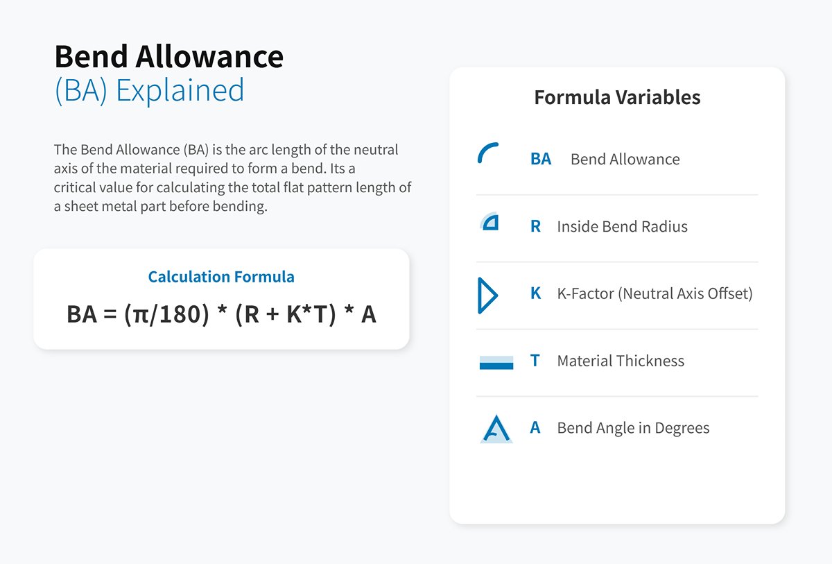
(2) Bend Allowance
Bend allowance doesn’t mean extra material; rather, it is the arc length along the neutral axis required to form a bend when calculating cut lengths. In other words, it’s the portion of material “used up” in the bend. Accurate calculation of bend allowance is vital for achieving the designed final length of the part. A common formula is:
BA = (π / 180) * (R + K·T) * A
Where R is the inside bend radius, K is the K-factor, T is material thickness, and A is the bend angle. For those looking for a practical tool to simplify these calculations, a comprehensive Bend Allowance Chart: Complete Guide can be an invaluable resource.
3. K-Factor and the Neutral Axis
(1) Neutral Axis
During bending, there is a theoretical plane within the cross-section that is neither in tension nor compression — its length remains unchanged before and after bending. This is called the neutral axis.
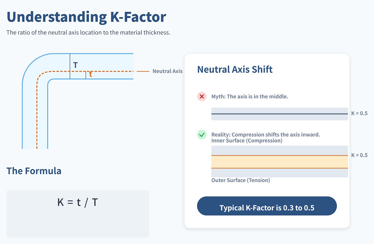
(2) K-Factor
A core concept in mastering bend calculations, the K-factor is the ratio that precisely locates the neutral axis within the material thickness. It is defined as:
K = t / T
Where T is total material thickness and t is the distance from the neutral axis to the inner surface.
A common misconception is that the neutral axis lies exactly halfway through the thickness (K = 0.5). In reality, because the inside of the bend is under compression, the neutral axis shifts toward the inside, and the K-factor typically ranges from 0.3 to 0.5. This offset depends on material type, thickness, bend radius, and the bending method used (e.g., air bending, bottoming, or coining).
There is no universal K-factor. Precision manufacturing requires building a dedicated K-factor database for each material and process combination. The accuracy of the K-factor directly determines the success of bend allowance calculations — it is the mathematical foundation for high-precision bending.
4. Fundamental Differences Between Tube Bending, Sheet Bending, and Rolling
Although all three are metal forming processes, their objectives, methods, and application scenarios differ fundamentally.
| Feature | Tube Bending | Sheet Bending | Rolling |
|---|---|---|---|
| Workpiece | Hollow tubing and profiles (round, square, etc.) | Flat metal sheet | Flat metal sheet or profile |
| Forming Characteristics | Changes the tube’s path along a continuous curve to create a smooth arc; often requires a mandrel to prevent cross-section deformation | Creates a sharp angle along a straight line, forming V, U, or Z shapes | Gradually bends sheet or profile into large-radius arcs, or even closed cylinders or cones |
| Core Equipment | Tube bender (with specialized dies and mandrels) | Press brake using an upper punch and lower V-die | Plate rolling machine, typically with a three-roll or four-roll system |
| Main Applications | Piping systems (fluid conveyance), structural frames (automotive, furniture), exhaust systems, handrails, etc. | Enclosures, chassis, brackets, boxes, and components requiring crisp edges | Storage tanks, pressure vessels, large pipes, wind towers, curved building structures, etc. |
| Key Difference | The priority is maintaining the integrity of the hollow cross-section; focus on “guiding” and “supporting” | Focus is on producing precise straight-line bends; emphasis on “pressing” | Focus is on producing large-radius continuous curves; the only method that easily creates multiple different radii on the same workpiece; emphasis on “progressive rolling” |
To learn more about the specific models and technical capabilities available for these applications, feel free to browse our Brochures.
5. Operating Steps
(1)Preparation
Ensure the workspace is clean and free of obstructions. Inspect all components of the bending machine, especially the dies and clamps, for proper condition.
(2)Install Dies
Select the die suitable for the required bend angle and tube diameter. Mount the die onto the machine’s worktable and secure it firmly.
(3)Secure the Workpiece
Position the tube onto the die. Use clamps to hold it in place, ensuring it will not shift during bending.
(4)Adjust Angle
Set the machine to the desired bend angle. Start the machine and gradually apply pressure until the target angle is reached.
(5)Check and Adjust
Release pressure and remove the tube. Measure the bend angle to ensure it meets requirements. If adjustments are needed, fine-tune and repeat the process.
6. Safety Precautions
Keep hands and other body parts clear of the bending area during operation to prevent injury. Regularly inspect and maintain the bending machine to keep it in optimal working condition. Always wear proper protective gear, such as gloves and safety glasses.
7. Core Calculations
(1) Calculating the Developed Length
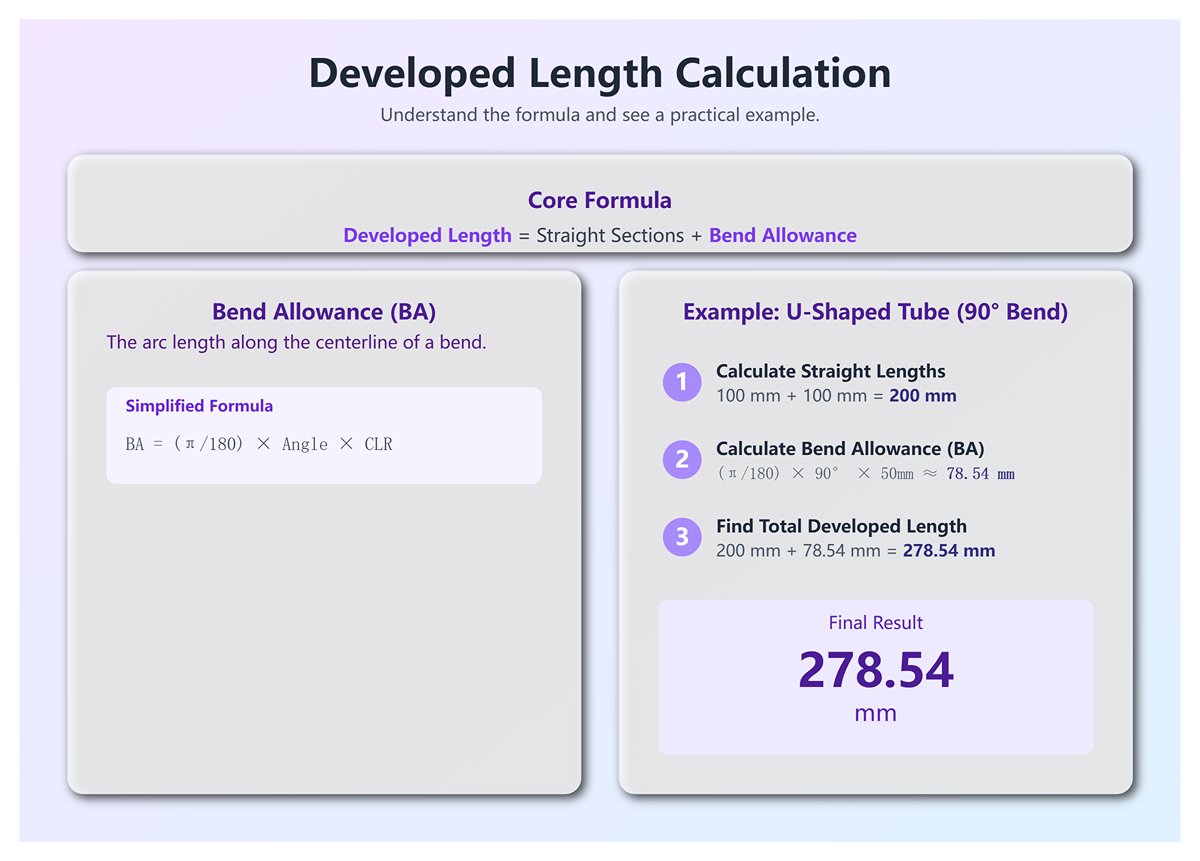
How long should your straight tube be to achieve the final part? The answer lies in calculating the developed length, using this core formula:
Developed Length = Sum of all straight sections + Sum of arc lengths for all bends (i.e., bend allowances).
Example: You need a U-shaped tube with two straight ends of 100 mm each, joined by a 90° bend with a centerline radius (CLR) of 50 mm.
1)Length of straight sections: 100 mm + 100 mm = 200 mm.
2)Arc length of bend (bend allowance): To be calculated first.
3)Final cut length: 200 mm + the calculated bend allowance.
(2) Bend Allowance and Springback Compensation Calculations
Bend Allowance (BA) Calculation
Bend allowance represents the actual length along the centerline of the bend. The simplified formula is:
BA = (π / 180) × Bend Angle × Centerline Radius (CLR).
High-precision formula (accounting for K-factor):
BA = (π / 180) × Bend Angle × (CLR + K-factor × Wall Thickness).
For most pipe bending tasks, a simplified formula is more than sufficient. The high-precision formula is used more often in sheet metal bending, where the K-factor has a greater influence.
Continuing with the previous example:
BA = (3.14159 / 180) × 90° × 50 mm ≈ 78.54 mm
Therefore, your developed length (cut length) should be 200 mm + 78.54 mm = 278.54 mm.
(3) Springback Compensation Calculation
Theoretical springback calculations are highly complex. For beginners and most shop-floor environments, the most reliable and straightforward approach is trial bending followed by measurement.
1)Sampling: From the same batch of tubing you plan to use, take a scrap piece to serve as a test sample.
2)Initial Bend: Set your target angle on the bender, for example 90°, and perform the bend without entering any springback compensation.
3)Measurement: Once bending is complete, remove the workpiece and measure its natural, relaxed angle with a precision protractor. Suppose you record an actual angle of 87°.
4)Calculate the Compensation Value: Springback amount = target angle – actual angle = 90° – 87° = 3°.
5)Apply the Compensation: Enter this 3° value into the bender’s control system as the springback compensation. Now, when you set a 90° bend, the machine will automatically overbend to 93° so that after springback you achieve a perfect 90° angle.
IV. Advanced Techniques
1. Four Advanced Compensation Methods
Simply adding a fixed offset to your target angle is a beginner’s approach. Master craftsmen use more scientific, dynamic techniques to tame springback—the most significant variable in the bending process.
(1) Data-Driven Scientific Overbending
This method epitomizes turning experience into science. Instead of doing repeated “test–measure–adjust” cycles for every angle, you can build a simple springback model for the material to make predictive adjustments.
1)Two-Point Calibration: For material from the same batch, measure the actual springback for a small angle (e.g., 30°) and a large angle (e.g., 120°).
2)Generate the Springback Curve: Input these two data points into a modern CNC bender’s control system or specialized bending software. The system will use them to generate an automatic springback compensation curve.
3)Accurate Prediction: Using this curve, the machine can now automatically calculate and apply
a precise compensation value for any target bend between 0° and 180°, enabling “first-pass” accuracy and dramatically improving efficiency and first-piece yield for complex multi-bend parts.

(2) Process Tension Control
The root cause of springback lies in the stress differential across the material during bending (tension on the outside, compression on the inside). By actively influencing this stress distribution during the bend, you can significantly reduce springback.
1)Pressure-Die Assist: A key feature of high-end CNC benders. During bending, the pressure die not only supports the tube but also actively pushes forward. This forward force significantly reduces compressive stress on the inner side, shifting the wall’s stress balance more toward tension, thereby minimizing springback.
2)Post-Stretching: In some advanced sheet forming processes, the material is “locked” and stretched at the end of forming to set the shape and relieve internal stress. While not identical in tube bending, pressure-die assist applies the same physical principle.
(3) Stress-Relief Method
For certain high-strength, high-springback materials (such as titanium alloys or specific high-strength steels), room-temperature bending may be insufficient or may induce excessive internal stress.
Hot Bending: Apply localized, controlled heating to the bend area to raise it to a temperature below the recrystallization point where ductility is significantly improved. At this stage, the material’s yield strength is greatly reduced, bending forces are lower, and springback is minimized. This is a specialized but effective method, often used for thick-walled tubes or large-radius bends on hard-to-form materials.
(4) Tooling-Design Compensation
In sheet metal bending, a common compensation technique involves designing the punch and die angles to be sharper than 90°, physically overbending to offset springback. While the principle differs in tube bending, optimizing tooling design can achieve similar effects.
For example, using a specially shaped mandrel that applies targeted forming forces to the tube’s inner wall during bending can help influence the final springback angle and cross-sectional shape.
(5) Case Analysis: Springback Differences & Solutions for High-Strength Steel vs. Aluminum Alloys
| Property / Material | High-Strength Steel (AHSS) | Aluminum Alloy | Master’s Strategy |
|---|---|---|---|
| Elastic Modulus | High (~210 GPa) | Low (~70 GPa, about 1/3 of steel) | For aluminum alloys, preset a much larger springback compensation; overbend angles may need to be more than three times those for steel |
| Yield Strength | Extremely high, pronounced work-hardening | Medium to high | AHSS gains strength rapidly during bending, causing large and process-sensitive springback; requires highly accurate compensation models and very stable equipment |
| Springback Behavior | Significant springback | Extreme springback | Aluminum has a narrow bending window, easily resulting in “overbending” or underbending; scientific calibration is essential |
| Main Challenge | Large, unstable springback, sensitive to batch and process variables | Very large absolute springback, hard to get right in one shot | For AHSS: focus on controlling variables and process monitoring to ensure consistency; for aluminum: focus on precise calibration and understanding springback patterns |
2. The Precision Challenge: Achieving ±0.5° Tolerance
A ±0.5° tolerance is considered precise in many applications, but achieving it consistently requires a systematic optimization approach.
You may have seen that in press brake work, adjusting the “V-opening” affects bending results. In rotary draw tube bending, the bend radius is determined directly by the bend die’s radius (CLR). The key to optimization lies in precise matching between tooling and material, and in systematically eliminating sources of error.
(1) Optimizing Tooling-to-Material Fit
The first step to high-precision bending is having a set of ideal, zero-clearance tooling. Any unnecessary gap between the tube, bend die, clamp die, pressure die, or mandrel introduces uncontrolled variables into the bend. For precision work, customized, high-accuracy tooling is essential.
(2) Eliminating Cumulative Error in Multi-Bend Production
When producing a complex tube with 10 bends, even a tiny error of 0.2° per bend can be magnified in 3D space. This can lead to end-position deviations of several millimeters—or even centimeters—by the final bend.
Total Error = C-axis error (angle) + Y-axis error (length) + B-axis error (rotation). These errors add together and propagate through the bending sequence.
Solution: Closed-Loop Measurement and Correction

1)First-Part Trial: Use the calculated theoretical Y-B-C data to produce the first tube.
2)3D Scanning: Place the tube on a coordinate measuring arm (CMM arm) or a non-contact optical inspection system for scanning.
3)Data Comparison: The measurement software precisely compares the scanned 3D data to the original CAD model and generates a detailed deviation report.
4)Generate Correction File: This is the critical step! The software automatically calculates the precise fine-tuning needed to align the actual results perfectly with the design specifications. For example, the report might recommend: “Increase the angle of Bend 3 (C3) by 0.18°, shorten the straight length before Bend 4 (Y4) by 0.3 mm, and reduce the rotation before Bend 5 (B5) by 0.25°.”
5)Apply Correction: Import the correction file directly into the CNC tube bending machine, which will automatically use the revised data in production.
Through this "measure–compare–correct" closed-loop process, cumulative errors can be eliminated at the root, enabling consistently high-precision fabrication of even the most complex tubing. This method is the industry-standard workflow in modern aerospace and automotive piping manufacturing.
3. Introduction to Complex Geometry Machining
(1) Offsets
An offset consists of two bends with equal angles but opposite directions in the same plane, allowing the tube to shift laterally to bypass obstacles. The key lies in ensuring both bends are in exactly the same plane with identical angles, and that the straight segment between them is precisely measured. On a CNC machine, this is achieved through accurate control of the Y-axis (straight feed) and the C-axis (bend angle).
In sheet metal work, “flattening” refers to folding an edge completely over. In tubing, the equivalent is end forming, where the tube’s end is reshaped to allow connections or perform specific functions. This usually requires dedicated machinery (tube end forming machines), but in high-end bending units, it can be integrated. Common types include:
| Process Name | English Term | Definition | Function / Application | Features |
|---|---|---|---|---|
| Flared | Flaring | Expanding the tube end into a flared, trumpet-like shape | Works with a fitting to create a seal via a tapered or sealing surface | Increases sealing area; commonly used in refrigeration and hydraulic lines |
| Tapered | Swaging / Reducing | Reducing the tube end diameter | Allows insertion into another tube or connection to smaller-diameter fittings | Enables joining tubes of different diameters; often used in copper and aluminum tube processing |
| Flanged | Flanging | Folding the tube end outward to form a flange perpendicular to the tube axis | Enables detachable, sealed joints with bolts, gaskets, or flanges | Flange face allows bolt fastening; suited for high-strength connections |
(2) Multi-Angle Continuous Bending
This is where CNC tube benders truly shine. The crucial factor is the accuracy of the programming.
A hidden cost trap is that the complexity of multi-plane bending increases nonlinearly. Industry data shows each additional bending plane can add hours of tooling setup time, multiply the scrap rate, and significantly increase wear on equipment and strain on hydraulic systems. Thus, during the design stage, optimizing a 3D bend to a 2D bend can dramatically reduce both manufacturing cost and difficulty.
V. Fault Diagnosis & Safety Maintenance Module
1. Fault Diagnosis
(1) Wrinkling
Appearance: Distinct, irregular, wave-like creases appear on the inside of the bend, resembling fabric bunched under excessive pressure.
Root Cause: Excessive axial compression during bending, combined with insufficient internal support, causes the material to buckle and "pile up."
- Diagnosis 1: Inadequate mandrel support — the mandrel is missing or positioned too far back, failing to support the point where the material is about to become unstable.
- Diagnosis 2: Excessive pressure die force — applying too much force pushes too much material into the bend area, and the excess has nowhere to go but to form wrinkles.
- Diagnosis 3: Missing anti-wrinkle wiper die — especially with thin-walled tubes or tight radii, without a wiper die to smooth the material at the tangent point, wrinkles form easily.
Solution – Introduce Core Support:
1)Use a mandrel that precisely matches the tube's inner diameter, positioning its tip just ahead of the bend tangent point (typically by 0.5–1 mm).
2)Optimize pressure settings — gradually reduce the pressure die force until you reach the minimum level needed to prevent deformation, avoiding over-compression.
3)Add a “smoother” — install a properly sized wiper die so its tip closely follows the bend’s tangent point to actively smooth out wrinkles.
(2) Cracking
Appearance: Transverse or longitudinal cracks appear on the outside of the bend, sometimes resulting in complete fracture.
Root Cause: The outer surface is overstretched during bending, exceeding the material’s elongation capacity.
- Diagnosis 1: Poor ductility — the material is too brittle (e.g., certain high-carbon steels) or contains internal flaws, making it unsuitable for cold bending.
- Diagnosis 2: Bend radius too small — with a given diameter and wall thickness, a small centerline radius (CLR) significantly increases outer fiber strain.
- Diagnosis 3: Excessive bend speed — too fast a bending speed causes stress concentrations, tearing the material before it can deform evenly.
Solution:
1)Select appropriate materials — replace with more ductile stock, or anneal the current material to reduce hardness. In some cases, switching to hot bending is the only viable option.
2)Ease the bend — increase the bend radius where possible. Reduce bending speed dramatically to give the material time to flow and deform.
(3) Dents and Surface Scratches
Appearance: Localized dents, linear scratches, or scuff marks on the pipe surface.
Root Cause: Under high clamping and friction forces, any hard debris or imperfections in tooling will leave permanent marks.
- Diagnosis 1: Dirty tooling — metal chips, dust, or dried lubricant on moulds, mandrels, or clamps.
- Diagnosis 2: Tool wear — burrs, nicks, or damage from prolonged use on die surfaces.
- Diagnosis 3: Lubrication failure — absence of lubricant, or using the wrong type, causing “dry” metal-to-metal contact.
Solution:
1)Maintain strict cleanliness — thoroughly clean all tooling surfaces in contact with the tube using compressed air and lint-free cloths, and make cleaning a habit when switching dies.
2)Service tooling — inspect carefully and repair with a honing stone, or replace any damaged die components.
3)Use professional lubrication — apply high-pressure lubricants specifically designed for tube bending, ensuring even coverage on both tubing and mandrel.
(4) Excessive Flattening
Appearance: The bend cross-section becomes oblong, noticeably deviating from its original round shape.
Root Cause: Inadequate internal and external support in the bend area allows the cross-section to deform under load.
- Diagnosis 1: Missing mandrel support — the most common and fundamental cause; without internal support, the tube inevitably collapses under bending force.
- Diagnosis 2: Insufficient pressure die force — not enough external support to hold the tubing’s outer side in place.
- Diagnosis 3: Bend radius too small — given the wall thickness, a small radius leaves the material too weak to resist deformation.
Solution:
1)Reinstate essential components — use a mandrel of the correct size and type, especially for tubes with large D/t ratios.
2)Apply appropriate pressure — slightly increase pressure die force for firm outer support. Review the design — if feasible, work with design engineers to increase bend radius.
2. The Top 5 Beginner Mistakes and Immediate Fixes
There is always a gap between theory and hands-on operation. Here are the five most common “traps” beginners fall into — knowing them upfront will save you considerable material, time, and effort.
(1) Blindly trusting theoretical values while ignoring material springback — a textbook mistake
You enter 90° into the system, but the finished bend comes out at 87° or 88°. You keep adjusting the bend angle repeatedly, yet can never quite hit the target.
Correction Principle: Rigidly adhere to the “test every new batch” rule. Each new lot of tubing—even from the same batch but stored for different periods—can have subtle variations in springback. Before starting production, cut one sample tube and perform a standard 90° test bend. Measure the actual springback precisely, then input this compensation value into the system as the baseline parameter for the entire batch.
(2) Making assumptions about tooling setup, or using worn-out tooling — telltale signs
The tube suddenly slips during bending, or the finished part shows unexplained wrinkling or flattening.
Correction Principle: Implement a “tooling cross-check” procedure. At every startup or job change, use calipers to verify the mandrel position is precise, and ensure the clamp die's gripping surface matches the tube diameter and is free from significant wear. A mandrel ball worn by just 0.1 mm is enough to scrap an entire batch of high-precision products.
(3) Believing brute force can work miracles — the excessive force approach
When facing minor wrinkling or an underbent angle, the knee-jerk reaction is to keep cranking up pressure die force or clamping force, trying to “force” the material into compliance.
Correction Principle: Stop and think—don’t just apply more force. Excessive pressure is the enemy; it will only worsen the defect (e.g., turning a wrinkle into a permanent crease) and cause irreversible damage to tooling and machinery. At the first sign of trouble, halt the process and review mandrel settings, lubrication, and springback compensation. Solve issues at their root rather than masking one mistake with another.
(4) Failing to anticipate spatial constraints — poor bend sequence planning
While fabricating a multi-bend complex tube, halfway through you find the already-bent section collides with the machine head or tooling, making it impossible to proceed. Correction Principle: Use “mental simulation” and “digital twin” planning. Before programming or operating, run a full 3D simulation on the CNC system to check every bend for collision risks. For complex parts, the optimal sequence might start from the middle bend, or require a dual-hand, compound bender for completion.
(5) Ignoring clamping allowance — bending too close to the tube end
You complete the bend in one go, only to discover there’s not enough straight length left at the tube end to fit a flange, fitting, or perform the next welding step. Correction Principle: Follow the “minimum straight length” rule without exception. The clamp die requires sufficient tube length to grip securely and safely. Typically, the distance from the tube end to the bend start (tangent point) should be no less than 2–3 times the tube's outer diameter. Factor this sacrificial clamping length into both material cutting and programming.
3. Safety Boundaries You Must Never Cross
(1) Personal Protective Equipment (PPE) Checklist
Before stepping into the machine work zone, make sure you are fully equipped:
1)Safety glasses/goggles: Mandatory. Protects eyes from metal chips and lubricant splashes that can cause permanent injury.
2)Cut-resistant gloves: Wear when handling sharp tube edges. During machine operation, weigh the risk of gloves being caught in rotating parts and follow your shop’s specific safety rules.
3)Steel-toe safety shoes: Protect feet from heavy tubes or tooling that might fall.
4)Hearing protection: If machine noise exceeds 85 dB, use earplugs or earmuffs to safeguard your hearing.
(2) Twelve Critical Safety Rules and the Emergency Stop Protocol
1)Authorized operation only: Never operate a tube bender without formal training and authorization.
2)Check safety devices: Before powering on, inspect all safety doors, light curtains, and two-hand buttons to ensure they function correctly.
3)Know your E-stop location: With your eyes closed, you should still be able to point to and press the nearest Emergency Stop button instantly.
4)Restricted zone awareness: Never reach hands or any body part into the bending area or between moving components while the machine is operating.
5)Keep the area clean: Maintain a tidy, oil-free floor with no stray tubing or tools to avoid slips or trips.
6)Stay focused: Pay full attention during operation—no phone use, idle chatter, or other distractions.
7)Wear appropriate clothing: No loose garments, neckties, scarves, or dangling jewelry. Long hair must be tied up and contained within a work cap to prevent entanglement.
8)Clear team communication: In multi-person operations (e.g., loading/unloading long stock), appoint one person as lead and use clear, standardized signals.
9)Never leave running machines unattended: Automatic operation without supervision is strictly prohibited.
10)Lockout/Tagout: Before any maintenance, cleaning, tooling change, or troubleshooting, disconnect main power and attach a “Under Maintenance — Do Not Energize” tag.
11)Emergency stop procedure: In case of accident or urgent hazard (such as entrapment, abnormal noises, or smoke), your first move is to slam the nearest E-stop. This cuts all power instantly. Once danger is fully cleared, follow the manual to reset the system into safe manual mode, fix the problem, and only then resume operation per protocol.
12)Report anomalies: Immediately stop operation and inform your supervisor or maintenance team of any unusual signs—noise, vibration, or oil leaks.
4. Equipment Maintenance and Care Program
A well-maintained tube bender will outperform and outlast a neglected one in both precision and stability. Maintenance is not an extra chore—it’s an essential step in producing high-quality work.
(1) Daily, Weekly, and Monthly Maintenance Checklist — The Power of Preventive Care
| Frequency | Maintenance Items |
|---|---|
| Daily | 1. Cleaning: Use an air gun and cloth to clean the machine surface, guide rails, and workspace, removing all chips and dust. 2. Check fluid levels: Ensure the hydraulic oil tank and lubrication oil are within normal range. 3. Visual inspection: Quickly check that all visible bolts and hose fittings are tight and free from leaks. 4. Safety function test: After startup, test the E-stop button and safety doors once. |
| Weekly | 1. Precision lubrication: Lubricate all moving parts—guide rails, lead screws, chains—using the specified lubricants per the lubrication diagram. 2. Inspect hydraulic system: Check hoses, valves, and fittings for leaks or "sweating." 3. Tooling inspection: Check commonly used dies (clamp, pressure) for surface wear or dents. |
| Monthly | 1. Fastener check: Use a torque wrench to systematically check and tighten critical frame and anchor bolts. 2. Filter cleaning/replacement: Clean or replace hydraulic system air and return filters to maintain oil cleanliness. 3. Electrical cabinet cleaning: With power off, use dry compressed air to clean cabinet dust and inspect all terminals for secure connections. |
| Quarterly/Annually | 1. Hydraulic oil change: Replace hydraulic oil based on lab analysis or as per manufacturer’s schedule. 2. Precision calibration: Have a professional use laser interferometers or similar tools to check and calibrate feed length, bend angle, and bending-axis geometric and positioning accuracy. |
(2) Expert Tips for Extending Tooling Life
Tooling is a high-value, precision consumable. Proper care not only ensures consistent product quality but also saves significant operational costs.
1)Work smart, not hard — precision over brute force: This is the number one secret to extending the life of your mold. Ensure the mandrel and wiper die positions are perfectly aligned so the mold can produce high-quality bends using only the minimum required pressure. Any attempt to force the material into shape with excessive force will cause severe damage to both the mold and the machine.
2)Apply the right solution — professional lubrication: Different tubing materials, such as stainless steel, aluminum, and titanium alloys, require specially formulated tube-bending lubricants to match the mold steel they contact. Using the correct lubricant dramatically reduces friction, heat build‑up, and wear.
3)Clean immediately after use — no residue allowed: After each operation, thoroughly clean the mold, paying special attention to the gaps between the mandrel ball segments and the tip of the wiper die. This prevents metal shavings from embedding and scratching the tubing during the next run.
4)Store properly — protect from rust and impact: Coat unused molds evenly with anti‑rust oil and place them on a dedicated, stable mold rack. Avoid knocking, stacking, or exposing them to moisture that could cause corrosion.
5)Repair minor damage at once — stop problems before they grow: At the first sign of surface scratches or burrs on the mold, gently smooth the area using a fine oilstone or metallographic sandpaper, following the direction of material flow. Early intervention prevents small flaws from developing into costly major damage.
Ⅵ. FAQs
1. How do I set up and operate a bending machine?
To set up and operate a bending machine, start by ensuring the work area is clean and the machine parts are in good condition. Select and securely install the appropriate die for the material and bending angle required. Place and clamp the workpiece on the die to prevent movement.
Adjust the machine's parameters, such as angle settings and mold gaps, according to the material's thickness and desired bend. Gradually apply pressure and monitor the process to achieve the correct bend. Always follow safety protocols, wear protective gear, and perform regular maintenance to ensure safe and efficient operation.
2. How do I calibrate the control system of a bending machine?
Calibrate the bending machine by ensuring it's on a stable surface and powered up. Align the punch and die tools. Use the control panel to input material specifications and set reference points. Calibrate the backgauge and ram position, and ensure sensors and the hydraulic system work correctly.
Perform test bends and adjust settings. For machines with automatic features, configure them for workpiece dimensions. This ensures precise bends, reducing waste and enhancing efficiency.
Ⅶ. Conclusion
Many metal bending machines are indispensable for meeting the various bending requirements. Our passage offers an ultimate guide to bending machines, each type of machine has its own advantages and disadvantages, and the best machine for the job can be chosen based on the production requirements. Factors such as the required production process, output, and budget should be considered when selecting a bending machine.
As a professional sheet metal manufacturing company with over 40 years of experience, ADH Machine Tool is dedicated to providing high-quality bending machines and other sheet metal processing equipment, including shearing machines, laser cutting machines, press brakes, slotting machines, etc.
I hope the technical insights provided in this article help you achieve greater success in the metal fabrication field. If you need help selecting the right metal processing solution, please do not hesitate to contact us, and one of our sales representatives will be happy to assist you.


