I. Introduction
In the world of metal fabrication, precision is paramount. Whether you're working with simple cold-rolled steel or exotic alloys, understanding and accurately calculating bend allowance is crucial to achieving the desired results and understanding how sheet metal parts are fabricated.
Bend allowance is not just a theoretical concept; it plays a vital role in ensuring that the final product meets the exact specifications required for its application in precision sheet metal fabrication.
In this comprehensive guide, you'll uncover the secrets to mastering bend allowance, and learn to utilize bend allowance charts effectively. First, let's watch a short video:
1. Background of Bend Allowance
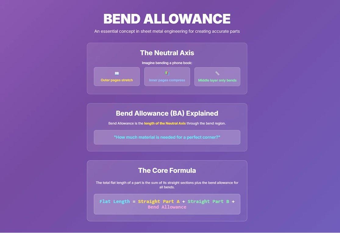
Imagine bending a thick phone book. The outer pages stretch—and might even tear—while the inner pages are compressed and crinkle. Somewhere in between these extremes lies a magical layer where the paper is neither stretched nor compressed, only reshaping as the bend occurs.
In sheet metal engineering, this layer is called the "neutral axis."
In simple terms, bend allowance is the actual length of this neutral axis through the bend region.
It answers the core question for every designer and engineer: “To achieve a perfect 90° bend, exactly how much material do I need to reserve for this corner?” That reserved length is the bend allowance.
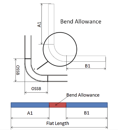
Therefore, the final flat length of a part is the sum of all the straight sections plus the total bend allowance for all bends.
Flat Length = Straight Edge A + Straight Edge B + Bend Allowance (BA)
For decades, the concept of bend allowance has been a cornerstone of metal fabrication, evolving alongside advances in materials and bending technologies. Historically, fabricators relied on empirical data and hands-on experience to estimate bend allowance.
Today, with the advent of Computer-Aided Design (CAD) and Computer-Aided Manufacturing (CAM), this process has become far more precise and data-driven. Modern workshops use advanced software to calculate bend allowance, factoring in material type, thickness, bend angle, bend radius, and inside radius.
2. Importance of Bend Allowance in Production
The importance of accurate bend allowance calculations cannot be overstated. They ensure that the final product’s dimensions are exactly right—a critical requirement for parts that must fit together seamlessly in assembly. Incorrect bend allowances can result in parts that are too short or too long, leading to costly rework or scrapping.
(1) The “Profit Eater”
A wrong bend allowance means the sheet’s flat pattern is incorrect from the start. The outcome? Either a useless part that won’t assemble, or a flawed component requiring time-consuming fixes. Every millimeter of error relentlessly consumes your material budget and profit margin.
(2) The “Productivity Wrecker”
Picture a high-speed automotive assembly line brought to a halt because a bracket is off by just 0.5 mm, preventing dozens of subsequent parts from fitting. Production rhythm is disrupted, and delivery schedules are delayed. Accurate bend allowance is the foundation of efficient, large-scale manufacturing.
(3) The “Lifeline of Quality”
In certain industries, precision isn’t just “better”—it’s mandatory.
- Aerospace: The accuracy of a satellite’s solar panel bracket directly determines whether it can deploy in space.
- Consumer Electronics: The subtle curvature of a smartphone’s metal frame is key to both waterproofing and the precise arrangement of internal components.
- Medical Devices: A precisely bent surgical instrument can influence the success or failure of an operation.
Mastery of bend allowance is, in many ways, a defining factor of a manufacturing company’s core competitiveness.
3. Practical Applications of Bend Allowance
Bend allowance is used in various industries, each with its unique requirements and challenges. Here are a few practical applications:
- Automotive IndustryIn the automotive sector, bend allowance is critical for producing components such as chassis parts, brackets, and exhaust systems. Accurate calculations ensure that these parts fit together correctly, contributing to the overall safety and performance of the vehicle.
- Construction Industry: For construction equipment, precise bend allowance calculations are essential for producing structural components that can withstand heavy loads and harsh conditions. This includes beams, supports, and frames used in buildings and infrastructure projects.
- Consumer Electronics: In the consumer electronics industry, bend allowance is used to create enclosures and frames for devices such as smartphones, laptops, and tablets. These components require high precision to ensure proper assembly and functionality.
- Medical Devices: Medical device manufacturers rely on accurate bend allowance calculations to produce components such as surgical instruments and implants. These parts must meet strict regulatory standards and perform reliably in critical applications.
II. What Is Bend Allowance?
1. Definition
Bend allowance is an important factor in achieving accurate results in press brake bending. The metal sheet undergoes stretching on the outside and compression on the inside due to the forces of tension and pressure during the bending process.
Therefore, it is necessary to consider both bend allowance and bend deduction in the flat pattern of the workpiece to achieve the final accurate bending result. Both bend allowance and bend deduction are used in determining the dimensions of the flat workpiece drawing.
Bend allowance refers to the length of the neutral axis between the bend lines, and it is the length added to the flange length to get the bend allowance. The value of bend allowance is calculated as the difference between the total flat length and the total flange length of the workpiece in the flat pattern.
2. Bend Allowance vs. Bend Deduction vs. K-Factor
In the sheet metal world, these three terms are the Bermuda Triangle for newcomers—and even seasoned professionals occasionally get them mixed up. They are simply three different perspectives on the same physical phenomenon, serving different calculation logics.
(1) K-Factor
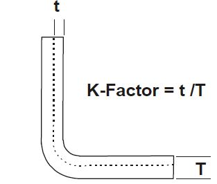
This is the physical foundation. It’s a dimensionless ratio (generally between 0.3 and 0.5) defining exactly where the neutral axis lies through the thickness of the material. It answers: “Where exactly is that magical, stretch-free, compression-free layer hiding?”
(2) Bend Allowance
This is the additive logic. As described earlier, it calculates the actual arc length of the neutral axis for the bend. It answers: “How much material do I need to add to create this bend?”
(3) Bend Deduction
This is the subtractive logic. It assumes two straight edges meeting at a theoretical sharp corner, then determines how much length to subtract from that total to account for stretching in the bend area. It answers: “To get the correct flat pattern, how much length should I cut off from the theoretical corner?”
The quick-reference table below will help you clearly distinguish their relationships:
| Feature | Bend Allowance (BA) | Bend Deduction (BD) | K-Factor |
|---|---|---|---|
| Core Definition | The actual arc length of the neutral axis in the bend region. | The value subtracted from the total length at the theoretical apex to account for material stretch in the bend. | A dimensionless ratio defining the location of the neutral axis within the material thickness. |
| Calculation Logic | Addition model: straight edge + straight edge + BA = flat length | Subtraction model: (outside dimension + outside dimension) − BD = flat length | Physical parameter: the essential input value used for calculating BA and BD. |
| Problem It Solves | “How much extra material is needed for this bend?” | “How much material needs to be subtracted at this apex?” | “Where is the neutral axis located within the material thickness?” |
| Application Context | The most intuitive choice when starting from internal part dimensions and building the flat pattern step by step. | More efficient and practical when back-calculating the flat length from the part’s external profile dimensions. | The prerequisite for all precise calculations. Determined experimentally or via empirical data, it is the theoretical starting point. |
| Relationship to Flat Length | Directly added to the straight-edge lengths. | Subtracted from the total length measured from the virtual vertex. | Indirect effect: it determines BA and BD values, thereby influencing the final result. |
3. Key Parameters
To calculate the bend allowance, the following key parameters are needed: plate thickness, bending angle, internal radius, K factor, and others.
1. Thickness
Thickness refers to the thickness of the metal sheet and is a crucial parameter in the bending process. The thickness directly affects the bending force required and the calculation of bend allowance. Thicker sheets require more bending force and are more prone to spring back during bending. The thickness is usually measured in millimetres (mm) or inches (in), not by the gauge number.
2. Bend Angle
The bend angle refers to the angle formed by the metal sheet during the bending process. This angle determines the final shape and function of the product. The size of the bend angle affects the calculation of bend allowance because different angles result in varying degrees of stretching and compressing of the metal sheet. Common bend angles include 90°, 120°, etc.
You will determine the bend angle based on your part's complementary angle. Before calculating, it is important to convert from the included angle to the complimentary angle. The Inside Radius will be the finished radius of the included angle.
3. Inside Radius
The inside radius refers to the radius of the bend on the inner side of the metal sheet after bending. The size of the inside radius directly impacts the bend allowance because it determines how the metal flows and deforms during bending.
A smaller inside radius results in greater material stretching and compressing, requiring more precise bend allowance calculations. The inside radius is usually denoted as R and measured in millimeters or inches.
4. K-Factor
The K-factor is a property of the material that you are bending, which can be used to describe the position of the neutral axis in the metal sheet during bending. The neutral axis is the layer that neither stretches nor compresses during bending.
In the field of sheet metal fabrication, the K-factor refers to the ratio of the neutral axis's location to the material thickness during bending. This value helps calculate bend allowances and deductions.
For most practical applications, the K-factor typically ranges between 0.3 and 0.5, depending on the type and thickness of the material. The K-factor plays a crucial role in bend allowance calculations as it helps determine the actual length change of the material during bending.
5. Springback
Springback refers to the phenomenon where the metal sheet tries to return to its original shape after bending. This is due to the elastic recovery properties of the material.
Springback affects the final bend angle, requiring multiple adjustments during the bending process to achieve the desired angle. The amount of springback depends on the type of material, thickness, and bend angle.
III. Bend Allowance Calculation
1. Bend Allowance Calculation Formula:
Where:
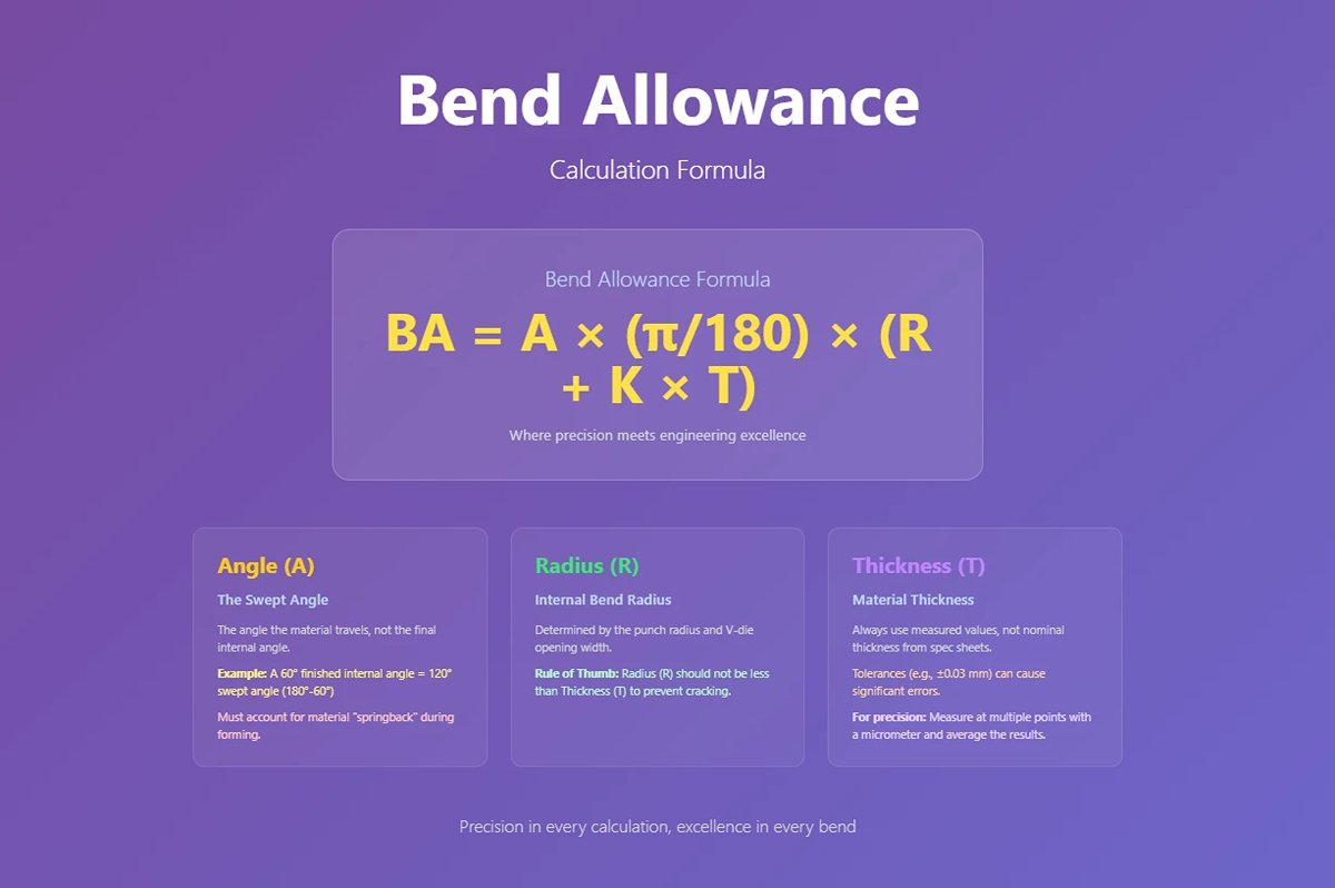
(1) Angle A
Represents the swept angle, not the internal angle.
The bend angle is the swept angle the sheet travels from flat to formed shape. For example, if the final internal angle is 60°, the bend angle is 180°−60°=120°. Due to springback, the tooling must often “overbend” to achieve the desired finished angle; actual forming angles should account for this compensation.
(2) Radius R
Determined by tooling and forming method.
In bottoming or coining, the internal radius is mostly determined by the punch radius; in air bending, it depends more on the V-die opening width. The rule of thumb is that R should not be less than T to prevent outer surface cracking, especially in high-strength materials.
(3) Thickness T
Measured values are preferred.
Sheet stock often carries tolerances of ±0.03 mm or more, which can quickly accumulate into significant errors. For precision components, measure at multiple points with a micrometer and average the readings instead of relying on nominal thickness.
The BA formula accounts for both the geometry of the bend and the material’s physical properties to determine the correct allowance.
(4) K-Factor
Defined as the ratio of the neutral axis location to sheet thickness, typically ranging from about 0.3 to 0.5. It varies significantly with tooling, material, and the R/T ratio:
| Condition | K-Value and Neutral Axis Trend |
|---|---|
| Soft materials (e.g., 5052 aluminum) | Neutral axis shifts toward the sheet’s mid-thickness; higher K-value |
| Hard materials (e.g., 304 stainless steel) | More pronounced compression zone; neutral axis moves closer to the inside surface; lower K-value |
| Large radius bend | K-value approaches 0.5 |
| Sharp angle bend | K-value drops significantly |
The most accurate method is to perform a test bend using the exact same material, tooling, and process conditions you will employ, then back-calculate the K-factor. By measuring the flange dimensions, internal radius, and total flat length of the test piece, you can reverse-engineer a shop-specific “magic number.” This step transforms external data into in-house know‑how.
2. The Bend Allowance Calculator is:
Miño, L. Bend Allowance Calculator. Available at: https://www.omnicalculator.com/physics/bend-allowance. Accessed: Jun 19, 2024.This calculator works as a bend deduction calculator as well.
3. Alternative Formula Representation
Another useful formula for bend allowance is:
Here, ( Ir ) represents the inside bend radius, and ( Mt ) represents the material thickness. This formula is often used in complementary bend angle calculations.
Practical Example
Let's calculate the bend allowance using our formula. Consider a bend with the following parameters:
- Bend angle: 90 degrees
- Inside radius (( r )): 0.25 inches
- Material thickness (( T )): 0.25 inches
- K-factor (( K )): 0.446 (a common value for mild cold-rolled steel)
First, convert the angle to radians:
Then, find the neutral axis position:
Finally, multiply these values to get the bend allowance:
IV. Sheet Metal Bend Allowance Chart
The largest variations come from the materials themselves. Protective coatings, variations in the alloy and thickness, and many other small factors all add up to give you bend allowances that are unique to your operation.
This bend allowance chart will get you close enough for most applications and may not require fine-tuning. However, if you are truly dedicated to precise bending, download the excel chart and begin plugging in your own values.
The below Microsoft Excel chart is for even numbered gauges 8 through 24 and has a default K-Factor of .33 for each.
1. Calculation Example
Bend allowance is important because it gives us the information to cut sheet metal to produce a bent metal piece accurately. Let's walk through a real-world example to illustrate how to calculate the bend allowance.
(1) Example Parameters:
- Material: Mild Steel
- Thickness (T): 0.125 inches
- Inside Radius (R): 0.250 inches
- Bend Angle (A): 90 degrees
- K-Factor (K): 0.42
(2) Step-by-Step Calculation:
1) Convert Bend Angle to Radians:
2)Apply the Bend Allowance Formula:
3)Result:
The bend allowance for a 90-degree bend with a material thickness of 0.125 inches, an inside radius of 0.250 inches, and a K-factor of 0.42 is 0.475 inches.
V. Comparison: Bend Allowance vs. Bend Deduction
1. Bend Deduction
(1)Definition
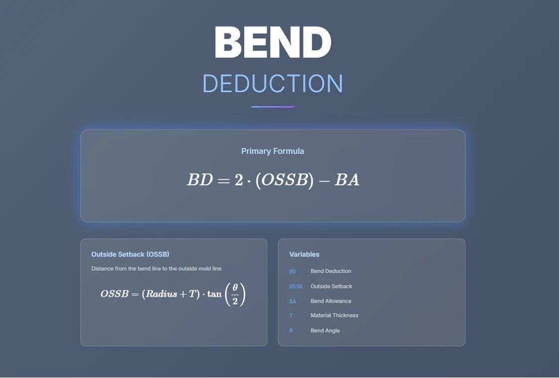
Bend deduction (BD) is the amount subtracted from the total flange lengths to determine the flat pattern length. It accounts for material compression and stretching during bending.
(2)Purpose
Used when designing flat patterns to ensure precise dimensions after bending.
(3)Formula
BD =2⋅(OSSB)−BA
OSSB (Outside Setback): Distance from the bend line to the outside mold line, calculated as:
2. Key Differences
| Aspect | Bend Allowance | Bend Deduction |
| Definition | Arc length along neutral axis | Difference between flange lengths and flat length |
| Purpose | Adds material for bending | Subtracts material for accurate flat patterns |
| Application | Flat pattern development | Adjusting flange lengths |
3. Practical Scenarios for Each Method
(1)When to Use Bend Allowance
1)Preferred when:
- The focus is on determining accurate flat patterns by adding elongation caused by bending.
- High precision is required for flange dimensions, such as in aerospace or medical device manufacturing.
2)Example:
A simple L-bracket with a bend angle of 90°, inside radius of 3 mm, material thickness of 2 mm, and K-factor of 0.42. The bend allowance ensures that the flat pattern accounts for material elongation.
(2)When to Use Bend Deduction
1)Preferred when:
- The design starts with known flange lengths, and the goal is to calculate how much material to remove from the total length for a correct flat pattern.
- Inside radius precision is critical, such as in tight tolerance applications like automotive chassis components.
2)Example:
A part with two flanges measuring 50 mm and 100 mm, an inside radius of 5 mm, and a bend angle of 120°. Using bend deduction helps determine how much to subtract from the total flange lengths to achieve an accurate flat pattern.
VI. Beyond Charts: Real-World Optimization Strategies
In true mass production, charts and formulas are merely the starting point—the decisive factors often lie within the subtle “gray areas” of detail. Here, both the character of the material and the temperament of the equipment come into play, along with nuanced process trade-offs. Master these strategies and you’ll evolve from simply calculating to truly controlling the outcome.
1. Controlling Springback: How to Predict and Accurately Compensate
Springback is the natural reaction of material releasing internal stresses after bending—much like a bamboo strip wanting to spring back after being pressed. Ignore it and your dimensions will be off; control it and you can produce precision parts in one shot.
(1) Core Factors Influencing Springback
1)Material properties: Higher yield strength and lower elastic modulus (e.g., high-strength steel, aluminum alloys) → greater springback.
2)Geometry: The thinner the sheet and the larger the R/T ratio, the greater the springback.
3)Bend angle: The larger the swept angle, the more springback occurs.
4)Forming method: Air bending produces the most springback, bottoming is moderate, and coining produces virtually none.

(2) Three Levels of Compensation
| Method | Description |
|---|---|
| Empirical (overbend) | Based on experience or trial bends, set the machine angle slightly past target—for example, aim for 88° when you need 90°—so the material “springs back” into place. |
| Process Method | Increase punch penetration depth or prolong dwell time to ensure deeper material plastic deformation and reduced springback. |
| Digital Simulation | Use Finite Element Analysis (FEA) during the design phase to predict springback and pre-compensate in process parameters, reducing the need for physical trial-and-error. |
2. The “Grain” Factor: Bending with vs. Against the Grain
During rolling, sheet metal develops an invisible grain direction—its “texture”—that has a direct impact on bending performance.
| Bend Direction | Definition | Advantage | Risk |
|---|---|---|---|
| Against Grain | Bend line runs perpendicular to grain | Maximum strength, high crack resistance | Requires high ductility; brittle materials risk cracking on large bends |
| With Grain | Bend line runs parallel to grain | Lower force requirements, easier forming | Higher likelihood of splitting along grain boundaries, reduced fatigue life |
Designs should prioritize structural bends against the grain direction. When bending with the grain is unavoidable, increase the bend radius to at least 1.5T to reduce stress concentration. Good engineering drawings specify grain direction, ensuring this critical detail is communicated to the shop floor and eliminating guesswork in layout.
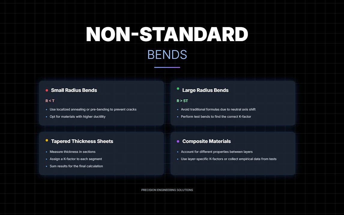
3. Handling Non-Standard Radii, Tapered Thickness, and Composite Materials
(1) Extremely Small Radius Bends (R < T)
Perform localized annealing or use pre-bending steps to reduce cracking risk; if necessary, opt for materials with higher ductility.
(2) Extra-Large Radius (R > 5T)
Avoid relying solely on traditional linear formulas; instead, prioritize performing test bends and adjusting the K‑factor accordingly. This is because the position of the neutral axis tends to shift closer to the midpoint of the sheet, introducing additional deviation.
(3) Tapered/Variable-Thickness Sheets
Measure thickness in sections and assign corresponding K‑factors per segment, then sum up the results for the final flat‑pattern calculation.
(4) Multi‑Layer Composite Materials
Simple thickness ratios no longer apply—you must account for the elastic–plastic differences between layers. Model using layer‑specific K‑factors, or collect empirical data directly from testing.
For parts with complex geometry and significant variation in material properties, finite element analysis (FEA) offers the most reliable method for predicting forming outcomes. By modeling material layer characteristics and process paths, you can foresee issues before trial production, allowing you to adjust designs and tooling parameters in advance—effectively intercepting high‑risk operations at the drawing stage.
True mastery goes beyond merely “calculating from charts.” It means transforming every uncertainty into a controllable variable through springback prediction, directional grain control, proprietary K‑factor calibration, and targeted process innovation. This is the qualitative leap from simply bending metal to bending with accuracy and consistency.
VII. Common Error Diagnostics and Solutions
In the sheet‑metal bending workflow, even the slightest deviation at any stage can cascade like a virus, amplifying until the finished product emerges as a costly reject. This chapter serves as a practical “quality firewall” to help you quickly pinpoint root causes and apply precise remedies.
1. The Five Root Causes of Dimensional Inaccuracy
Dimensional errors rarely originate solely from a single bending operation; more often, their seeds are sown much earlier—during design, material selection, or measurement.
(1) Incorrect K‑Factor Assumptions
Treating the CAD‑default value of 0.447 as a “universal key” is essentially building your design on someone else’s factory data. Machine rigidity, tooling geometry, and material ductility all subtly shift the true K‑factor.
- Prevention: Perform standardized test bends using your own equipment and materials to build an in‑house K‑factor database.
(2) Ignoring Batch‑to‑Batch Material Variations
Even within the same grade, personality differs: a thickness increase of just 0.03 mm or a 5 HB rise in hardness can alter springback behavior.
- Prevention: Always inspect incoming materials for thickness and hardness; for critical batches, fine‑tune process parameters after a test bend.
(3) Inaccurate Measurement Tools or Poor Technique
Expired calibration, burrs at measurement points, or parallax errors when reading can all quietly breed dimensional deviations.
- Prevention: Regularly calibrate and certify all measuring instruments; deburr edges before measurement; have multiple operators cross‑verify critical dimensions.
(4) Die Wear Stealthily Increasing Bend Radius
Wear on punch tips and V‑die shoulders is an invisible killer of accuracy.
- Prevention: Routinely measure the die radius and plot a wear curve; when thresholds are exceeded, regrind or replace immediately.
(5) Inaccurate Springback Compensation
Basing adjustments on gut‑feel, such as “just add two degrees,” is gambling, not process control. Over‑ or under‑compensation will skew the final angle.
- Prevention: Determine compensation values for each material, thickness, and bend angle through test bends; record them in the process sheet—ban replacing data with undocumented tribal knowledge.
These error sources often don’t act alone—they accumulate. Even a 0.1 mm deviation at each stage can snowball in multi‑bend assemblies, eventually breaching tolerance limits.
2. Troubleshooting: Preventing Cracks, Wrinkles, and Angle Errors
| Common Defect | Root Cause Analysis | Quick Fix |
|---|---|---|
| Bend cracking | Bend radius too small; unfavorable grain orientation; poor material ductility | Increase R/T ratio; re‑nest so bend is perpendicular to grain; anneal or switch to high‑ductility material |
| Surface wrinkling | Inner‑face compression instability; flange too long or sheet too thin | Use thicker sheet; increase internal radius; optimize die design (add pressure pad / draw bead) |
| Insufficient/inaccurate angle | Incorrect springback compensation; poor equipment/die accuracy | Precisely set over‑bend angle; use bottoming/coin bending to lock the angle; calibrate press brake and repair or replace worn dies |
The real shortcut to fixing defects isn’t simply cranking up parameters—it’s isolating the primary cause, then applying targeted corrections. Cracking and wrinkling stem from fundamentally different stress states; treating them the same way will only compound the damage.
3. Quality Control
Quality cannot be safeguarded merely by constant monitoring; you must build inspection standards into the process and maintain full traceability to prevent problems before they occur.
(1) Four‑Step Inspection Protocol
Inspect thickness, hardness, and grade for every batch; isolate any out‑of‑spec material immediately. First‑article inspection: after setup changes or first production run, confirm 100% of dimensions before mass production.
In‑process inspection: perform regular checks at set time or quantity intervals; correct deviations immediately if trends emerge.
Final inspection: verify dimensions and appearance (full check or sampling) as the last safeguard before shipping.
(2) Four Dimensions of a Traceability System
- Clear origin tracking: Record supplier, heat number, batch number, and material certificate.
- Unique identification: Assign each sheet and part a unique code (QR code/serial number).
- Process linkage: Tie the ID to machine number, process parameters, operator ID, and inspection data.
- Full visibility: Maintain a complete information chain from material receipt to product delivery.

The real value of traceability lies not in post‑failure blame, but in foresight and early correction. When data reveals that “Supplier B’s material has more consistent springback than Supplier A’s,” or that “Machine #3’s angle accuracy declines significantly after four hours,” you’ve already gained a decisive quality advantage over most competitors.
Ⅷ. FAQs
1. How does the K-factor affect bend allowance?
The K-factor significantly affects bend allowance by determining the position of the neutral axis during the bending process. It is a mathematical multiplier that reflects the material's properties, typically ranging between 0.3 and 0.5.
The K-factor adjusts the inside radius in the bend allowance formula, ensuring accurate calculations by accounting for the shift in the neutral axis. This adjustment is crucial for predicting the elongation that occurs during bending, thus enabling a precise layout of the flat pattern and achieving reliable results in metal bending operations.
2. What is the difference between bend allowance and bend deduction?
Bend allowance and bend deduction are crucial concepts in metal bending. Bend allowance refers to the length of material required along the neutral axis to form a bend, ensuring the correct total length of the workpiece. In contrast, bend deduction accounts for the material's elongation during bending, requiring a subtraction from the flat length to achieve precise final dimensions.
While both involve parameters like bend angle, inside radius, material thickness, and the K-factor, they serve different purposes: bend allowance adds to the flat length, whereas bend deduction subtracts from it, ensuring accurate part production.
3. How can I use a bend allowance chart for accurate metal bending?
To use a bend allowance chart for accurate metal bending, identify the key parameters such as material thickness, bend angle, and inside radius. These charts provide pre-calculated bend allowance values for common combinations of these parameters.
By referencing the appropriate values on the chart, you can determine the extra length needed for the bend without manual calculations. This ensures precision and efficiency in your bending operations, as discussed earlier. For more customized needs, use the provided formulas to calculate specific bend allowances based on your project requirements.
4. What tools are available for calculating bend allowance and bend deduction?
To calculate bend allowance and bend deduction for metal bending, several tools are available. Manual calculations can be done using specific formulas, while specialized software like SolidWorks Sheet Metal, AutoCAD, and Fagor Automation’s Sheet Metal Software offers automated calculations integrated into the design process.
Online calculators such as those from Omni Calculator and SendCutSend provide quick, user-friendly solutions. Additionally, bend allowance charts based on empirical data from suppliers and educational resources like instructional videos can aid in ensuring accurate and efficient calculations.
Ⅸ. Conclusion
The bend allowance and bend deduction are essential parameters for achieving accurate results in press brake bending. To obtain the correct dimensions of a flat workpiece drawing, both of these values must be taken into consideration.
The bend allowance refers to the length of the neutral axis between the bending lines, or in other words, the arc length of the bend, and is calculated as the difference between the total flat length and the total flange length of the workpiece in its flat pattern mode.
The bend deduction, on the other hand, is equal to the difference between the total flange length after bending and the total flat length. It is used to determine the flat pattern length of the sheet metal and the size of the workpiece.
When sheet metal goes through the bending process, the metal in the bend deforms and stretches. When this happens, your part's total length increases by a small amount. Likewise, when you're trying to develop the flat pattern, you have to subtract a portion from the desired part size to get the correct flat dimensions.
To calculate the sheet metal bend allowance, factors such as plate thickness, bending angle, internal radius, K factor, and others must be taken into account. The sheet metal bend deduction can be obtained once the bend allowance is known.
You can either use a formula or a bend allowance chart to calculate the bend allowance. For more information on bending and our press brake products, read our blog or contact our experts.
My company, ADH Machine Tool, not only offers press brakes but also panel benders, fiber laser cutting machines, shearing machines, and more. Our team of experts is available to help you with your needs.


