I. Introduction
Hydraulic press machines are widely used in industrial fields to efficiently perform heavy processing tasks. With the application of a small force, the closed liquid in the hydraulic cylinder generates a large compression force.
The hydraulic press machine was invented by Joseph Bramah in 1795 and uses a hydraulic lever instead of a mechanical lever. It features adjustable die space, stroke length, and applied pressure.
These machines can be used to process a variety of materials including metal, plastic, wood, rubber, and others. Applications of a hydraulic press include metal forming, molding, bending, forging, sheet drawing, cold extrusion, straightening, flanging, stamping, and powder metallurgy.
The hydraulic press machine is commonly used in the manufacturing of electrical appliances, automobile parts, rails, knives, and aircraft. This article provides a comprehensive overview of the definition, history, components, types, working principles, and applications of hydraulic press machines.

II. What Is A Hydraulic Press Machine?
A hydraulic press machine is a device that uses hydraulic fluid to generate a large amount of force on a small surface area for metal processing. Hydraulic presses range in size from small, such as relatively small bench press, to very large, such as 500-ton. Large hydraulic presses can be designed for low-tonnage applications, and small hydraulic presses can be designed for high-tonnage applications.
It is mainly composed of a frame, base, power system, and control system. A hydraulic press uses a hydraulic cylinder to produce a compressive force and operates based on Pascal's law. The principles of hydraulic force inherently allow for customization, flexibility, and creative engineering.
In the hydraulic press machine, the piston exerts pressure on the fluid, which in turn generates a mechanical force. The pressure generated by the piston is uniformly transmitted to all directions within the confined fluid, resulting in a uniform and smooth force being applied to the ram.
The hydraulic press machine is widely used in the industrial field for metal forming, straightening, and crushing. It can generate a high tonnage of up to 10000 tons and is commonly used for pressing materials together or apart, forming metal parts, and bending and straightening materials. One of the most commonly used machines for bending operations is the press brake. If you’re weighing your options, it’s essential to understand how different power sources can affect performance. For an in-depth breakdown, take a look at our comprehensive guide: Hydraulic Press Brake vs Electric Press Brake.
The hydraulic press depends on Pascal's principle, which states that when pressure is applied to a confined fluid, the pressure change occurs throughout the entire fluid.
Hydraulic presses play a major role in the fabrication, assembly, and production of components for machinery and parts for commercial and industrial products. It is typically used in metalworking industries for sheet metal operations such as drawing, deep drawing, punching, and blanking.
Types of Hydraulic Presses
H Frame Hydraulic Press Machine
An H-Frame Hydraulic Press is a machine with a distinctive H-frame structure, equipped with a pressure cylinder, pump, and movable support. This type of hydraulic press is equipped with a manual pump and is commonly used for small-scale production.
C Frame Hydraulic Press Machine
A C-Frame Hydraulic Press is designed with a C-shaped frame that offers better speed, accuracy, and guidance performance. This type of hydraulic press is more portable and is commonly used for fixing and assembling parts, disassembling components, or bearing installations.
C frame hydraulic presses are available in single column (C frame) and double column (D frame) models.
Four Column Hydraulic Press Machine
The Four-Column Hydraulic Press features two hydraulic cylinders and a central control system. The pressure and compression speed of this hydraulic press are adjustable, and it also has a semi-automatic circulation function.
It's possible to adjust the blanking pressure and working pressure, and the four-column hydraulic press can exert a significant amount of force on the workpiece.
Roll-frame Hydraulic Press Machine
The Roll-Frame Hydraulic Press is specifically designed for installing bearings, gears, and pulleys on axles and rollers. It can also be used for bearing calibration and pressing of shaft parts.
Hydraulic Straightening Press Machine
Straightening hydraulic presses are designed to align shafts, plates, and large weldments. By applying pressure to metal, these presses achieve the desired shape and alignment, ensuring metal components meet precise specifications and are free from warping or bending.
Tyre press
Designed specifically for the automotive and tire manufacturing industries, tyre presses are essential for the efficient assembly and disassembly of tires. They exert substantial force to mount and demount tires from rims, ensuring a secure and precise fit that is crucial for vehicle safety and performance.
King Pin Press
King pin presses are specialized tools used in the heavy-duty automotive sector for the removal and installation of king pins in trucks, buses, and other large vehicles. These presses enable precise and controlled force application, essential for maintaining the alignment and functionality of steering systems in heavy vehicles.
Arbor Press
Arbor presses are ideal for smaller jobs such as bearing removal, assembly, seating stamping, and repair of production jobs. Typically used for riveting, installing, configuring, and removing bearings, these manually operated presses offer precise control, making them suitable for small-scale and detailed tasks.
Air-Operated Hydraulic Press
Combining the ease of pneumatic systems with the power of hydraulics, air-operated hydraulic presses excel in tasks like riveting, punching, and bending, making them versatile tools in manufacturing. They utilize compressed air to push hydraulic fluid, creating pressure that is both efficient and easy to manage.
Double Acting Hydraulic Press
These presses are especially useful for repeatedly lifting and lowering heavy dies, ensuring consistent control and efficiency. They offer more lifting power than single acting presses, making them ideal for larger applications requiring a fixture or die to be mounted and returned consistently.
Compression Molding Press
Compression molding presses utilize two separate plates that compress material into the required mold. They are commonly used in the production of composite materials, plastics, and rubber components, where precise molding is necessary for quality and performance.
Each type of hydraulic press is purpose-built to meet the demands of particular applications and industries. For an in-depth look at the full specifications and performance features of our complete range, we invite you to download our Brochures.
III. History of Hydraulic Press Machine
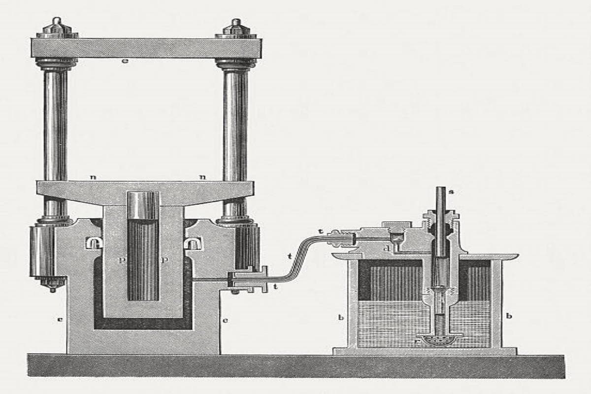
Hydraulic press technology has a rich history spanning thousands of years, and it focuses on fluid flow and control. It wasn't until the 18th century that the English inventor Joseph Brahma created the hydraulic press.
He developed the hydraulic press machine based on Pascal's principle. Interestingly, he also invented the toilet, which has greatly improved our daily lives. In its early days, the hydraulic press machine-generated pressing force through a basic hydraulic cylinder.
Today, the hydraulic press machine has been upgraded and is widely used in various applications, like agriculture and other fields. A hydraulic press machine can be selected to fit specific processes, materials, and scenarios.
IV. Main Parts of Hydraulic Press Machine
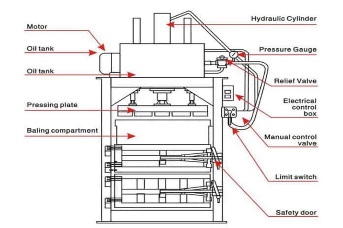
The basic structure of a hydraulic press machine consists of a frame, a working table, and a ram, and the key components work together to perform the pressing operation as follows:
- Hydraulic Pump: This component generates the hydraulic pressure required for the press. It converts mechanical energy into hydraulic energy.
- Hydraulic Cylinder: A hydraulic cylinder, which consists of a piston rod and a ram, serves as the machine's power source. The press cylinder is where the hydraulic energy is converted back into mechanical energy to perform the pressing action.
- Control Valves: These valves control the flow and direction of the hydraulic fluid, ensuring precise operation of the press.
- Hydraulic Fluid: The fluid transmits power throughout the hydraulic system. The choice of hydraulic fluid is crucial for the efficiency and longevity of the press.
- Reservoir: This is where the hydraulic fluid is stored. It also helps in cooling the fluid and removing air bubbles.
The hydraulic cylinder transforms the hydraulic system's fluid power into kinetic energy, which drives the ram. Oil is stored in an oil tank and is connected to the hydraulic cylinder's piston rod through pipes.
When the hydraulic oil is transmitted to the piston rod, the hydraulic cylinder creates pressure to drive the ram and process the material. The hydraulic press uses a motor to power the oil pump, which converts mechanical force into pressure.
A limit switch is used to adjust the height and thickness of the processed material, as well as to control the pressure applied to the workpiece by maintaining a set gap between the platens. The machine's relief valve releases any excess pressure in the pressed metal plate.
The manual control valve allows for adjustment of the pressure applied by the slider on the workpiece. Finally, the electrical box controls the switches and joysticks of the machine through wiring and circuit connections.
V. How Does A Hydraulic Press Machine Work?
How a hydraulic press works? Now let us understand the fundamental principle of a hydraulic press here. Before we start, let's watch the video first:
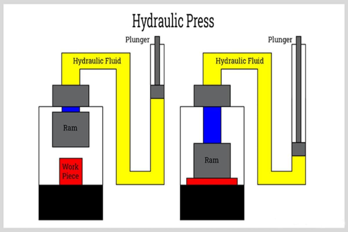
The secret behind a hydraulic press’s tremendous force multiplication lies in a centuries-old physical principle — Pascal’s Law.
This law states that any pressure applied to a confined, static fluid is transmitted equally and undiminished throughout the fluid and to the walls of its container.
In a hydraulic system, this principle is cleverly harnessed through the use of different-sized pistons to create an efficient force multiplier:
(1) Pressure Generation
The power system drives a small piston (input side), applying a relatively small force (F₁) to the enclosed hydraulic fluid. By the pressure equation P = F/A, this force creates a pressure P over the piston’s cross-sectional area (A₁).
(2) Pressure Transmission
In accordance with Pascal’s Law, this pressure P is instantly and uniformly transmitted throughout the entire hydraulic system — including to the underside of the larger output piston.
(3) Force Amplification
This same pressure P acts over the much larger cross-sectional area (A₂) of the output piston, thereby generating a proportionally greater output force (F₂).
The mathematical relationship is: P = F₁/A₁ = F₂/A₂, which means the output force F₂ = F₁ × (A₂/A₁).
This means the output-to-input force ratio is exactly equal to the ratio of the two piston areas. If the large piston’s area is 1,000 times greater than the small one’s, then applying a 1‑ton force can theoretically deliver a colossal 1,000‑ton thrust — the very foundation of mega-ton industrial power.
Picture a U-shaped tube filled with fluid — the left leg narrow (small piston A₁), the right leg wide (large piston A₂). Pressing the small piston down gently moves it a short distance, while the massive piston on the other side, though barely rising, can effortlessly lift a heavy-duty truck. This effect follows the law of energy conservation: force is amplified, but travel distance is reduced, keeping total work constant.
Once the hydraulic oil enters the piston, it generates a large amount of pressure, driving the ram and punch to apply force to the workpiece. The hydraulic press machine can generate a great deal of energy with minimal force.
VI. Maintenance and Care
Regular maintenance is essential for the optimal performance of a hydraulic press machine.
1. Key maintenance Tasks:
- Fluid Level Check: Regularly check and maintain the hydraulic fluid level to ensure efficient operation.
- Filter Replacement: Replace hydraulic filters periodically to prevent contamination and ensure clean fluid circulation.
- Seal Inspection: Inspect and replace seals to prevent leaks and maintain pressure.
- System Bleeding: Bleed the system to remove any trapped air, which can affect the performance of the press.
2. Troubleshooting Tips:
If the machine doesn't start, check the power supply and safety interlocks. If the press operates but with reduced power, inspect the hydraulic fluid levels and pump functionality.
For inconsistent pressure, verify control valve settings and examine for possible air entrapment in the system. It might be necessary to bleed the system to remove any trapped air.
Common Issues and Solutions:
| Issue | Possible Cause | Solution |
| Inconsistent Pressure | Valves may be faulty | Adjust or replace valves |
| Noisy Operation | Air in the hydraulic lines | Bleed the lines to remove air |
| Overheating | Insufficient fluid cooling | Check cooling systems and fluid flow |
VII. Safety Features
Modern hydraulic press machines are equipped with various safety features to protect operators and ensure safe operation:
- Emergency Stop Button: Allows operators to stop the machine in case of an emergency quickly.
- Safety Guards: Physical barriers that prevent accidental contact with moving parts.
- Pressure Relief Valves: These valves prevent overpressurization, which can damage the machine and pose safety risks.

VIII. Application Examples
1. Automotive Lightweighting
Forming High-Strength Steel (HSS) and Aluminum Alloys for New Energy Vehicle Components
One of the biggest hurdles to widespread adoption of electric vehicles is so-called “range anxiety.” To combat this, reducing vehicle body weight has evolved from a desirable option to an essential competitive priority. However, the advanced materials that enable lightweighting — such as High-Strength Steel (HSS), Ultra-High Strength Steel (UHSS), and aluminum alloys — present unprecedented challenges in forming processes.
(1) Core Challenges
1)The "stubborn" nature of high-strength steel
These materials possess exceptional strength but low elongation, making them prone to cracking under the instantaneous impact of conventional mechanical stamping. They also exhibit significant springback, making it difficult to maintain dimensional accuracy after forming.
2)The "delicate" behavior of aluminum alloys
While light in weight, aluminum alloys have an extremely narrow forming window; even slight deviation during stretching can cause wrinkling or tearing, requiring ultra-precise control over both pressure and speed.
(2) How the Hydraulic Press Overcomes These Issues
A hydraulic press is the ideal “tamer” for these unruly materials, thanks to its programmable force–displacement curves and ability to maintain constant force throughout the stroke.
1)The “slow-motion mastery” of deep drawing
For complex automotive components such as B-pillars and rocker panels, a hydraulic press can execute a finely tuned cycle of “rapid approach – slow draw – dwell – rapid return.” In the critical stretching phase, the ram descends slowly and steadily, giving HSS sheets ample time for plastic flow, thus avoiding stress concentrations that lead to cracking. This approach persuades the material into shape rather than striking it — a finesse mechanical presses cannot match.
2)Beating springback with the “shape-locking” magic of dwell
At the end of the stroke, the hydraulic press can apply a precise dwell period of sustained high pressure. These few seconds release residual stresses within the material, dramatically reducing springback in both HSS and aluminum alloys, and ensuring dimensional stability and consistency.
3)Coordinated performance with a hydraulic cushion
Advanced hydraulic stamping presses are typically equipped with CNC-controlled hydraulic cushions, which provide a dynamically adjustable and precisely measured “lifting force” (blank-holding force) on the edges of the sheet during the drawing process. This ensures that the material flows evenly into the die cavity, fundamentally eliminating the risk of wrinkling at its source.
In the quest for lightweight automotive design, the hydraulic press is far more than just another piece of processing equipment—it is the strategic cornerstone for the application of advanced materials. Without its precisely controlled force and speed, there would be no high-strength, high-safety lightweight bodies, and without those, no long-range, high-performance new energy vehicles.
2. Aerospace
Precision forging of titanium and high-temperature alloys
In aerospace, component requirements are the Mount Everest of industrial manufacturing: exceptional strength, heat resistance, fatigue resistance, and absolute reliability. Titanium alloys and high-temperature nickel-based alloys—used in critical load-bearing parts such as aircraft landing gear, engine turbine discs, and integrated fuselage frames—are among the most difficult materials on Earth to process.
(1) Core Challenges
1)Enormous resistance to deformation
These materials retain extremely high strength even at elevated temperatures, requiring tens of thousands of tons of overwhelming force to make them yield.
2)Narrow process window
Their forging temperature range is extremely narrow; even a slight deviation can degrade the internal metallurgical structure, causing catastrophic performance loss.
3)Relentless pursuit of optimal microstructure
Forging is not just about shaping; its deepest purpose is to refine grain size, eliminate internal defects (such as casting porosity), and form an ideal fiber flow pattern through plastic deformation—yielding unmatched comprehensive mechanical properties.

(2) The Hydraulic Press Advantage
In this domain, large-scale hydraulic forging presses are the undisputed tool of choice.
1)Platform for isothermal forging
The slow, steady pressing speed of a hydraulic press allows the die and billet to remain at an optimal, constant forging temperature throughout deformation—an approach known as isothermal forging. This process lets the metal flow smoothly, completely filling intricate die cavities to produce near-net-shape forgings, greatly reducing costly post-forging machining.
2)Deep microstructural transformation
Unlike the surface impacts of a forging hammer, the immense force of a hydraulic press penetrates throughout the entire billet—even those weighing tens of tons—achieving uniform plastic deformation from surface to core. This consolidates microscopic voids and aligns metal grains with the part’s load path, creating a flawless “forging flow line.” Such internal structural refinement is the foundation for the exceptional fatigue life and reliability of aerospace components.
In aerospace, the hydraulic forging press acts as the ultimate metallurgist—imparting not just shape, but extraordinary intrinsic properties. Whether or not a nation can field a large-scale hydraulic press exceeding ten thousand tons directly reflects its strategic capacity to manufacture advanced aero engines and large aircraft.
3. Renewable Energy
Compression of fuel cell graphite plates and molding of wind turbine blade composites
In response to climate change, the global energy mix is shifting rapidly toward renewables. Hydrogen fuel cells and wind power are two major pillars of this transition, and mass-producing their core components cost-effectively is impossible without the support of hydraulic presses.
(1) Hydrogen fuel cell bipolar plates
Bipolar plates are the “backbone” of a fuel cell stack, etched with highly intricate flow fields. They require materials—often graphite-resin composite powders—that achieve highly uniform density, excellent conductivity, and complete internal integrity after pressing.
Hydraulic presses deliver exceptionally consistent planar pressure and precise closed-loop pressure control. Multiple pressure sensors combined with a servo-hydraulic system ensure equal pressure distribution across the entire die surface, guaranteeing uniform plate performance. Their precise dwell capability ensures complete curing of the resin matrix.
(2) Large wind turbine blades
Modern wind turbine blades can exceed 100 meters in length, fabricated by laying up glass fiber, carbon fiber, and other composites, then heating and curing them in massive molds. This requires prolonged, large-scale, and uniform pressure to remove voids, impregnate fibers, and ensure structural integrity.
Extra-large hydraulic presses designed specifically for this sector provide unmatched working table dimensions and the ability to maintain stable pressure over long curing cycles. They ensure that throughout the many hours of curing, both pressure and temperature remain within tightly controlled process parameters—critical to producing high-quality, high-reliability large composite structures.
In renewable energy manufacturing, hydraulic presses are key to both scaling up production of precision components and achieving one-piece molding of massive structures. They ensure that everything from microscopic fuel cells to gigantic wind turbine blades delivers the performance and reliability needed to accelerate clean energy adoption.
4. Emerging Applications
For decades, the hydraulic press has been viewed as a symbol of “traditional” industry. Yet the deeper truth is that it is not only the foundation of established manufacturing but also a catalyst and finisher for bringing frontier technologies from the lab into commercial production.
(1) The “final step” in 3D printing
Hot Isostatic Pressing (HIP): Metal parts produced by additive manufacturing often contain minute internal voids and residual stresses, limiting their use in critical load-bearing applications.
HIP—essentially a hydraulic press using a specialized gaseous medium—applies uniform, ultra-high gas pressure at elevated temperatures to completely eliminate internal microscopic defects, driving density to nearly 100%. This can even result in performance surpassing that of conventionally forged components. Here, hydraulic principles serve as the “finishing move” that enables additively manufactured parts to reach their full potential.
(2) The “universal experimental platform” for new materials
Whether it’s bulk metallic glass, high-entropy alloys, or novel ceramic matrix composites, the forming processes for these future materials remain experimental. They often demand unconventional and highly demanding combinations of pressure, temperature, and time.
Thanks to its unparalleled flexibility and programmability, the hydraulic press is the go-to platform for scientists and engineers exploring such processes. By precisely controlling every process parameter, they can unlock the true potential of these materials, paving the way toward industrial application.
The enduring relevance of the hydraulic press stems from its mastery over one of the most fundamental physical quantities—force itself. No matter how manufacturing evolves—from subtractive to equal-material to additive processes—so long as shaping and modifying matter require precisely controlled, high-intensity pressure, the hydraulic press will remain indispensable. Today, it is crossing boundaries and empowering the cutting edge of the Industry 4.0 manufacturing revolution.
IX. Comparing Hydraulic, Mechanical, and Servo Presses
1. The Ultimate Performance Matrix Comparison
The single most fundamental—and impossible to replicate—competitive edge of the hydraulic press lies in its ability to deliver and stably hold 100% of its rated force at any point along the ram’s full stroke. This is not just a technical detail; it’s a strategic advantage that makes it the sole viable choice for a wide range of advanced forming processes.
(1) Mechanical press
Its power originates from a flywheel’s inertia, amplified through a crank-and-rod mechanism. This setup means maximum rated force is only available in an extremely narrow window near the bottom dead center at the end of the stroke. Once the ram moves beyond this point, force drops off sharply, almost exponentially.
As a result, for processes requiring long strokes and sustained high pressure to allow full material flow—such as deep drawing automotive body panels—a mechanical press is almost entirely unsuitable.
(2) Servo press
Although its core drive is a high-precision servo motor, most servo presses are structurally still “servo-driven mechanical presses.” While their force output curve is programmable, the peak force point is still limited by mechanical geometry—again, typically concentrated near bottom dead center.

(3) Hydraulic press
Its force is generated directly from incompressible hydraulic oil. In accordance with Pascal’s law, as long as the hydraulic pump continues to supply pressure, the hydraulic cylinder can deliver its rated tonnage consistently at any point in the stroke—whether it’s just making contact with the workpiece, midway through the stroke, or at the endpoint—and can maintain that pressure for as long as the process requires.
This unique ability to deliver full force throughout the entire stroke gives hydraulic presses an undisputed edge in processes such as deep drawing, precision molding, and heavy forging.
Rather than striking with the instantaneous “hammer blow” of a mechanical press, it applies a steady yet powerful pressure that coaxes metal or composite materials into plastic flow. This greatly reduces the risk of tearing, wrinkling, or springback in demanding forming operations, ensuring exceptionally high yield rates and outstanding part quality.
To quantify the differences among the three types, the table below presents a clear comparison of key performance indicators (KPIs):
| Performance Indicator | Hydraulic Press | Mechanical Press | Servo Press |
|---|---|---|---|
| Force Control | Excellent: Full rated force available throughout the stroke; pressure precisely adjustable and can be held indefinitely — its core advantage. | Limited: Maximum force occurs only near bottom dead center; pressure varies sharply and uncontrollably during the stroke; cannot hold pressure. | Excellent: Torque closed-loop control via servo motor enables precise force programming, but peak force point is still constrained by mechanical structure. |
| Speed | Slower: Limited by hydraulic oil flow and pump displacement; cycle speed (SPM) generally the slowest of the three. | Fastest: Continuous high-speed rotation of flywheel allows extremely high strokes per minute (SPM in the thousands), making it king for high-speed, mass production. | Fast & Adjustable: Much faster than hydraulic, close to mechanical presses; slide speed curve is fully programmable, enabling optimized profiles such as “fast down – slow press – fast return.” |
| Accuracy & Repeatability | High: Excellent pressure control accuracy; however, due to oil compressibility and thermal variation, positional repeatability is lower than mechanical and servo presses. | Very High: Rigid mechanical structure gives extremely high repeatability at stroke endpoint, though the stroke length itself is fixed. | Ultimate: Servo motors allow micron-level positional closed-loop control; delivers the highest repeatability for both position and pressure among the three. |
| Flexibility & Versatility | Very High: Stroke length, pressure, and speeds (including changeover points) are easily adjustable to suit various die heights and processes. | Low: Fixed stroke length and single speed profile make it essentially dedicated to one process; costly and difficult to adapt to other applications. | Very High: Entire slide motion curve is fully programmable; can mimic mechanical link motion or perform hydraulic-like dwell, enabling one machine to handle diverse processes. |
2. Economic Considerations
An experienced decision-maker looks far beyond the purchase price, evaluating the total cost of ownership over the machine’s entire operational lifespan.
(1) Cost Comparison
| Cost Factor | Hydraulic Press | Mechanical Press | Servo Press |
|---|---|---|---|
| Initial Investment | Medium: Relatively simple structure; price generally falls between the other two. Costs rise significantly for large-tonnage or custom non-standard models. | Low: Most mature technology with high standardization; lowest entry cost of the three. | Highest: Expensive servo motors, large-capacity drives, and precision control systems make it the most costly upfront. |
| Energy Consumption | Highest: Traditional hydraulic systems keep the main motor and pump running continuously to maintain pressure, even when idle, leading to significant standby losses. | Low: Energy mainly stored in the flywheel; motor only replenishes what’s lost to friction and pressing, resulting in good efficiency. | Lowest: Motor supplies energy strictly on demand; power is used only when the slide moves, with near-zero consumption in standby, delivering exceptional energy savings. |
| Maintenance Cost | Medium: Fewer moving parts, but the hydraulic system (oil, seals, valves, pumps) requires regular professional maintenance, with potential leakage posing environmental and safety risks. | High: Numerous moving parts (flywheel, clutch, brake, gears) with many wear points; maintenance is labor-intensive, and failure of critical components can cause prolonged downtime. | Lowest: Virtually no mechanical wear components or hydraulic systems; maintenance is focused on electrical systems, which are highly reliable and require minimal upkeep. |
| Die Life | Long: Smooth hydraulic loading with no rigid impact reduces stress and wear on dies. | Short: The huge impact force at bottom dead center is a severe test for die edges and structure, resulting in the highest wear and failure rates. | Longest: Programmable “soft landing” greatly reduces impact when the slide meets the die, extending die life by 3–4 times. |
(2) Cost–Benefit Examples in Different Scenarios
1)High-volume, standardized, shallow stamping (e.g., standard washers, consumer electronics casings)
Best Choice: Mechanical Press
Decision Rationale:
In this scenario, speed equals profit. With unmatched stroke rates and the lowest upfront cost, mechanical presses can bring unit manufacturing costs down to a minimum. While they have higher energy and die wear costs, the sheer volume of production dilutes these expenses. Limited flexibility is not a significant drawback for single-product, large-scale runs.
2)Automotive inner/outer panels, complex structural parts involving deep drawing and forming
Best Choice: Hydraulic Press
Decision Rationale:
In such applications, process capability is paramount. Only the hydraulic press’s ability to deliver full force across the entire stroke can ensure high-strength steel or aluminum sheet undergoes complex drawing without tearing or wrinkling. This process-specific superiority outweighs considerations of speed and energy consumption. For heavy forging or composite material molding, hydraulics remain the only viable choice.
3)High value-added, multi-variety, small-batch, high-precision forming (e.g., precision auto parts, medical devices, premium appliances)
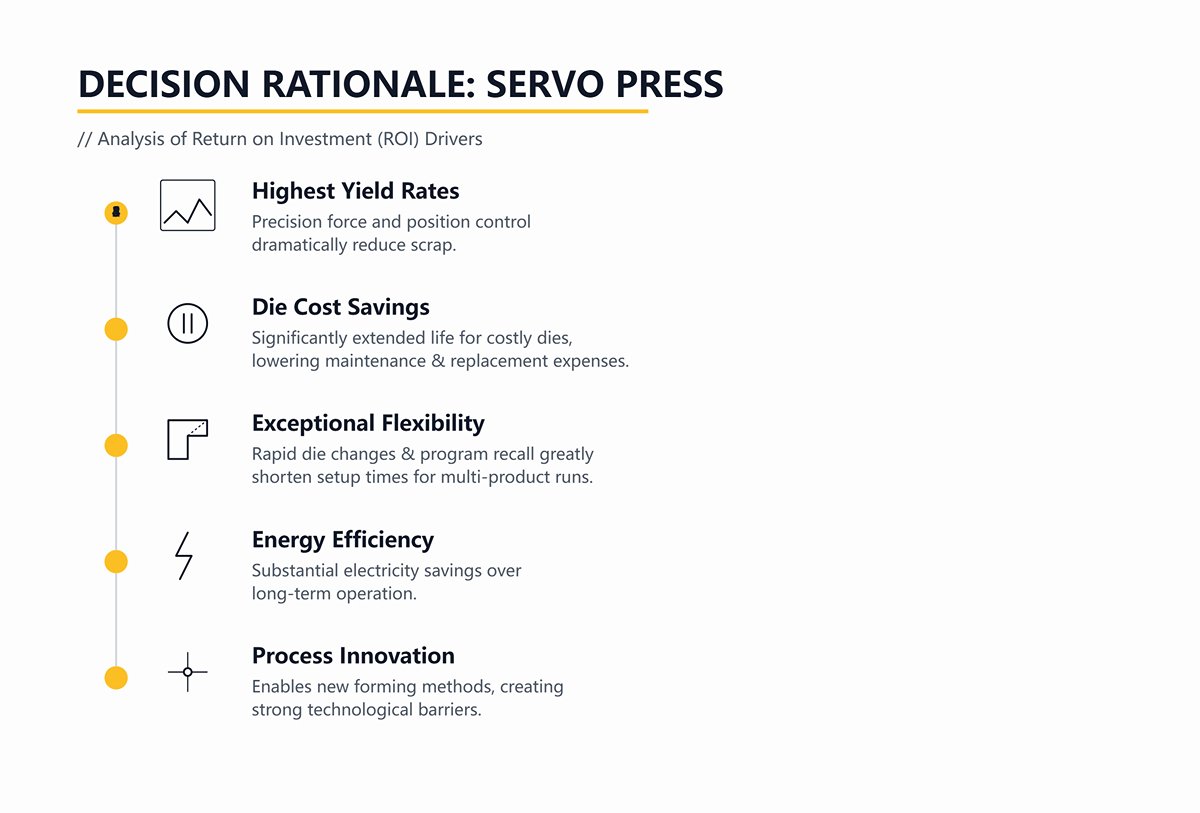
Best Choice: Servo Press
Decision Rationale
Although it demands the largest initial investment, a servo press can yield outstanding ROI through the following advantages:
- Highest yield rates: Precision force and position control dramatically reduce scrap.
- Die cost savings: Significantly extended life for costly dies, lowering maintenance and replacement expenses.
- Exceptional flexibility: Rapid die changes and program recall greatly shorten setup times for multi-product runs.
- Energy efficiency: Substantial electricity savings over long-term operation.
- Process innovation: Enables entirely new forming methods unattainable with traditional presses, creating strong technological barriers.
3. Servo-Hydraulic Systems
For years, hydraulic presses have carried the stigma of high energy consumption and comparatively limited precision. The advent of servo-hydraulic systems represents a technological breakthrough aimed at overturning this perception, marking the cutting edge of modern hydraulic evolution.
(1) Working Principle
A servo-hydraulic system is far more than just a servo motor paired with a hydraulic pump—it’s a revolutionary rethinking of system architecture. At its heart lies a high‑dynamic‑response servo motor that drives a fixed‑displacement pump with precision. The operating logic is nothing short of ingenious:
1)Power on demand—eliminating waste
The controller instructs the servo motor to drive the pump at exactly the speed and torque needed to deliver the required flow rate and pressure—no more, no less. When the ram is stationary or holding pressure, the motor speed can drop to a crawl or even stop entirely, eradicating the massive energy losses of traditional hydraulic systems that idle continuously or run oversized equipment for small tasks.
2)System simplification—boosting reliability
Because both flow and pressure are precisely managed by the servo motor, many of the complex, costly, and failure‑prone proportional and servo valve assemblies found in conventional hydraulics can be eliminated. The result is a much simpler design with faster response times and significantly higher reliability.
(2) Game‑changing advantages of servo‑hydraulics
1)Exceptional energy savings
Compared to conventional systems, servo‑hydraulics can cut energy consumption by as much as 50%–70%. In today’s era of rising energy costs, that’s like installing a profit‑generating “power‑saver” inside your plant.
2)High precision and rapid response
By combining the swift responsiveness and pinpoint control of a servo motor with hydraulic power, these systems elevate pressure and position accuracy by an order of magnitude—rivaling pure electric servo presses—and can execute far more complex process curves.
3)Quiet, cool operation
Since the motor often runs at low speed or remains idle, operational noise drops dramatically—potentially below 75dB. Reduced energy losses also help keep oil temperatures in check, enabling smaller or even no cooling systems, further cutting operating costs.
In essence, the servo‑hydraulic system is a perfect marriage of hydraulic muscle and servo finesse. It gives the time‑honored hydraulic press the raw power of a giant, the delicate control of fine needlework, and a green heart that beats with energy efficiency.
In competing with all‑electric servo presses, it has carved out an ideal “sweet spot” that balances cost, power, and performance—offering unmatched competitiveness, especially in medium‑ to large‑tonnage applications with demanding forming requirements.
Ⅹ. Conclusion
In the article, I have detailed the definition, history, components, types, working principles, and wide applications of hydraulic press machines. Understanding the working principles and different kinds of hydraulic press machines can help you make an informed decision about which machine is right for your needs.
As a manufacturer with over 40 years of experience in producing press brakes, shearing machines, and laser cutting machines, my company, ADH Machine Tool, is dedicated to providing high-quality, high-performance machine tools and equipment.
If you are looking for reliable metal processing solutions, contact our expert team. We are committed to offering you the best service and support. Visit our website now to learn more about our products and discover how our advanced equipment can enhance your production efficiency.
ⅩI. FAQs
1. How are hydraulic presses used in the automotive and aerospace industries?
Hydraulic presses are crucial in the automotive and aerospace industries for their ability to apply precise and powerful forces. In the automotive sector, they are used for forming and stamping body panels, manufacturing chassis components, producing interior and exterior trims, and assembly operations, ensuring high accuracy and minimal material waste.
In aerospace, hydraulic presses form advanced materials and components, perform hot forging and hydroforming, aid in assembly and testing, and assist in repair and maintenance. Their precision, high force capability, and efficiency make them indispensable for producing high-quality components that meet stringent industry standards.
2. Are there any unique or unconventional uses of hydraulic presses?
Yes, hydraulic presses have several unique and unconventional uses. They are employed in the creation of ceramics, simplifying blacksmithing and sword making, compacting daily essentials like makeup powders and pills, and aiding in waste disposal and recycling. Additionally, hydraulic presses are popular in viral video content, where they are used to crush various objects for entertainment.
They also serve in agriculture for equipment repair, in the building industry for concrete testing, and in custom precision manufacturing for aerospace and automotive industries, showcasing their versatility beyond traditional industrial applications.
3. What are the advantages of using different types of hydraulic presses?
The advantages of using different types of hydraulic presses lie in their versatility, consistent pressure delivery, and adaptability for various industrial applications. These presses can be customized for specific tasks, offering smooth and even pressure throughout the operation. Their simple design leads to low maintenance costs, while their ability to deliver consistent tonnage ensures reliable results.
Additionally, hydraulic presses are space-efficient and economically viable, with options like hydropneumatic systems providing enhanced efficiency and safety. This adaptability and reliability make hydraulic presses valuable tools across diverse manufacturing and industrial sectors.


