I. Introduction
In the 3D design of parts, the design dimensions must take into account the total range of allowable variations. The sheet metal part designers need to consider the range of possible product dimension changes during the sheet metal design process.
If the part dimension variation range is not suitable, such as if the tight tolerances, then a more precise manufacturing process is needed to ensure the accuracy of the finished product. Practical tolerances vary according to the design requirements.
Applying unnecessarily tight geometric tolerances can significantly extend lead times and increase manufacturing complexity and cost. On the other hand, if the sheet metal tolerances range is too large, it cannot guarantee the quality of the parts.
Hence, it's essential to determine an appropriate tolerance range for the sheet metal part size that takes into account both accuracy and cost. But what are these tolerances, and why are they so crucial in the world of sheet metal fabrication?
This guide will unravel the complexities of sheet metal tolerances, from understanding standard specifications like ISO 2768 and ASME Y14.5 to exploring how different materials like aluminum, stainless steel, and carbon steel affect these tolerances. Ready to master the art of precision in sheet metal manufacturing and learn how to optimize your processes? Let's dive in.
II. Fundamentals of Metal Tolerances
2.1 Definition of Metal Tolerances
Sheet metal tolerance refers to the specified range within which a part’s design dimensions may vary. The manufacturing tolerance range defines the upper and lower allowable limits for these variations. Tolerances are essential for ensuring accuracy and are widely applied in sheet metal fabrication.
The tolerance zone is the space between the upper and lower deviation limits. Looser tolerances have a wider zone, while tighter tolerances allow a narrower range, resulting in greater dimensional precision. As in machining or 3D printing, strict tolerances allow for finer control. For example, a hole dimension of 10 mm ±0.1 mm means its actual diameter must fall between 9.9 mm and 10.1 mm—the 0.2 mm span represents its tolerance band.
2.2 Why Are Sheet Metal Tolerances Important?
In sheet metal fabrication, tolerances aren’t just abstract numbers—they function as a “precision contract” that runs through the product’s entire lifecycle. Every tolerance symbol in the design phase is a strategic decision influencing future performance, cost, and manufacturability. They’re like a code embedded in the part’s “DNA” that determines whether it assembles smoothly, operates reliably, and enhances—or undermines—the brand’s reputation.
Proper tolerances ensure parts fit together precisely even after repeated assemblies, reducing wear, preventing looseness and vibration. Too loose, and you risk leaks, unstable fits, and customer complaints; too tight, and you can slow production, lower yield rates, and drive up costs.
2.2.1 Key Stages
Tolerances impact three critical stages of a product’s life cycle:
(1) Assembly Stage
Enables parts to align quickly and accurately, shortening assembly time and reducing the risk of rework.
(2) Usage Stage
Maintains operational stability and longevity, coping with variations in temperature, humidity, and load.
(3) End-of-Life Stage
Minimizes waste and replacement caused by premature part failure, enhancing overall lifecycle value.

A simple way to visualize this is to imagine tolerances as a “safety track” around the nominal size. The nominal size is the center line, and the upper and lower deviations are the guardrails—stay within them, and the part remains out of the danger zones for quality and function.
2.2.2 The “Tolerance Value Triangle” Decision Model
Every tolerance decision balances three competing factors: quality, cost, and manufacturability—what we call the “tolerance value triangle.” Each corner is vital, but you can’t maximize them all at once; raising one will inevitably shift the others:
(1) Quality
Tighter tolerances mean smoother assembly, more consistent performance, and reliable quality—cornerstones of great customer experience and brand value.
(2) Cost
As tolerances tighten, costs often rise exponentially—due to the need for precision equipment, extra inspections, more scrap handling, and slower production speeds.
(3) Manufacturability
Different manufacturing processes vary widely in their tolerance capabilities. The right tolerance lets production run smoothly and cost-effectively without resorting to high-end processes; overly tight tolerances may force equipment upgrades or extra steps, reducing throughput. Utilizing advanced equipment like a CNC Press Brake can help achieve tighter tolerances more efficiently, bridging the gap between quality and cost.
The key is to keep tolerances within the “comfort zone” of manufacturing—loose enough to lower costs, but tight enough to preserve performance. Striking this cross-functional balance is a core skill for top engineers and production managers alike.
2.2.3 Material Thickness Tolerances
The allowable tolerance range varies depending on both the material and its thickness. Below are common reference ranges:
| Material Thickness (mm) | Tolerance Range (mm) |
|---|---|
| 0.5 - 1.0 | ±0.1 |
| 1.0 - 2.0 | ±0.15 |
| 2.0 - 3.0 | ±0.2 |
| 3.0 - 5.0 | ±0.25 |
| 5.0 - 8.0 | ±0.3 |
2.2.4 Tolerances for Specific Materials
Different materials have distinct tolerance requirements during processing. For example:
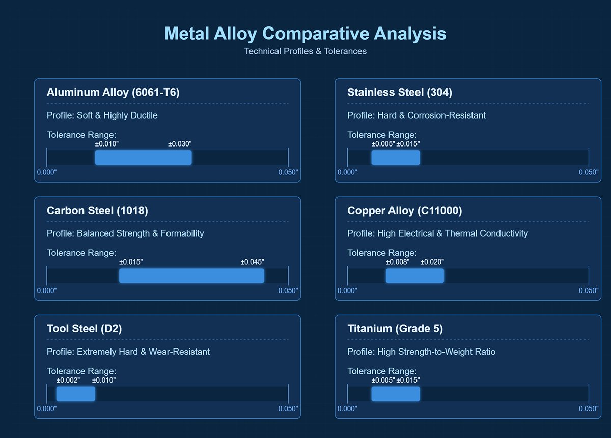
(1) Aluminum Alloy Tolerances
Due to its softness and high ductility (ease of forming), aluminum typically permits moderate tolerances. For instance, 6061-T6 aluminum is valued for its balance of strength and machinability, with common tolerances such as:
- General tolerance range: ±0.1 mm
- Specific alloy example (6061-T6): ±0.010 in to ±0.030 in
(2) Stainless Steel Tolerances
Known for its hardness and low ductility, stainless steel often requires tighter tolerances to maintain precision. For example, 304 stainless steel—favored for its corrosion resistance—typically has:
- General tolerance range: ±0.005 in to ±0.015 in
- Specific alloy example (304 stainless steel): ±0.005 in to ±0.015 in
(3) Carbon Steel Tolerances
Carbon or low-carbon steel offers a good balance of strength and formability, allowing moderate tolerances. 1018 low-carbon steel, often used in structural applications, generally maintains:
- General tolerance range: ±0.015 in to ±0.045 in
- Specific alloy example (1018 low-carbon steel): ±0.015 in to ±0.045 in
(4) Copper Alloy Tolerances
Copper alloys are prized for exceptional electrical and thermal conductivity and typically allow moderate tolerances. For example, C11000 copper, widely used in electrical applications, usually offers:
- General tolerance range: ±0.008 in to ±0.020 in
- Specific alloy example (C11000 copper): ±0.008 in to ±0.020 in
(5) Tool Steel Tolerances
Tool steels are extremely durable and hard, with low ductility that demands exceptionally tight tolerances. D2 tool steel, renowned for its wear resistance, typically features:
- General tolerance range: ±0.002 in to ±0.010 in
- Specific alloy example (D2 tool steel): ±0.002 in to ±0.010 in
(6) Titanium Tolerances
Titanium is renowned for its exceptional strength-to-weight ratio—a measure of strength relative to weight—and its low ductility, which also demands strict tolerance control. Grade 5 titanium, widely used in aerospace applications, generally exhibits the following tolerance standards:
- General Tolerance Range: ±0.005 inches to ±0.015 inches
- Specific Alloy Example (Grade 5 Titanium Alloy): ±0.005 inches to ±0.015 inches
As long as tolerances remain within a reasonable range, allowing for some dimensional variation can improve fit between components and potentially help reduce production costs.
Achieving extreme dimensional accuracy for tooling sizes requires specialized skills and equipment, which often increases machining time. For those looking to deepen their understanding, our guide on How to Improve Press Brake Bending Accuracy? offers practical insights. Therefore, defining practical tolerances during part design is crucial for ensuring the final product meets dimensional requirements.
Ⅲ. Types of Sheet Metal Tolerances
Sheet metal fabrication employs multiple types of tolerances, including flange length, width, sheet thickness, wall thickness, bends, curls, countersinks, hems, holes, slots, grooves, and embossed features. Parts should maintain uniform wall thickness throughout.
Tolerance grades determine dimensional accuracy and are classified into 18 levels according to international standards—the greater the tolerance value, the lower the manufacturing difficulty.
IT01 through IT4 are used for manufacturing measurement tools and gauges, IT5 through IT7 for precision engineering, and IT12 through IT14 for sheet metal fabrication or stamping.
Tolerance symbols are expressed as absolute values without any prefix, with smaller tolerance values indicating higher precision.
3.1 Dimensional Tolerances
Dimensional tolerances define the permissible size deviations for sheet metal parts. These tolerances ensure that parts fit and function as intended despite minor manufacturing variations.
(1) Linear Dimensions
Linear dimensional tolerances are essential for ensuring parts have correct length, width, and height. These tolerances vary by material thickness:
- For materials 0.5 to 1.0 mm thick, tolerances are typically ±0.1 mm.
- For materials 5.0 to 8.0 mm thick, tolerances may increase to ±0.3 mm.
(2) Angular Dimensions
Angular tolerances are critical for parts that require precise angles, such as those involved in bending operations with a press brake. These tolerances are typically around ±0.5°.
3.2 Geometric Tolerances
Geometric tolerances govern the form and positioning of part features, ensuring they maintain their intended shape and alignment during assembly.
(1) Form Tolerances
Form tolerances cover a variety of geometric attributes:
- Flatness and Straightness: Flatness ensures a surface is even, while straightness ensures an element follows a true line.
- Circularity: Ensures all points on a circular feature lie within a defined boundary.
(2) Positional Tolerances
Positional tolerances define the acceptable deviation of a feature’s location relative to a reference point. This is crucial for proper alignment of holes, slots, and other features during assembly.
3.3 Material Tolerances
Material properties significantly influence achievable tolerances in sheet metal fabrication.
(1) Material Thickness
Material thickness plays a key role in determining achievable tolerances. Thicker materials generally allow for looser tolerances, while thinner materials require more stringent control.
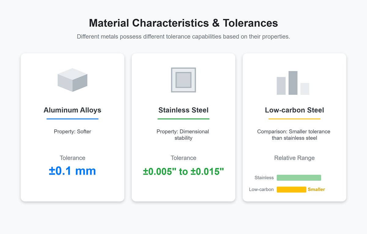
(2) Material Characteristics
Different metals possess different tolerance capabilities based on their properties:
- Aluminum alloys: Because they are softer, tolerances are generally around ±0.1 mm.
- Stainless steel: Due to its dimensional stability, tolerances range between ±0.005" and ±0.015".
- Low-carbon steel: Typically has smaller tolerance ranges compared to stainless steel.
Ⅳ. Common Tolerances in Mainstream Sheet Metal Processes
4.1 Laser/Punching Tolerances: Baseline and Limits of Precision
Laser cutting and CNC punching (NCT) mark the starting point in sheet metal fabrication, establishing the unshakable baseline of precision for a part’s two-dimensional profile. All subsequent processing accuracy builds on this. Laser cutting is celebrated for unmatched flexibility and high precision, while CNC punching delivers remarkable speed and cost efficiency for standard holes and specific shapes.
Modern fiber laser cutting machines set extremely high industry precision standards, typically maintaining tolerances between ±0.1 mm and ±0.3 mm. However, seasoned professionals know these figures vary with material thickness and part size.
(1) Tolerance Reference Table
| Material Type | Material Thickness (mm) | Typical Tolerance Range (mm) | Extreme Precision Tolerance (mm) |
| Steel, Aluminum, etc. | 0.5 - 3.0 | ±0.10 ~ ±0.20 | ±0.05 |
| >3.0 - 6.0 | ±0.20 ~ ±0.30 | ±0.10 | |
| >6.0 | ±0.30 and above | ±0.20 and above |
(2) Key Factors and Insights
1) Heat-Affected Zone (HAZ)
This is the "genetic defect" of laser cutting. Since laser cutting is essentially a "melt-and-blow" process, it leaves a minute heat-affected zone along the cut edges. In this zone, the metal’s microstructure and hardness have been altered—changes that are invisible to the naked eye but critical to consider in applications requiring secondary welding or strict hardness compliance.
2) Assist Gas
Gas does more than simply blow away molten slag—it actively reacts with the material. Oxygen cutting of carbon steel is faster and cheaper but oxidizes and blackens the cut edge. High-pressure nitrogen cutting (often called "bright cutting") is more costly, yet produces bright, oxidation-free edges with superior precision and surface quality.
3) The "Invisible Hand" of Machine Condition
Even a million-dollar laser cutter cannot retain perfect precision forever. Microscopic rail wear, a speck of dust on a lens, or slight nozzle deformation can silently "steal" your tolerances. Regular calibration and maintenance are the only way to sustain top-tier accuracy.

4.2 Bending/Forming Tolerances: The Challenge of Geometry
Bending is the pivotal moment when flat sheet becomes a three-dimensional form—and one of the most artistically challenging areas of tolerance control. Here, machine accuracy is merely the starting point; the real mastery comes from an engineer’s deep understanding and control of material behavior.
(1) Tolerance Reference Table
| Tolerance Parameter | Typical Tolerance Range | Insight & Interpretation |
|---|---|---|
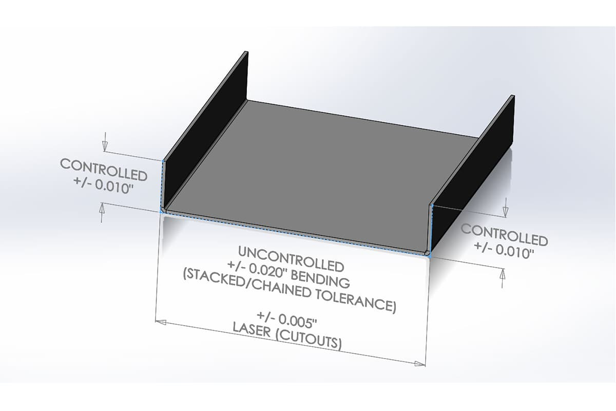
| Bend Angle | ±0.5° to ±1.0° | This is the hotspot for "tolerance stacking." The first bend may be spot-on, but even slight error becomes the reference for subsequent bends, letting deviations snowball. |
| Flange Length | ±0.2mm to ±0.5mm | Remember this rule of thumb: Minimum flange height ≈ 4 × material thickness + bend radius. Anything below this risks insufficient grip during bending, leading to slippage or deformation. |
| Bend Radius | Industry standard is typically 1 × material thickness | Too small a radius overstretches the outer fibers, risking cracks; too large increases springback, making angle control more difficult. |
(2) Key Factors and Insights
1) Material Springback – The No. 1 Nemesis of Bending Tolerances
This is the "memory effect" of sheet metal. When you bend it with force, it undergoes both plastic deformation (permanent) and elastic deformation (temporary). Once the bending force is released, the suppressed elastic deformation will partially “spring back,” causing the bend angle to open up. The higher the material’s strength and hardness, the more pronounced the springback. Modern press brakes use precise calculations to deliberately “overbend” (for example, aiming for 90°, they first bend to 88.5°) to accurately compensate for springback.
2) V-die Width – The balancing act of force and precision
The V-die opening width of the lower bending die is a strategic parameter that defines bending quality. The industry’s golden rule is: V-die width ≈ 6–8 times the material thickness. A die that’s too narrow is like trying to fold cardboard with a needlepoint—it demands enormous force and risks leaving deep marks in the material; a die that’s too wide will produce larger bend radii and make springback even harder to predict.
3) The hidden “fracture code”
During rolling, metal sheets develop microscopic textures known as grain direction. If your bend line runs parallel to the grain, it’s like splitting wood along the grain—micro-cracks can easily form on the outer bend surface. The ideal design is to position bend lines perpendicular to the material’s grain direction.

4.3 Stamping/Deep Drawing Tolerances: Balancing complex shapes
If laser cutting and bending are the artisanal craftwork of sheet metal, stamping and deep drawing are the miracles of industrial duplication. Using immense force, the die impresses its precise form into the sheet, making it ideal for high-volume production.
(1) Core control parameters
Forming depth, shape profile, and wall thickness uniformity.
(2) Key insight
In the stamping world, tolerances are born in the die. Once the die is finalized, it delivers extremely high dimensional consistency in mass production. This means the critical battle for controlling stamping tolerances happens early—during die design, manufacturing, and verification.
(3) Typical tolerances
Precision stamping can achieve dimensional tolerances of ±0.05 mm or tighter—levels seldom seen in other processes. However, for complex deep-drawn parts (such as a cup), the greatest challenge is maintaining consistent wall thickness, and tolerances may relax to ±0.1 mm or more.
(4) Influencing factors and key insights
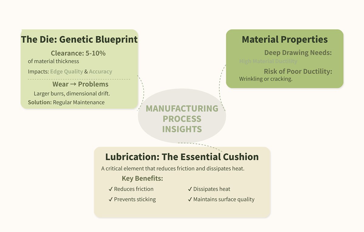
1) The die is the “genetic blueprint” of stamping
The clearance between the punch and die (typically 5–10% of material thickness) directly determines edge quality and dimensional accuracy. Over tens or hundreds of thousands of cycles, the die will inevitably wear—like a battle-worn hero—leading to larger burrs and dimensional drift. Regular die maintenance and lifespan management are critical to ensuring consistency in mass production.
2) Material ductility
Deep drawing is a process that flirts with the edge of material tearing. It heavily depends on the metal’s ductility; materials with poor elongation can’t withstand the intense deformation, making them prone to wrinkling or cracking.
Lubricating oil forms a microscopic film between die and material, acting as an invisible cushion that reduces friction, dissipates heat, and prevents sticking—an essential factor for maintaining surface quality and dimensional precision.
4.4 Assembly Tolerances: The ultimate test for welding and fastening
Assembly is the stage where all individual parts come together into the final product—and where the cumulative effect of all prior tolerances is judged. Even if each component is within spec, the accumulated tolerances can still cause the assembly to fail.
(1) Core control parameters
Post-weld thermal distortion, and position accuracy of locating features (such as press-fit fasteners).
(2) Practical rules and key insights
1) Heat is tolerance’s worst enemy
During welding, rapid localized heating (over 1,000°C) and subsequent cooling cause uneven expansion and contraction of the metal—this is the root cause of welding distortion. Such deformation is large-scale and unpredictable, easily erasing the millimeter-level accuracy achieved in earlier stages. The ISO 13920 standard defines general tolerance classes for welded structures, but controlling distortion is far more critical than simply meeting the standard.
2) The three pillars of controlling welding distortion: rigid fixtures
Use well-designed jigs to clamp workpieces rigidly during welding, suppressing any tendency to move. Optimize weld sequencing: Techniques like symmetrical welding or staggered welds act like the balance of a tai chi master—distributing internal stresses so that deformation trends counteract each other.
3) Reducing heat input
As long as full penetration is achieved, use fewer weld passes and lower current—like “slow simmering” instead of “flash frying”—to reduce total heat introduced.
Press-fit fastener (PEM®) positioning accuracy: The positional accuracy of such self-clinching fasteners depends entirely on the precision of their mounting holes, which are made in the first step—either by laser cutting or stamping. This perfectly illustrates sheet metal’s “butterfly effect”: an initial ±0.1 mm deviation will be faithfully carried through to final assembly.
4.5 Core Value Chart – Cross-process tolerance capability matrix
As a designer or engineer, quickly selecting the right process combination at the project’s outset—based on accuracy requirements, budget, and production volume—is a critical strategic decision. The chart below is your “battle map,” visually revealing the cost–benefit terrain of each option.
| Process | Key Advantages | Typical Dimensional Tolerance | Typical Angular Tolerance | Cost Range (per piece) | Suitable Volume |
|---|---|---|---|---|---|
| Laser Cutting | Extremely flexible, no tooling, handles complex profiles | ±0.1 mm ~ ±0.3 mm | N/A | Medium | Low to Medium |
| CNC Punching | Very fast for standard holes; highly efficient for specific forms | ±0.1 mm ~ ±0.2 mm | N/A | Medium-Low | Medium to High |
| Brake Forming | Core method for building 3D structures | ±0.2 mm ~ ±0.5 mm (flanges) | ±0.5° ~ ±1.0° | Medium | Low to High |
| Stamping/Deep Drawing | Ultimate in consistency and speed; extremely low cost | ±0.05 mm ~ ±0.2 mm (die dependent) | Formed in-die; high consistency | Low (very high die cost) | Very High |
| Welded Assembly | Permanent joining, adds structural strength | ±0.5 mm ~ ±2.0 mm (heat distortion is main factor) | ±1.0° ~ ±2.0° | High | Low to High |
V. How to Determine Sheet Metal Tolerances?
In the world of tolerances, there’s a hard-won rule proven by countless costly lessons: if a tolerance cannot be measured economically and reasonably, it has no business being on the drawing.
Typing a ±0.01 mm tolerance is just a few keystrokes for a designer; for the manufacturer, it may require a multi-million-dollar coordinate measuring machine (CMM) in a temperature-controlled lab. Inspection cost is the often-overlooked twin of tolerance cost—always present, yet rarely accounted for. Learning to choose a measurement tool that’s fit for purpose is the key to walking a graceful tightrope between quality and cost.
Quick Reference & Strategic Insights for Sheet Metal Inspection Tools
| Inspection Tool | Typical Accuracy | Best Use Case | Core Concept & Strategic Considerations |
|---|---|---|---|
| Vernier/Digital Calipers | ±0.02mm ~ ±0.05mm | Quick, everyday dimensional checks—measuring length, width, hole diameter, step depth, and other basic dimensions. The most common and efficient “foot soldier” on the production floor. | A pragmatic “good enough” approach. For loose tolerances of ±0.2mm or above, calipers deliver unmatched cost-effectiveness. Forcing them to verify ±0.05mm tolerances is like using a school ruler to measure a microchip—the measurement error may exceed the tolerance itself. |
| Protractor/Angle Gauge | ±0.5° ~ ±1.0° | Verifying bend angles. Rapidly checks if the bend is within tolerance. Digital angle gauges offer higher reading precision, making them the bend operator’s go-to tool. | The baseline for functional verification. This accuracy aligns with typical bending process tolerances. If your design demands tighter angular fits (e.g., ±0.25°), take it as a red flag—either revisit the design or prepare to pay extra for CMM or custom gauges. |
| Coordinate Measuring Machine (CMM) | ≤±0.005mm | The “final court of appeal” for intricate geometry and GD&T. Used for First Article Inspection (FAI), critical dimension sampling, and as the ultimate arbiter for positional accuracy, profile tolerances, and other complex GD&T requirements. | Exceptionally powerful yet extremely costly. CMM work is billed by the hour and requires complex programming. Specifying a tolerance that necessitates CMM verification is like pressing the “upgrade class” button for part cost. Summon this “judge” only when there is truly no alternative. |
| Optical Comparator/2D Vision System | ±0.01mm ~ ±0.02mm | The “eagle eye” for rapid 2D profile verification—ideal for inspecting complex outlines, small holes, and thin sheet parts. Magnifies the profile and overlays it directly with CAD data, far more efficient than a CMM. | The guardian of planar precision. For verifying laser-cut or stamped part outlines, it offers the perfect balance between accuracy and efficiency, allowing you to assess a complex part’s overall conformity in seconds. |
| Dedicated Gauges | Dependent on gauge precision | Consistency checking in high-volume production. For example, Go/No-Go gauges for hole diameters, or custom fixtures simulating assembly conditions—instant pass/fail decisions. | Built for ultimate efficiency. When production runs in the thousands, investing thousands (even tens of thousands) upfront in dedicated gauges is the smartest way to spread costs and cut inspection time to seconds per part. This “simple” method solves the most complex consistency challenges. |
Ⅵ. How to Perform Tolerance Analysis?
The methods of tolerance analysis are mainly one-dimensional and three-dimensional. The one-dimensional method does not need to buy software, so the cost is low, while the three-dimensional method costs more.
There are also two different methods for one-dimensional tolerance analysis, one is the worst case and the other is the root mean square method (RSS). The second method belongs to the category of statistical methods, while the limit method is relatively simple.
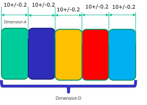
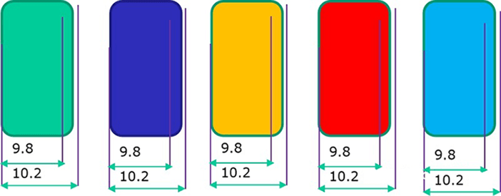
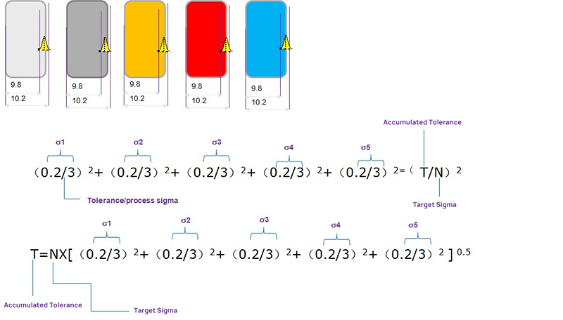
Upper dimension limit USL: 10.2+10.2+10.2+10.2+10.2=51
Lower dimension limit: 9.8+9.8+9.8+9.8+9.8=49, so the fluctuation range of dimension D is 49~51

The limit method is the direct accumulation of each size boundary, while the statistical method is to consider the probability of each size to calculate the probability of each size after accumulation.
If we want to use the probability method to analyze, we need to know the respective probability of each dimension. The following is the distribution probability of dimension A. If it is a stable process, then it should be a normal distribution.
Then we need to know the overall distribution, and we need to know the two parameters of the normal distribution, the mean and the standard deviation.
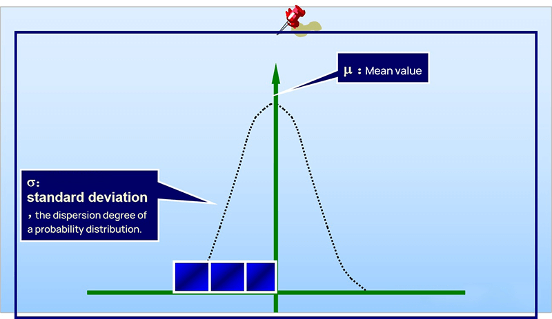
The standard deviation describes the discrete state of a distribution. It is a measure of the average dispersion of a group of data.
The standard deviation is large, indicating that there is a large difference between most values and the average value. The small standard deviation indicates that the difference between most values and the average is small.
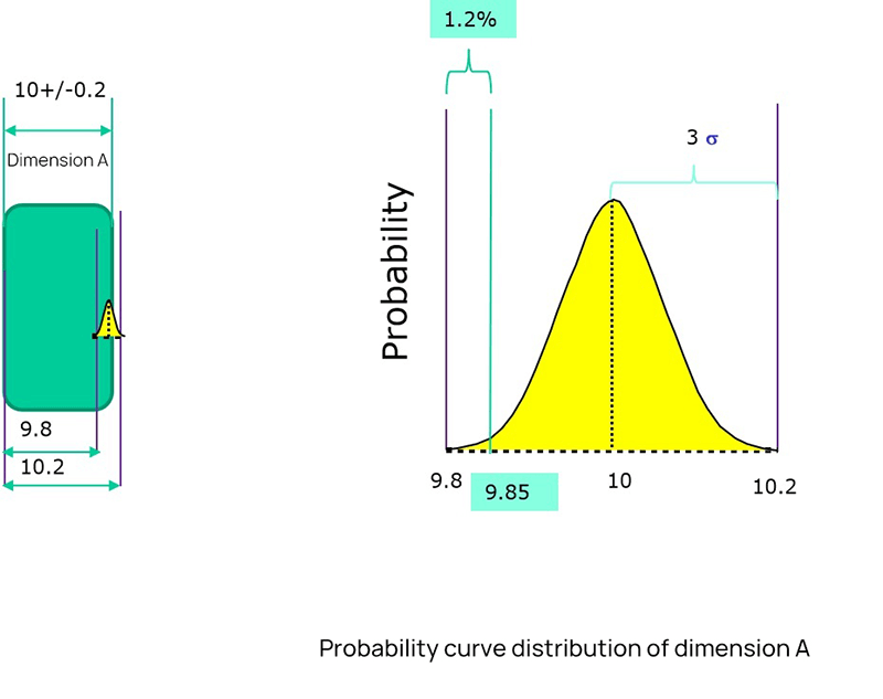
After knowing the mean value and standard deviation, we can see the distribution of this dimension.
As shown in the figure above, the mean value is 10 and the standard deviation is 0.067.
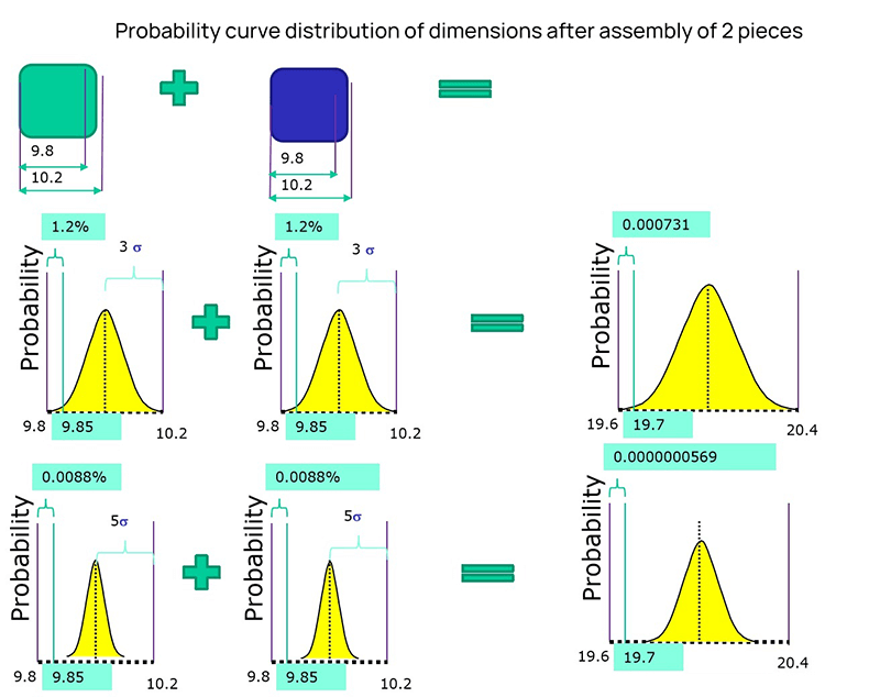
If two dimensions are accumulated, the mean value is the same, and the standard deviation is different, then the cumulative distribution is completely different. The results will be different if the distribution state of dimension fluctuation is different.
The original definition of tolerance is the way of limit definition, which can not describe a distribution well. Two parameters are required to describe a distribution, mean value and standard deviation.
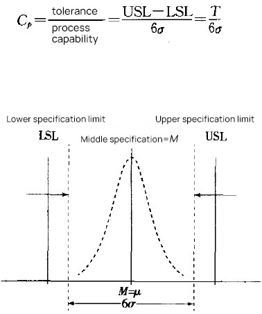
In order to associate with the original interval tolerance, another parameter - CPK needs to be introduced. To simplify the description, we assume that the center does not shift, CP=CPK.
As shown in the figure below, with a tolerance range and CP, you can know the standard deviation. Add the mean value and the normal distribution can be determined.
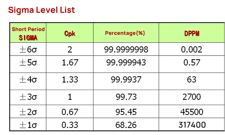
The following table shows the sigma level corresponding to CP (CPK). CP (CPK) 2 means 6 sigmas, and CP (CPK) 1.67 means 5 sigmas. When we know CP (CPK), we can get the sigma level, and we know the normal distribution.
Therefore, the mean value, tolerance range, and CP (CPK) should be known during tolerance analysis.
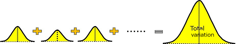
If we know the distribution of all dimensions in the dimension chain, we need to calculate the distribution of the total variation.
We need the calculation formula of RSS(Root Sum Square), that is, the square of the standard deviation of the normal distribution of the overall standard deviation is equal to the square sum of the standard deviation of each sub-distribution.
Therefore, the standard deviation of each dimension=the sigma level corresponding to the tolerance/CP, as shown in the figure below σ expresses the standard deviation.
σ²= (tolerance/process sigma) ²
Stacking different σ² is the total distribution of the overall standard deviation σ²
Finally, an excel template can be used to implement the analysis process. Fill the relevant parameters of each dimension into the table in the template to get the stacking results of the overall standard deviation.
For more details on how our equipment helps maintain these precise standards, you can download our product Brochures.
Ⅶ. Industry Standards and Specifications
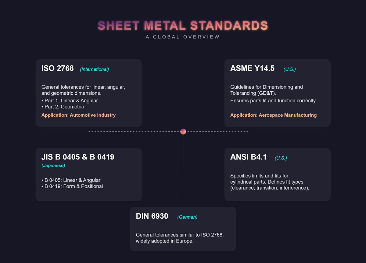
7.1 ISO 2768
ISO 2768 is a widely used international standard for general tolerances in precision sheet metal manufacturing. It covers linear dimensions, angular dimensions, and geometric tolerances. The standard is divided into two parts:
- ISO 2768-1: General tolerances for linear and angular dimensions without individual tolerance notation.
- ISO 2768-2: General tolerances for geometric features without individual tolerance notation.
7.2 ASME Y14.5
ASME Y14.5 is a U.S. standard providing guidelines for dimensioning and tolerancing. It is essential for ensuring that parts fit together properly and function as intended. It includes:
- Geometric Dimensioning and Tolerancing (GD&T): A system for defining and communicating engineering tolerances.
- Symbols and Notations: Standardized symbols for representing tolerances on engineering drawings.
7.3 ANSI B4.1
ANSI B4.1 is another U.S. standard specifying preferred limits and fits for cylindrical parts. It provides guidance on:
- Tolerance Grades: Different levels of precision based on functional requirements.
- Fits: Types of part fits, such as clearance, transition, or interference fits.
7.4 DIN 6930
DIN 6930 is a German standard specifying general tolerances for linear and angular dimensions in mechanical engineering. It is similar to ISO 2768 and is widely adopted across Europe.
7.5 JIS B 0405 and JIS B 0419
These Japanese standards provide guidelines for general tolerances in sheet metal manufacturing:
- JIS B 0405: General tolerances for linear and angular dimensions.
- JIS B 0419: General tolerances for form and positional accuracy.
7.6 Practical Applications of Standards
Including practical examples of how these standards are used can help illustrate their relevance. For instance:
- ISO 2768: Applied in the automotive industry to ensure parts from different suppliers fit seamlessly together.
- ASME Y14.5: Used in aerospace manufacturing to maintain high precision and reliability in sheet metal components.
7.7 Example Tolerance Table Based on ISO 2768
| Dimension Range (mm) | Tolerance Class (f) – Fine | Tolerance Class (m) – Medium | Tolerance Class (c) – Coarse |
|---|---|---|---|
| 0.5 - 3 | ±0.05 | ±0.1 | ±0.2 |
| 3 - 6 | ±0.05 | ±0.1 | ±0.3 |
| 6 - 30 | ±0.1 | ±0.2 | ±0.5 |
| 30 - 120 | ±0.15 | ±0.3 | ±0.8 |
| 120 - 400 | ±0.2 | ±0.5 | ±1.2 |
7.8 Examples of Geometric Tolerances Based on ASME Y14.5
| Feature Control Frame | Description |
|---|---|
| Position Tolerance | Controls the positional accuracy of a hole |
| Flatness Tolerance | Ensures surface flatness within specified limits |
| Perpendicularity Tolerance | Controls perpendicularity to ensure correct bend angles |
Ⅷ. Conclusion
This article has outlined the fundamentals of sheet metal tolerancing, methods for tolerance analysis, and key industry standards and specifications. As part designs grow more complex, the demand for tighter and more precise tolerances continues to increase.
Sheet metal fabrication involves processes such as punching, cutting, stamping, and bending to transform metal sheets into finished components. To meet the tolerances required by sheet metal design guidelines, manufacturers must utilize precision machinery throughout production.
With 20 years of extensive experience in sheet metal fabrication equipment, ADH offers advanced solutions, including Swing Beam Shearing Machine and Single Table Fiber Laser Cutting Machine.
If you are considering purchasing sheet metal processing equipment, our product specialists can provide you with detailed information. We invite you to contact us to discuss your specific requirements.
IX. FAQs
1. Why are tolerances important in sheet metal fabrication?
Tolerances are crucial in sheet metal fabrication because they ensure parts are interchangeable and fit together properly, meet performance requirements, and balance precision with manufacturing costs. By accounting for variability in manufacturing processes and material properties, tolerances maintain the desired functionality and quality of parts.
Adhering to industry standards, such as ISO 2768, helps ensure consistency and quality across different manufacturers. Practical tolerances should be as loose as necessary to ensure functionality while avoiding unnecessary costs associated with overly tight tolerances.
2. What is the difference between dimensional and geometrical tolerances?
Dimensional tolerances refer to the permissible variations in the physical size of a sheet metal part, ensuring that its dimensions fall within a specified range for proper fit and alignment. In contrast, geometric tolerances are more complex and address the shape, position, and orientation of features relative to each other, encompassing aspects like form, orientation, and location.
While dimensional tolerances focus on size, geometric tolerances ensure precise alignment and functionality in complex assemblies. Understanding these differences is crucial for achieving the desired quality and performance in sheet metal fabrication, as each type serves distinct purposes.
3. How can quality control methods help in maintaining precision in sheet metal manufacturing?
Quality control methods maintain precision in sheet metal manufacturing by establishing clear quality standards, ensuring material quality, and implementing process mapping and inspection protocols. Advanced technologies like CAD/CAM and CNC machines enhance precision, while regular calibration and standardization of tools ensure measurement accuracy.
Tolerance management, aligned with industry standards like ISO 2768, is crucial for handling different material requirements. Regular reviews, data analytics, and IoT integration allow real-time monitoring, reducing defects and promoting continuous improvement. These practices ensure high precision, consistency, and reliability throughout the manufacturing process.


