I. Introduction
Laser cutting technology, as an advanced thermal processing method, has become an indispensable core forming solution in modern manufacturing thanks to its exceptional precision, high production efficiency, and outstanding adaptability. It plays a pivotal role in a wide range of industries, including automotive manufacturing, aerospace, precision electronics, and high-end equipment production.
But what exactly is the physical mechanism behind laser cutting? What are the essential functional modules that make up a complete laser cutting system? How is the entire process—from digital design to finished components—managed with such accuracy? And how does laser cutting compare to traditional mechanical or plasma cutting methods in terms of advantages and areas of application?
This article will systematically address these questions by providing a comprehensive explanation of the fundamentals of laser cutting, the structure of its equipment, the control of process parameters, and the unique application features of various materials across different industries. It aims to serve as an authoritative and detailed technical reference for engineers, technical managers, and decision-makers.
II. Overview of Laser Cutting Machines
1. Principle of Laser Cutting Machines
The principle behind laser cutting machines lies in using a high-energy-density laser beam to heat, melt, or vaporize materials along a precisely controlled cutting path, enabling clean and accurate separation.
(1) Laser Generation
At the heart of every laser cutting machine is the laser generator. It produces a highly focused, high-energy laser beam using a specific medium—such as CO₂ lasers, fiber lasers, or solid-state lasers. Laser generation relies on an external pump source (like electrical current or gas) to excite the active medium, causing it to emit coherent photons and form a laser beam.
(2) Laser Focusing
Once generated, the laser beam is focused through an optical system featuring lenses, mirrors, and other components. The purpose of focusing is to condense the laser into a tiny spot, creating a high power density heat source on the material’s surface. This process is typically managed by optical elements within the cutting head.
(3) Cutting Process
The concentrated laser beam is directed onto the material’s surface. Thanks to its high energy density, the material rapidly heats up to its melting or boiling point, and may even vaporize. The laser interacts differently with various materials:
- For low melting point materials (like plastics), the laser melts the material to create a cut.
- For high melting point materials (such as metals), the laser vaporizes the material directly, producing a narrow slit.
- In some cases, the laser may also induce chemical reactions in the material, such as oxidation or combustion.

(4) Gas Assistance
During cutting, an assist gas (such as nitrogen or oxygen) is commonly sprayed onto the cutting area. This helps expel the molten or vaporized material, cools the cutting zone, and prevents burrs or slag from forming. The use of assist gas is crucial for enhancing both the quality and efficiency of the cut.
(5) Path Control
Laser cutting machines are typically operated by computer numerical control (CNC) systems, which guide the laser beam along predetermined shapes and paths with great precision. By adjusting parameters such as cutting speed, laser power, and focal length, operators can control the width, taper, and quality of the cut.
2. Main Types of Laser Cutting Machines
| Category | Type | Description |
| By Laser Type | Fiber Laser Cutting Machine | Uses fiber doped with rare earth elements (e.g., Ytterbium) as the gain medium, generating laser via semiconductor pumping. |
| CO2 Laser Cutting Machine | Uses a carbon dioxide gas mixture as the working medium, generating laser through gas discharge. | |
| YAG/Disk Laser | Utilizes Nd:YAG crystal or disk as the medium, generating laser via lamp pumping or semiconductor pumping. | |
| UV/Green Laser Cutting Machine | Generates short-wavelength ultraviolet light (355nm) or green light (532nm) via crystal frequency doubling. | |
| By Processing Material | Metal Laser Cutting Machine | Mainly uses fiber lasers, suitable for various metal sheets/pipes. |
| Non-Metal Laser Cutting Machine | Commonly uses CO₂ lasers, suitable for cutting wood, acrylic, fabrics, etc. | |
| Composite Material Laser Cutting Machine | Requires special wavelengths (e.g., UV) to process carbon fiber, ceramic-based composites, etc. | |
| By Mechanical Structure | Gantry Laser Cutting Machine | Features a moving beam and fixed worktable, offering high rigidity for processing large-format sheets. |
| Cantilever Laser Cutting Machine | Laser head is suspended on a single arm, occupying less space, suitable for pipes or small-sized workpieces. | |
| Robotic Arm Laser Cutting Machine | Equipped with a six-axis mechanical arm carrying the laser head, offering flexible processing of 3D surfaces, such as automotive parts. |
Ⅲ. Core Components of a Laser Cutting Machine
1. Laser Source
The laser generator is the heart of a laser cutting machine, responsible for producing the laser beam. Common types of lasers include:
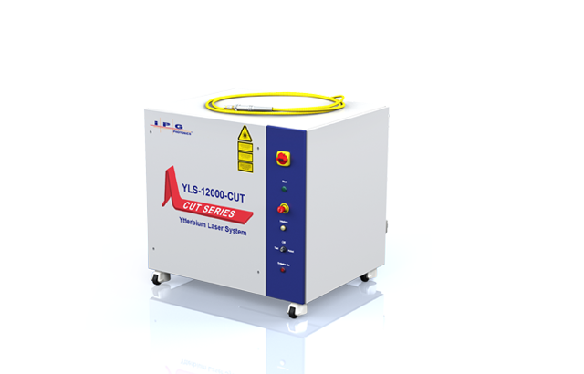
(1) Fiber Laser
A fiber laser injects energy into a fiber doped with rare-earth elements through a pump source. Using the principles of population inversion and stimulated emission within an optical resonator, it amplifies photons to generate a high-power, highly directional laser beam.
This is the mainstream technology in metal processing today. With a wavelength of approximately 1.06 micrometers, it is particularly well-suited for cutting various metals, including carbon steel, stainless steel, aluminum, and copper.
(2) CO2 Laser
A CO2 laser excites a gas mixture electrically, utilizing population inversion and stimulated emission to amplify photons within a resonator, ultimately producing a powerful, highly focused laser beam.
With a wavelength of about 10.6 micrometers, this mature technology still holds a significant position in the field of non-metal cutting.
(3) YAG Laser
YAG lasers use a crystal of yttrium aluminum garnet doped with neodymium ions to generate laser light when energized by a pump source.
Operating at a wavelength of about 1.06 micrometers, YAG lasers are suitable for cutting thick metal materials, though they tend to have higher costs and shorter lifespans.
Other types, such as semiconductor and liquid lasers, are primarily used in medical and scientific research, with limited industrial applications.
For more detailed technical information or product details, please visit our Brochures.

2. Cutting Head
The cutting head serves as the laser cutting machine’s execution unit, focusing the laser beam onto the material for cutting. It typically comprises a nozzle, focusing lens, capacitive sensor, and auxiliary gas nozzle, and is controlled by a servo or stepper motor to achieve precise Z-axis movement.
(1) Collimating/Focusing Lens
These optical lens systems adjust and focus the laser beam to achieve the desired spot size.
(2) Capacitive Sensor
This sensor continuously monitors the distance between the nozzle and the workpiece surface, ensuring a constant focal position—an essential factor for maintaining cutting quality, especially when processing uneven sheets.
(3) Nozzle
Located at the bottom of the cutting head, the nozzle directs high-pressure auxiliary gases (such as oxygen, nitrogen, or air) coaxially toward the cutting point. Its shape, aperture size, and distance from the workpiece (nozzle height) are critical to cutting quality, affecting edge roughness, slag formation, and dross.

(4) Protective Lens
The protective lens shields the expensive internal focusing and collimating lenses from contamination by slag and spatter generated during cutting.
3. Motion Control System
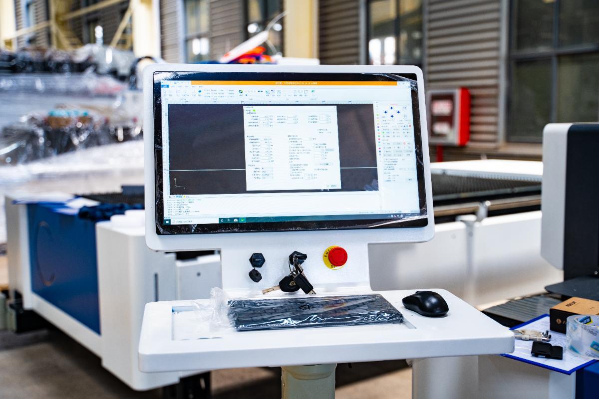
(1) Motion Controller (CNC System)
The motion controller is the core of the laser cutting machine’s motion control system. It reads cutting program files (such as G-code), retrieves cutting parameters, and generates control commands to precisely manage the movements of the laser head and worktable.
Advanced controllers support multi-axis synchronized control (such as X, Y, and Z axes) and connect to multiple servo drives and motors via high-speed communication buses (e.g., EtherCAT), enabling high-precision cutting along complex paths.
Additionally, the controller manages the laser’s power and frequency through communication modules to ensure optimal cutting quality.
(2) Motor
The motors in a laser cutting machine drive the movement of the laser head, with the main types including:
| Motor Type | Features | Applicable Scenarios |
| Stepper Motor | Fast start-up speed, sensitive response, suitable for applications that do not require high cutting accuracy. | Low-end or entry-level laser cutting machines, industries and products with lower cutting requirements. |
| Relatively low price. | ||
| Servo Motor | High mobility, smooth movement, strong load capacity, stable performance. | Industries with high requirements for cutting accuracy and speed, such as metal processing. |
| Can achieve high-speed and smooth movement of the laser head, smooth cutting edges, and fast cutting speed. | ||
| Supports intelligent management, can automatically adjust parameters, and improve operational stability and efficiency. | ||
| Linear Motor | Directly drives the laser cutting head to move linearly, eliminating the intermediate links of traditional mechanical transmission. | High-precision, high-speed cutting needs, especially widely used in fiber laser cutting machines. |
| High acceleration, high speed, high positioning accuracy. |
1_w1200-1.jpg)
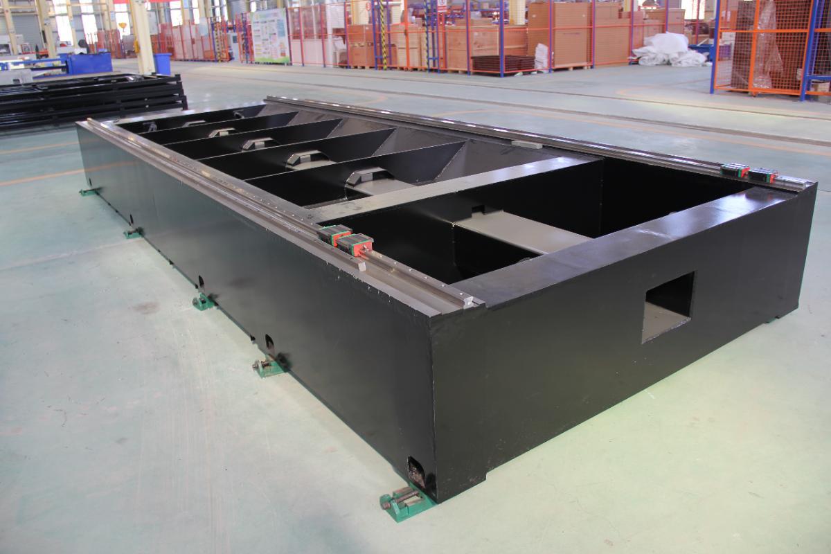
(3) Machine Tool (Worktable)
The machine tool forms the mechanical foundation of the laser cutting machine, responsible for supporting and securing materials to be cut, and executing precise X, Y, and Z-axis movements according to CNC system instructions. The stability of the machine tool directly impacts cutting quality, making high-precision and high-stability machine tools an essential component of laser cutting equipment.
Common types of machine tools include:
1)Gantry Laser Cutting Machine
Featuring a gantry structure, the cutting area is fully enclosed and equipped with lighting. This design provides excellent rigidity and high precision, making it suitable for large-format cutting tasks.
2)Cantilever Laser Cutting Machine
With an open structure, this machine allows for easy loading and unloading of materials. It is ideal for cutting standard-sized sheet materials, offering flexibility and suitability for small to medium-sized workpieces.
3)Frame Laser Cutting Machine
The laser is mounted on a frame and moves with it, ensuring a constant optical path. This type is designed for heavy-duty industries such as construction machinery, shipbuilding, and locomotive manufacturing.
4)Tabletop Laser Cutting Machine
Compact in design, this machine excels at processing thin sheets, making it widely used in industries like elevator manufacturing and electrical switchgear production.
5)Robotic Arm Laser Cutting Machine
Equipped with automated operation capabilities, this machine can cut workpieces with complex shapes.
4. Auxiliary Systems
Auxiliary systems include gas lines, air supply systems, and dust removal systems, which provide necessary cutting gases (such as nitrogen and oxygen) and collect dust and debris generated during the cutting process. These systems ensure the safety and environmental compliance of the cutting operation.
(1) Auxiliary Gas Supply System
Modern laser cutting machines integrate the auxiliary gas supply system with the CNC system, enabling automatic regulation of gas flow and pressure to optimize cutting processes. High-pressure gas nozzles deliver the auxiliary gas precisely to the cutting point, removing molten material, keeping the cutting area clean, cooling the material, and preventing deformation. Different gases are used to achieve specific cutting effects depending on the application.
| Gas Type | Function and Characteristics | Applicable Materials and Effects |
|---|---|---|
| Nitrogen (N₂) | Inert gas, prevents oxidation, ensures bright and colorless cut edges, suitable for high-quality cutting. Reduces costs and increases cutting speed and productivity. | Stainless steel, aluminum, and other materials requiring high-quality cutting. |
| Oxygen (O₂) | Highly reactive gas, supports combustion to generate an exothermic reaction, increasing cutting speed and efficiency, but may cause cut edge oxidation and a carbonized layer, affecting surface quality. | Carbon steel and thicker materials, suitable for applications not sensitive to cut edge oxidation. |
| Compressed Air | Economical, contains approximately 21% oxygen, cutting speed and efficiency are between nitrogen and oxygen, cut edges may have oxidation and burrs, suitable for parts where cut edge color is not critical. | General metal cutting, suitable for products with subsequent deburring processes. |
(2) Cooling System
During operation, laser cutting machines generate a significant amount of heat, especially those equipped with high-power lasers. If this heat is not dissipated promptly, it can lead to equipment overheating, which may damage the laser, optical components, and other critical parts.
As a result, the cooling system plays an essential role in laser cutting machines. It not only prevents the equipment from overheating but also ensures the laser operates within its optimal temperature range, thereby enhancing both cutting efficiency and precision.

Cooling systems generally fall into two main categories: air cooling and water cooling. Air cooling relies on fans to force air circulation, removing heat from the laser’s heat sink or radiator. While it is cost-effective, its cooling capacity is limited, making it suitable primarily for low-power laser cutting machines.
Water cooling systems have much stronger heat dissipation capabilities and are essential for high-power laser machines, typically consisting of the following components:
| Component | Function |
|---|---|
| Chiller | Core component of the water cooling system, responsible for heating cooling water and releasing heat to the external environment through a heat exchanger. |
| Cooling Water Circulation Pipeline | Transports cooling water to key components such as lasers and optical elements, removes heat, and returns to the chiller for circulation. |
| Radiator | Releases heat from the cooling water into the external environment, typically installed outside the chiller or laser cutting machine. |
| Water Tank and Filter | Stores cooling water and filters impurities in the water to prevent radiator blockage. |
| Temperature Sensor | Monitors the temperature of the laser and feeds temperature signals back to the control system to adjust the cooling system's operating state. |
(3) Smoke Extraction and Dust Removal System
During the cutting process, laser cutting machines generate a significant amount of smoke, dust, and harmful gases. These pollutants not only pose health risks to operators but can also corrode and damage equipment. Therefore, the dust removal and smoke extraction system operates based on three main principles: smoke collection, smoke purification, and smoke emission.
Smoke collection utilizes a dust hood to channel fumes and dust generated during cutting into pipelines. For example, a blower fan directs the smoke through a grated ventilation duct toward a mobile suction unit, where it is drawn in and transported to the dust collector.
Smoke purification occurs once the captured fumes enter the dust collector, passing through a multi-stage filtration system—such as high-efficiency filters and dust collectors—to remove particles of varying sizes. Exhaust and dust removal systems typically utilize multiple filtration materials to trap different particle sizes, ensuring that the workshop air quality complies with environmental standards.
Smoke emission refers to the process where purified air is expelled outdoors via exhaust devices, maintaining fresh air within the workshop.

(4) Safety Protection System
The safety protection system is comprised of the following four core components:
1)Protective Covers and Shields: Laser cutting machines are typically equipped with transparent or semi-transparent shields to protect operators from direct laser radiation and to block flying metal debris and fumes.
2)Sealed Protective Enclosure System: Modern laser cutting machines use enclosed protection systems, forming fully or partially sealed chambers to prevent laser leakage and the spread of harmful fumes, while allowing for direct loading and unloading of workpieces. This design improves operational efficiency and reduces safety risks.
3)Safety Interlock Switches: Protective and sealed covers are usually fitted with interlock switches, ensuring that the laser cutting machine can only be activated when all safety devices are correctly in place, thus preventing laser leakage accidents caused by improperly closed covers.
4)Emergency Stop Button: The machine is equipped with emergency stop buttons. When pressed, the laser and power supply are immediately shut off to prevent the escalation of accidents and to ensure operator safety.

For more detailed information on laser cutting machine safety, please refer to Laser Cutting Machine Side Effects.
IV. Main Cutting Methods
1. Vaporization Cutting
A focused laser beam rapidly heats the material's surface to its boiling point, causing immediate vaporization and the formation of a "pinhole." The expanding vapor then erodes the molten walls of the cut, ejecting material and gradually deepening and widening the hole.
This method is mainly used for cutting non-metallic materials or extremely thin metals, such as plastics, wood, and paper, with a relatively high material loss during the process.
2. Melt Cutting
The laser beam heats the material to its melting point, while a high-pressure assist gas jet is directed at the cutting zone to blow the molten material out of the kerf. Removing the molten material in this way prevents re-solidification and significantly reduces the power required to continue cutting.
This method is primarily used for precise cutting of stainless steel, aluminum alloys, titanium alloys, and other reactive metals, as well as non-metals like acrylic and plastics. It is the most common method for cutting stainless steel and aluminum.

3. Thermal Stress Cracking
This technique takes advantage of the sensitivity of brittle materials to thermal fracture. The laser beam is focused on the material surface, causing localized heating and subsequent thermal expansion. This differential expansion generates internal stresses, leading to crack formation. By precisely moving the laser beam, cracks can be guided along the desired cutting path at speeds of several meters per second.
This technology is mainly utilized for cutting brittle materials such as glass.
Ⅴ. Laser Cutting Operation Process
1. Design and Programming: The Starting Point of Digital Work
Before the laser is powered on, every cutting task begins in the digital realm. The objective at this stage is to create precise part geometries and translate them into instructions that the machine tool can understand.
(1) Designing Parts with CAD Software
Everything starts with Computer-Aided Design (CAD). Engineers or designers use software such as AutoCAD, SolidWorks, or Adobe Illustrator to draft the two-dimensional (2D) outlines of components.
The completed designs are typically saved as DXF or DWG files—industry-standard formats for exchanging 2D geometric data.
(2) Generating Toolpaths and G-Code with CAM Software
Once the CAD files are ready, the next step is programming with CAM software like Lantek or SigmaNEST. CAM software handles several critical tasks:
1) Path Planning: Automatically or manually plans the movement path of the laser head, including the cutting sequence and the placement of lead-in and lead-out points, to prevent flaws at the start and end of part contours.
2) Nesting: Intelligently arranges multiple part outlines on a single sheet to maximize material utilization and minimize waste.
3) Parameter Association: Assigns the appropriate cutting parameters to different contours. Ultimately, the CAM software generates G-code—a numerical control language that precisely details the laser head’s coordinates along the X, Y, and Z axes, laser on/off commands, power levels, and auxiliary gas control. This G-code file serves as the final blueprint that drives the laser cutting machine.

2. Equipment Preparation and Parameter Setup: Precision Tuning in the Physical World
Once the digital blueprint is ready, operators must meticulously configure the laser cutting machine. The quality of these preparations directly impacts the final cutting results.
(1) Material Placement and Securing
The metal sheet to be processed is carefully positioned on the machine’s worktable. It is essential that the sheet is perfectly flat and free of warping, as any height variation can affect the focal distance and result in inconsistent cut quality. The sheet is firmly secured using clamps or the machine’s vacuum suction system to prevent movement during high-speed cutting.
(2) Nozzle Height and Focal Distance Calibration
1) Nozzle Height
This is the distance from the tip of the nozzle to the material’s surface, which influences the stability and efficiency of the auxiliary gas flow. Modern machines are typically equipped with capacitive sensors that automatically maintain a constant nozzle height.
2) Focal Distance
This refers to the position of the laser beam’s focal point relative to the material’s surface. The focal point can be set on, above, or below the surface, resulting in different cutting effects. For example, when cutting carbon steel, the focal point is often set at one-third of the sheet’s thickness; for stainless steel, it may be set at the surface. The correct focal distance is key to achieving narrow kerfs, smooth cut edges, and minimal dross.
(3) Setting Cutting Speed, Power, Gas Type, and Pressure
This is the “core of the process” in laser cutting. Operators adjust or recall preset parameters in the machine control system based on the material type (such as carbon steel, stainless steel, or aluminum alloys) and thickness.
1) Cutting Speed
Working in tandem with power, speed determines the amount of energy delivered to the material. If the speed is too high, the cut may not penetrate; if too slow, it can lead to excessive melting, rough edges, and increased dross.
2) Laser Power
Should be sufficient to melt or vaporize the material, but not so high as to waste energy or cause an overly large heat-affected zone (HAZ).
3) Gas Type and Pressure
| Gas Type | Main Application | Characteristics | Advantages | Disadvantages |
|---|---|---|---|---|
| Oxygen (O₂) | Mainly for carbon steel | Reacts exothermically with molten metal, increasing cutting speed, but slight oxidation on edge | High cutting speed | Slight oxidation on the cut edge |
| Nitrogen (N₂) | Mainly for stainless steel and aluminum alloys | Acts as a shielding gas to prevent edge oxidation, creating a bright, clean cut surface, but requires higher laser power | No oxidation on the cut, bright and clean edge | Requires higher laser power, higher operating cost |
| Air | For low-cost cutting of thin materials | Low cost, can substitute nitrogen, but results in lower cut quality | Low cost | Cut quality not as good as nitrogen |
| Gas Pressure | For all cutting processes | Sufficient pressure effectively blows molten material out from the cut bottom, improving cut quality and efficiency | Enhances cutting efficiency and quality | Insufficient pressure can lead to cutting defects |
3. Processing Execution and Real-Time Monitoring: Integrating Automation with Manual Supervision
(1) Initiating the Machining Program
Before actual cutting begins, a dry run is typically performed—this means the laser head follows the programmed G-code path without activating the laser. This step helps verify that the path is correct and checks for any potential collision risks. Once everything is confirmed, the operator dons safety goggles, closes the protective doors, and officially launches the machining program.
(2) Real-Time Monitoring via Sensors
Throughout the cutting process, both the operator and the machine system monitor the operation simultaneously:
1) Visual Monitoring
Operators observe the color, shape, and height of the cutting sparks. For instance, when cutting carbon steel under optimal conditions, the sparks should spread downward evenly. Abnormal spark patterns may indicate improper cutting parameters or a clogged nozzle.
2) Sensor-Based Monitoring
Advanced machines are equipped with various sensors that continuously monitor beam alignment, focus stability, nozzle condition, and laser power. If the system detects a failure in cutting through the material or a drop in cut quality, it can automatically pause the process, issue an alert, and even attempt to adjust parameters automatically to restore normal cutting.
4. Finished Product Inspection and Post-Processing
Once cutting is complete, the parts removed from the worktable are not yet finished products. They must undergo inspection and any necessary post-processing before moving on to the next production phase or being delivered to the customer.
(1) Deburring, Cleaning, and Surface Treatment
Thermal cutting often leaves a small amount of solidified slag or burrs along the lower edges of the parts. Depending on the required precision and subsequent application, these can be removed using manual grinding, deburring machines, or tumbler polishing.
After cutting, any oil or dust on the part's surface should be cleaned. Depending on requirements, additional surface treatments such as sandblasting, painting, electroplating, or anodizing may be applied.
(2) Inspection Methods and Tolerance Verification
Quality control is the final and most critical stage. Inspectors use a variety of tools and techniques to ensure that each part meets the specifications of the design drawings.
1) Visual Inspection: Checks for surface finish, the presence of slag or burrs, and defects such as burn marks.
2) Dimensional Measurement: Key dimensions—such as hole diameter, length, and width—are measured using calipers, micrometers, and similar tools.
3) Tolerance Verification: For high-precision parts, coordinate measuring machines (CMM), vision measurement machines (VMM), or 3D laser scanners may be used to verify that geometric dimensions and positioning are within the tolerances specified in the drawings. Only parts that pass inspection are cleared for the next stage.
Ⅵ. Applications and Materials Suitable for Laser Cutting
1. Applicable Materials
Laser cutting technology is suitable for both metallic and non-metallic materials:
Metal materials include steel, stainless steel, aluminum alloys, brass, copper, titanium alloys, precious metals, and more, typically cut using fiber laser cutting machines.
Non-metal materials encompass plastics (such as acrylic, nylon, polypropylene, polyethylene, etc.), wood (softwood, hardwood, plywood, MDF), leather, textiles, rubber, paper, foam, acrylic glass, and others. These are best processed with CO2 laser cutting machines.
The versatility of laser cutting allows it to process not only flat sheet materials but also pipes and irregular-shaped components. For equipment that supports both sheet and tube processing, refer to the Dual-use Fiber Laser Cutting Machine.
The following table provides a reference for the types of laser cutting machines suitable for different materials:
| Material Category | Typical Materials | Recommended Laser | Key Considerations |
|---|---|---|---|
| Metals | Carbon steel, stainless steel | Fiber laser | Use appropriate assist gas (O₂ or N₂) |
| Reflective Metals | Aluminum, copper, brass | High-power fiber laser | High reflectivity; requires anti-reflection technology and high power |
| Non-metals | Acrylic, wood, leather | CO₂ laser | Smooth edges for acrylic; strong airflow assistance needed for wood edges |
| Not Suitable | Polyvinyl chloride, halogenated plastics | Prohibited | Releases toxic and corrosive gases, harmful to humans and equipment |
2. Industry Applications
Laser cutting technology has made significant inroads across a variety of industries, with its main applications including:
(1) Automotive Manufacturing
Laser cutting is used for high-precision cutting of body structures, interior components, engine parts, exhaust systems, and suspension systems. It meets the demands of complex designs and strict safety standards, serving as an alternative to traditional stamping processes.
(2) Construction and Structural Manufacturing
Laser cutting is applied in the fabrication of large structural components such as bridges, tunnels, connecting plates, and bases. It ensures precision and efficiency, making it suitable for materials like steel structures and wood.
(3) Electronics Industry
Laser cutting is utilized for circuit boards, electronic component casings, connectors, heat sinks, and more. It guarantees micron-level accuracy and enables the processing of intricate patterns, while also being used for marking and engraving electronic products.
(4) Medical Industry
Laser cutting is essential in manufacturing medical devices and implants—such as cardiac stents, orthopedic implants, and surgical instruments—offering micron-level precision with minimal thermal impact to ensure material biocompatibility and product quality.
(5) Shipbuilding and Heavy Machinery
Laser cutting is employed for precision cutting of marine steel plates and metal tubing for heavy equipment, ensuring high-quality edges and reducing the need for subsequent processing.
(6) Textile and Fashion Industry
Laser cutting is used for intricate designs and customized cuts in garment fabrics, supporting the production of high-end fashion and functional apparel.
(7) Advertising and Decoration Industry
Laser cutting enables the engraving and cutting of intricate patterns, enhancing product aesthetics and personalization.
For a more comprehensive look at industry applications, visit Laser Cutting Machine Uses.

Ⅶ. Conclusion
Laser cutting technology is a highly integrated modern manufacturing method, blending optical physics, precision engineering, and computer numerical control. Its fundamental principle lies in harnessing a high-energy laser beam, which is precisely focused onto the material’s surface through an advanced optical system. The CNC system then transforms digital design files into actual cutting paths with exceptional accuracy.
The outstanding performance of a laser cutting machine depends on the seamless coordination of its core components: the laser source generates a high-quality beam, the transmission and focusing system ensures accurate energy delivery, the motion control system provides precise operation, and various auxiliary systems maintain stable and continuous operation.
In summary, a laser cutting machine is not merely a piece of equipment, but a cutting-edge technology bridging the digital and physical worlds. Thanks to its exceptional precision, flexibility, and high degree of automation, it has become an indispensable tool in modern manufacturing, driving technological advancement and innovation across industries such as automotive, aerospace, electronics, and healthcare, and transforming the realization of complex designs into an efficient and practical reality. If you are ready to leverage this power for your projects, please contact us to discuss your specific needs with our experts.