I. Strategic Introduction
In the intricate game of modern manufacturing, a company's competitiveness lies not only in grand strategic layouts but also deep in every minute detail of the production line. Sheet metal bending, seemingly a routine process, hinges on its calculation accuracy—especially in the determination of flat pattern lengths. Even millimeter-level errors, or smaller, can silently erode profits, derail projects, and destabilize the company’s footing in the market. This chapter, from a strategic vantage point, examines why precision in bending calculations down to the millimeter is vital to a company’s survival.
1.1 The Hidden Cost of Inaccuracy
When bending calculations are off, the consequences are far from "close enough" or "slightly flawed." Such small inaccuracies quickly accumulate into a complex and costly system of hidden expenses, continuously bleeding the company from both direct and indirect dimensions.
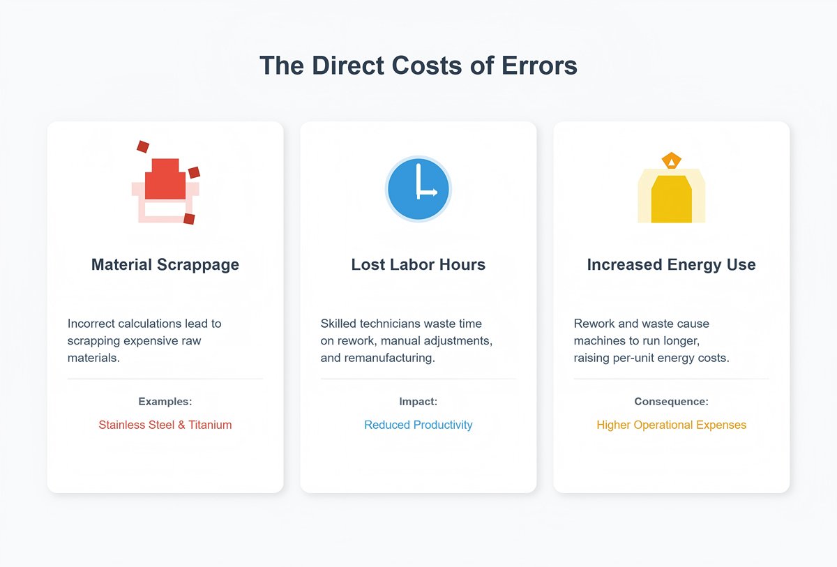
(1) Direct Costs:
1) Direct material scrappage: Incorrect flat pattern length calculations are the chief culprit in material waste. Especially in projects using high-value materials like stainless steel or titanium alloys, each bending error means the outright scrapping of expensive raw stock, directly hitting project profitability.
2) Lost labor hours: Rework is the nemesis of production efficiency. An incorrect bend angle or dimension may require skilled technicians to spend substantial time on manual adjustments, re-measurements, or even complete remanufacturing. These extra hours not only drive up labor costs but also steal valuable time that could have been used to produce acceptable products.
3) Increased energy consumption: Increased energy consumption: Whether it's driving a press brake, bending machine, or laser cutter, every operation consumes energy. Rework and waste mean machines must run idle or repeat cycles, significantly raising per-unit energy costs—a factor that’s especially critical in today’s high-energy-cost climate. For optimized bending performance and reduced rework, explore Air Bending: Precision Sheet Metal.
(2) Indirect Costs:
1) Disruptive chain reactions—production bottlenecks and sudden drops in efficiency: Reworked parts disrupt the established production rhythm, like a stone tossed onto a smoothly running conveyor, causing blockages. They occupy equipment, labor, and floor space, leading to delays in subsequent processes and a drop in overall output and efficiency.
2) The heavy price of tools and dies: Continuing bending errors may force a company to modify or remake costly stamping dies or press brake tools. What appears to be a simple angle correction could come with a price tag of thousands or even tens of thousands of dollars plus long lead times.
Additionally, improper operations (such as using the wrong tooling) can quadruple the required tonnage, significantly accelerating wear on machines and tools and reducing their service life.
3) Erosion of customer trust: Project delays and inconsistent product quality are two major taboos in business partnerships. Delivery delays caused by bending accuracy problems can seriously damage a client’s trust. One unpleasant experience may cost a company a long-term client or its market reputation—an intangible loss that is hard to quantify.
1.2 A Growth Blueprint Tailored for You
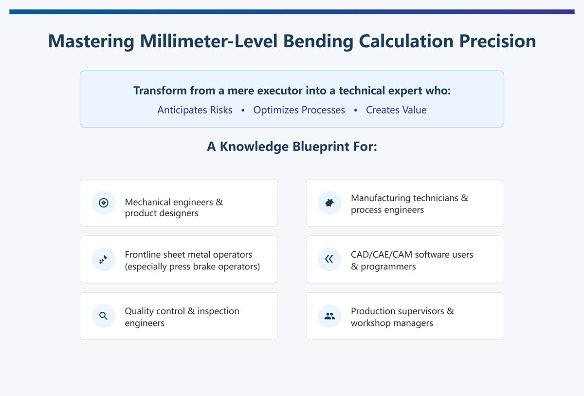
Mastering millimeter-level bending calculation precision transforms you from a mere executor into a technical expert who anticipates risks, optimizes processes, and creates value. This knowledge blueprint is designed for the following professionals:
- Mechanical engineers and product designers
- Manufacturing technicians and process engineers
- Frontline sheet metal operators (especially press brake operators)
- CAD/CAE/CAM software users and programmers
- Quality control and inspection engineers
- Production supervisors and workshop managers
Through deep study and practice, you will gain a comprehensive, powerful, and highly marketable skill set.
(1) Confidently calculate flat pattern lengths:
You will no longer rely on software’s “black box” defaults; instead, you will accurately set key parameters such as the K-Factor based on material properties, tooling, and processes, ensuring manufacturability right from the design stage.
(2) Optimize designs to avoid risks:
In the design phase, you will foresee potential manufacturing issues—such as holes placed too close to bend lines causing deformation, flanges too short to process, or bend radii that are too small causing material cracks—and design around them, eliminating waste at its source.
(3) Precisely diagnose error sources:
When dimensional deviations occur, you will be able to diagnose whether the cause lies in material springback, tool wear, machine inaccuracies, or calculation errors—just like a doctor diagnoses a patient—and propose effective solutions rather than making blind adjustments.
(4) Efficiently master software and tools:
You will truly understand the logic behind the sheet metal modules in CAD/CAM software, leverage advanced features, and even build a standardized material and process database for your company, vastly improving the design and manufacturing efficiency of the entire team.
Ultimately, what you gain is not just a calculation technique but a systematic way of thinking that bridges design and manufacturing, virtual and physical. This capability will make you an indispensable technical core of your company, playing a key role in cost control, quality improvement, and driving intelligent transformation.
II. Theoretical Cornerstone: The Trinity of K-Factor, Bend Allowance, and Bend Deduction
In precision sheet metal forming, every calculation revolves around a core question: how does the material deform during bending? To answer this, we must grasp three tightly connected core concepts: the K-Factor, Bend Allowance, and Bend Deduction. Together, they form the "trinity" that underpins bending calculations. Understanding their essence is the key to unlocking the door to precision manufacturing.
2.1 K-Factor: The “Heart” and Soul of Bending Calculations
If bending calculations form a precise system, then the K-Factor is undoubtedly its “heart.” It is the starting point for all flat pattern calculations, and its accuracy directly dictates the precision of the final product.
2.1.1 An Intuitive Look at the Neutral Axis
Imagine bending a thick rubber band. You’ll notice an interesting physical phenomenon:
The outer surface of the band stretches noticeably because it travels a longer path;
Conversely, the inner surface closer to the bend center gets compressed and wrinkled because it travels a shorter path.
Between this stretched outer layer and compressed inner layer lies a unique plane—its length remains almost unchanged before and after bending. This theoretical plane, which is neither stretched nor compressed, is called the neutral axis.
In sheet metal bending, the same principle applies. The length of the neutral axis stays constant, so if we can precisely determine the arc length of the neutral axis in the bend zone, we can accurately calculate the total flat length of the part. The entire purpose of the K-Factor is to locate this neutral axis.

2.1.2 Mathematical Definition of the K-Factor
The K-Factor is a dimensionless ratio that precisely defines the position of the neutral axis through the material's thickness. Its mathematical definition is simple:
K = t / T
Where:
- t = Distance from the neutral axis to the material’s inner surface (compression side).
- T = Total material thickness.
This formula tells us that the K-Factor is simply the ratio of the neutral axis location (t) to the total material thickness (T).
| K Value (K-Factor) | Meaning |
|---|---|
| K = 0 | Neutral axis coincides with the material’s inner surface (theoretical limit of compression). |
| K = 0.5 | Neutral axis is exactly at the midpoint of the sheet thickness. |
| K = 1 | Neutral axis coincides with the material’s outer surface (theoretical limit of tension). |
In actual cold bending, due to the ductility of metal, the neutral axis shifts toward the inside of the bend center, so the K value is always less than 0.5. For most metal materials, K values typically range from 0.3 to 0.5.

2.1.3 Debunking the Myth: Exposing the “Universal K-Factor (e.g., 0.447)” Industry Fallacy
Many CAD software programs (such as SOLIDWORKS and Inventor) have a default K value of 0.44 or 0.447. Many beginners, and even some experienced engineers, treat this as a “universal standard” or “industry truth,” applying the same value in all cases. This is a dangerous and costly misunderstanding.
The K-factor is not a universal, static constant but a dynamic variable influenced by multiple factors. Applying a fixed K-factor to all scenarios is one of the main causes of calculation errors and production waste. Below are the key variables that affect the K-factor:
(1) Material properties (hardness/ductility)
This is the most fundamental factor. Soft materials (e.g., soft aluminum, soft copper): High ductility, material flows and stretches more easily, the neutral axis shifts inward less, resulting in a higher K value, closer to 0.5. Hard materials (e.g., cold-rolled steel, stainless steel): Low ductility, greater resistance to deformation during bending, more severe inner-side compression, greater inward shift of the neutral axis, resulting in a smaller K value.
(2) Ratio of inner bend radius (IR) to thickness (T) (IR/T)
This is one of the most critical geometric factors determining the K value. Small-radius bends (sharp bends): When the bend radius is much smaller than the material thickness (e.g., IR < T), deformation is severe, the neutral axis moves significantly inward, and the K value is smaller. Large-radius bends (gentle bends): When the bend radius is much larger than the thickness (e.g., IR > 3T), the deformation process is gentler, the tension/compression difference between inner and outer layers decreases, and the neutral axis gradually returns toward the center (T/2), making the K value larger, approaching 0.5.
(3) Manufacturing process (bending method)
Different bending methods apply very different pressure and constraints to the material, directly changing its internal flow and stress state, thus affecting the K-factor.
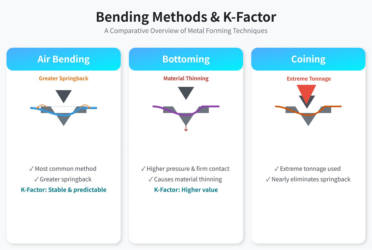
1) Air Bending: The most common method — the punch pushes the sheet into a V-die without fully contacting the bottom of the die. Springback is greater, and the K value is relatively stable and predictable.
2) Bottoming: The punch presses the sheet firmly into the bottom of the die, applying greater pressure. This causes thinning and extra plastic deformation, resulting in a higher K value.
3) Coining: Extremely high tonnage is used to “coin” the punch tip into the material, nearly eliminating springback. This extreme compression allows the material to fully flow, making the K value very close to or even reach 0.5.
There is no one-size-fits-all “golden K-factor.” Precision manufacturing requires companies to determine their own K-factor database for each specific combination of material, thickness, bend radius, and process—through testing (measuring actual samples) or by using reliable empirical charts. This is the scientific way to ensure millimeter-level accuracy from the start.
2.2 Bend Allowance (BA): The “Extra Length” Reserved for Bending
Once we understand that the K-factor is key to locating the neutral axis, bend allowance becomes the first core tool to put this theory into practice. Using an intuitive “addition” approach, it resolves the fundamental problem of calculating flat length.
The definition of bend allowance is very precise: it is the arc length of the neutral axis within the bend region.
Recall that the neutral axis is the only layer in the material that maintains its length during bending. Therefore, by adding the lengths of all flat sections to the bend’s neutral axis length (i.e., the bend allowance), we can determine the exact flat blank length required before bending.
It answers a key question: “How much material length do I need to reserve for a perfect bend?” That reserved length is the bend allowance.
(1) Bend Allowance (BA) Calculation Formula
The bend allowance is the arc length of the bend measured along the neutral axis of the sheet metal, since the neutral axis length remains unchanged after bending. It indicates how much additional length is generated by bend deformation.
Once the bend allowance is calculated, it is added to the flat lengths to determine the total sheet length needed to form the desired part.
As shown in the figure below:
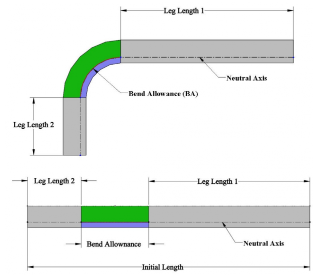
The following formula is used to calculate the flat length:
Sheet Metal Flat Length = Leg Length 1 + BA + Leg Length 2
The bend allowance calculation is essentially finding the length of a circular arc. The radius of this arc is the bend radius of the neutral axis.
The standard formula is:
Let’s break down each part of the formula:
1) A (or θ): Bend angle — the swept angle during bending, not the final inside angle of the part. For example, if a flat sheet is bent into a 90° angle bracket, the bend angle is 90°.
2) π/180: This is the conversion factor from degrees to radians, as arc length calculation requires radians.
3) IR (or R): Inner bend radius — the radius of the bend’s inner surface, usually determined by the die used.
4) T: Material thickness.
5) K: K-factor — the critical coefficient determining the neutral axis location.
6) (IR + K × T): The core of the formula. This calculates the bend radius of the neutral axis. K × T is the distance from the inner surface to the neutral axis (t), IR is the inner radius, and their sum gives the radius where the neutral axis lies.
2.3 Bend Deduction: The “Subtraction” Approach from Outer Dimensions
Contrasting with the “addition” logic of bend allowance, bend deduction offers an equally important but fundamentally different method— a “subtraction” logic. When the design starts from the part’s final outer profile dimensions, bend deduction becomes a more direct and efficient calculation tool.
In engineering drawings, we often use a part’s outer dimensions for annotation, as they determine whether it can fit precisely with other components. For easier calculation, we imagine extending the two outer surfaces of a bend until they intersect at an imaginary sharp corner.
Bend Deduction (BD) is defined as the difference between the sum of the two flange lengths extended to the imaginary apex and the actual flat length. In other words, it’s the adjustment we must “subtract” from the “virtual total length” to get the correct flat blank size. It answers the question: “How much longer is my measured virtual total length than the actual material needed?”

(1) Clear “Subtraction” Logic and Outside Setback (OSSB)
To fully understand this “subtraction” process, we must introduce a purely geometric concept: Outside Setback (OSSB).
- Definition of OSSB: Outside Setback is the distance from the virtual apex to the tangent point of the outer bend arc (where the bend begins).
- Essence of OSSB: OSSB is a purely geometric value. Its calculation depends only on the bend angle (A), the inside bend radius (IR), and the material thickness (T), and has nothing to do with the material’s physical properties (such as the K-factor). This is a critical feature—once the geometry is determined, OSSB is fixed.
The formula for OSSB is:
(2) The Unified “Master Formula”
Now we arrive at the most exciting part—linking together the “trinity” of K-factor, bend allowance, and bend deduction. Their relationship can be perfectly expressed through OSSB.
Bend Deduction (BD) = 2 × Outside Setback (OSSB)
This formula is at the heart of sheet metal bend calculation theory, revealing the internal logic behind all concepts:
1) 2 × OSSB: This value represents the total length that would be “double-counted” in the bend region if we naively added the two external flange dimensions. It is an overestimated purely geometric length.
2) BA: This value represents the actual arc length of material needed in the bend region, measured along the neutral axis. It is a physical and accurate length.
3) BD: Therefore, the deduction amount (BD) is the difference between the overestimated geometric length (2 × OSSB) and the true physical length (BA).
At this point, we have constructed a complete theoretical loop. Mastering this “trinity” framework gives you the powerful ability to perform precise bend calculations under any known conditions, completely freeing you from reliance on software “black boxes.”
For those who wish to delve deeper into this specific method, our Bend Deduction Calculation provides even more detailed examples.
2.4 The Ultimate Choice: BA vs. BD
Once you understand the respective principles of bend allowance (BA) and bend deduction (BD), a natural question arises: which should you use in practice?
This is not a winner-takes-all battle, but a strategic choice based on aligning design intent with workflow. They are both mathematical expressions of the same physical phenomenon and can be converted via formulas. Which one to choose depends on your design starting point and ultimate aim.
| Feature | Bend Allowance (BA) | Bend Deduction (BD) |
|---|---|---|
| Calculation Model | Addition logic: driven by internal dimensions | Subtraction logic: driven by outer profile dimensions |
| Core Definition | Actual arc length of the neutral axis in the bend area | Correction to subtract from the total length to the virtual apex |
| Application Scenario | Start from the flat sections of a part to calculate total flat length. Ideal for “designing from scratch.” | Start with the final outer dimensions and work backward to find flat size. Ideal for “following the drawing.” |
| Formula | Flat length = Straight leg 1 + BA + Straight leg 2 | Flat length = Outer size 1 + Outer size 2 - BD |
| Intuitive View | "How much material do I need to add for this bend?" | "How much length do I need to remove from this apex?" |
| Software Setup | In CAD software, usually the preferred high-accuracy option based on physical models (such as the K-factor). | In CAD software, can be entered directly, also common for shop floor manual setups or quick calcs from experience charts. |
| Applicable Industries | Used in aerospace, precision instruments, and other fields with extremely high demands for deformation control. | Widely used in general manufacturing, especially where assembly-driven design and fast response to customer drawings are needed. |
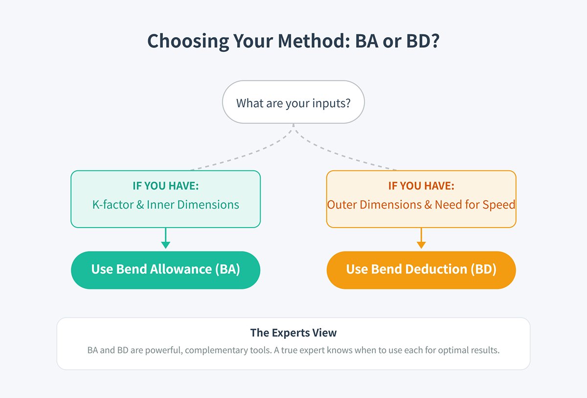
The choice between BA and BD can follow this simple decision guide:
- If you have the K-factor and inner dimensions → Use BA
- If you have outer dimensions and need quick calculation → Use BD
Bend allowance (BA) and bend deduction (BD) are neither better nor worse than each other; they are powerful tools for different situations. A true expert understands their intrinsic connection and can switch between them effortlessly based on the task at hand.
III. Diving Deep: Mastering All Variables that Affect Bend Accuracy
To truly achieve millimeter-level accuracy, we must look beyond surface formulas and dive into the microscopic world inside the material, understanding its “resistance” and “compromise” under massive external forces. This chapter builds from the fundamentals of material mechanics and geometry to reveal the “why,” enabling you not only to know what happens, but why it happens—equipping you to anticipate and solve challenges in complex conditions.
3.1 The Microscopic World of Bending: A Journey of Plastic Deformation
The moment the press brake punch contacts the metal sheet, a microscopic “tug-of-war” begins. The fate of the sheet is determined by the contest between internal stresses and external forces.
(1) Tensile Zone, Compression Zone, and the Dynamic Balance of the Neutral Axis
At the instant of bending, metal grains on the outer side of the bend are pulled apart, creating a tensile zone, while those on the inner side are heavily compressed, forming a compression zone.
Between these two zones lies a theoretical layer that is neither significantly stretched nor compressed—the neutral axis. This is where tensile and compressive stresses cancel out to reach dynamic balance, and its location determines everything in bend calculations.
(2) The Cause of Springback
Metal is not as compliant as dough. To understand springback, we must bring in the stress-strain curve of the material.
In the initial stage of applied pressure, the metal undergoes elastic deformation. If the force is released at this point, it will fully return to its original shape, like a spring.
When the applied force exceeds the material’s yield strength, the metal enters the plastic deformation stage, resulting in permanent changes in shape—this is the “forming” we aim for.
However, once we release the pressure from the press brake, the elastic stress stored within the material is released. This elastic recovery causes the material to partially return toward its original shape, resulting in a final bend angle that is always smaller than the target angle set on the machine, and a final bend radius that is always greater than the die radius. This phenomenon is known as springback.
Springback is an inherent and unavoidable occurrence in all bending processes. The amount of springback is directly related to two key material properties:
1)The higher the yield strength, the greater the springback
Materials such as high-strength steel (HSS) require more force to yield, which means greater elastic stress is stored inside. Once the load is released, the springback is naturally more pronounced.
2)The lower the elastic modulus, the greater the springback
The elastic modulus measures a material’s resistance to elastic deformation. Under the same stress, materials with a lower elastic modulus (such as aluminum) undergo greater elastic strain, resulting in more noticeable springback.
3.2 Common Misconceptions Clarified: Correcting Deep-Rooted Errors
A thorough mastery of theory ultimately shows in the ability to avoid practical mistakes. Below are three widely spread and potentially harmful misconceptions in the sheet metal industry that must be corrected.
(1) Confusing Bend Angle, Internal Angle, and Included Angle
When discussing bends, descriptions of angles often cause confusion, making this a common source of calculation errors.
1) Bend Angle: This is the angle used in formulas, referring to the swept angle of material during bending. For example, bending a flat plate into a 90° right angle means the bend angle is 90°.
2) Included Angle: This refers to the internal angle between two flanges after bending is complete. For a 90° right angle, the included angle is also 90°. But for a sharper 30° bend, the included angle is 30°.
3) Complementary Angle: This is the supplementary angle to the included angle (180° − included angle). Some press brake control systems or calculation charts may use this value.
In BA and BD formulas, A represents the “bend angle.” If you mistakenly enter a 30° included angle into the formula, your results will be significantly incorrect.
The correct approach is: if you need a 30° included angle, the material’s sweep (bend angle) is
180° − 30° = 150°. You must use 150° for calculation.
(2) Ignoring Springback and Directly Using the Target Angle for Calculations
This is a subtler yet equally fatal error, stemming from neglecting the physical properties of materials.
Metal bends always experience springback, meaning that to achieve an exact final angle of 90°, you must set a smaller angle on the press brake (for example, 88° or 89°), overbending so that it returns precisely to 90° after springback.
In formulas, the “bend angle A” should be the actual execution angle on the machine — that overbend angle — because the deformation (tension and compression) occurs at that specific execution angle.
Accurate manufacturing requires engineers to either predict or determine springback through test bends, and then use the compensated angle for flat length calculations.
IV. Hands-On Practice: From Zero to Precision Calculations
The true value of deep theoretical understanding is proven through practical application. This chapter, the core practical module of the guide, transforms theory into an executable set of calculation steps and application instructions. We will start from scratch, guiding you step-by-step through a complete precision flat length calculation, and show you how to integrate this knowledge into your daily tools so you can fully master this critical skill.
4.1 Step-by-Step Guide: Walkthrough to a Perfect Calculation
Now, let’s put theory into practice.
Scenario Setup
- Task: Calculate the flat blank length for an L-shaped bracket.
- Part: Final outer dimensions are 50 mm × 50 mm for the L-shaped bracket.
- Material: 304 stainless steel.
- Thickness (T): 2.0 mm (measured).
- Target internal radius (R): 3.0 mm (determined by tooling).
- Bend angle (A): 90° (springback accounted for; this is the execution angle on the machine).
(1) Step One: Determine the K-Factor
This is the most critical first step. For a hard material like 304 stainless steel, the K-factor is usually relatively small. Without measured data, we can refer to reliable sources or charts. Databases show that for stainless steel with an R/T ratio (3.0/2.0 = 1.5) between 1 and 2, a K-factor of 0.44 can be used as a starting point.
(2) Step Two: Calculation via Bend Allowance (BA) Method
The core of the BA method is an “additive logic” that starts from the flat portions of the part and adds the length of the bend region. For this, we first calculate two key values: Bend Allowance (BA) and Outside Setback (OSSB).
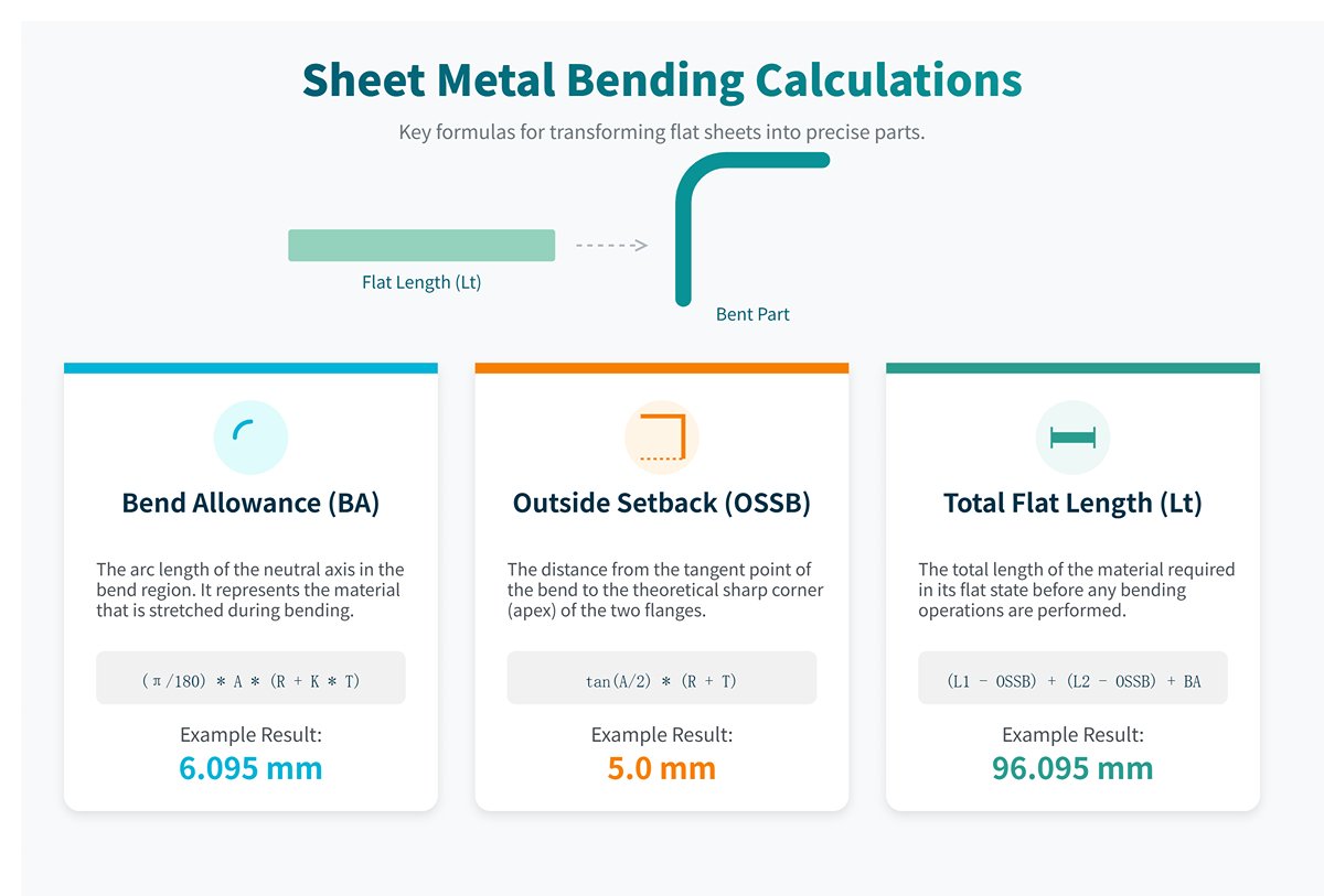
1) Calculate Bend Allowance (BA)
BA = (π/180) * A * (R + K * T)
Substitute values: BA = (3.14159 / 180) * 90 * (3.0 + 0.44 * 2.0) ≈ 6.095 mm
This represents the arc length of the neutral axis in the bend region: 6.095 mm.
2) Calculate Outside Setback (OSSB)
OSSB = tan(A/2) * (R + T)
Substitute values: OSSB = tan(90/2) * (3.0 + 2.0) = tan(45°) * 5.0 = 5.0 mm
This is the distance from the theoretical apex to the bend start point: 5.0 mm.
3) Calculate Flat Length (Lt)
In the BA method, total length = Leg length 1 + Leg length 2 + BA.
The length of each flat leg equals the outer dimension minus OSSB.
Leg length 1 = Outer dimension 1 - OSSB = 50 - 5.0 = 45.0 mm.
Leg length 2 = Outer dimension 2 - OSSB = 50 - 5.0 = 45.0 mm.
Total flat length Lt = 45.0 + 45.0 + 6.095 ≈ 96.095 mm
(3) Step Three: Calculation via Bend Deduction (BD) Method
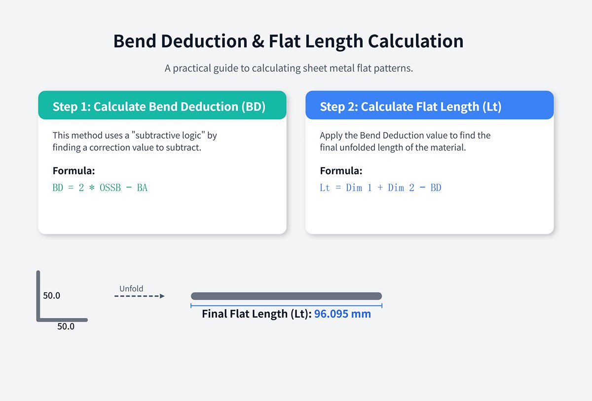
1) Calculate Bend Deduction (BD)
The BD method’s core is a “subtractive logic” — starting from the sum of the outer dimensions and subtracting a correction value.
BD = 2 * OSSB − BA
Substitute values: BD = 2 * 5.0 − 6.095 ≈ 3.905 mm
This means that to get the correct flat length, you must subtract 3.905 mm from the sum of the outer dimensions.
2) Calculate Flat Length (Lt)
In the BD method, total length = outer dimension 1 + outer dimension 2 − BD.
Total length = Outer dimension 1 + Outer dimension 2 − BD.
Substitute values: Lt = 50.0 + 50.0 − 3.905 ≈ 96.095 mm
(4)Step Four: Result Verification and Conclusion
| Calculation Method | Formula | Calculation Process | Final Flat Length (Lt) |
|---|---|---|---|
| Bend Allowance Method (BA) | (L1 − OSSB) + (L2 − OSSB) + BA | (50 − 5) + (50 − 5) + 6.095 | 96.095 mm |
| Bend Deduction Method (BD) | L1 + L2 − BD | 50 + 50 − 3.905 | 96.095 mm |
The two methods ultimately lead to the same result, which powerfully demonstrates the consistency of the theory. Mastering the calculations and intrinsic relationship between these two approaches means you now have the ability to perform precise and reliable bending calculations in any situation, successfully transforming theoretical knowledge into a powerful practical skill.
For detailed specifications on equipment that can help you standardize these variables, feel free to download our Brochures.
4.2 How to Obtain Your Own “True K-Factor”
(1) Authoritative Chart Method
In the early stages of a project, for quick estimates or in cases where high precision is not required, referring to authoritative K-factor charts is an efficient approach. These charts are typically compiled from extensive experimental data and provide reference K-factor values for different materials under various bend radius-to-thickness ratios (R/T).
Important Warning: The table below is by no means a universal “standard answer.” It should only serve as a starting point for your calculations or an educated guess. Real workshop conditions (such as die wear or material batch variations) will inevitably cause deviations.
K-Factor Reference Table
| Material Type | R/T Ratio (Radius/Thickness) | Typical K-Factor Range |
| Soft Materials | R < T | 0.35 - 0.40 |
| Aluminum (5052, 6061) | ||
| T ≤ R < 3T | 0.40 - 0.45 | |
| R ≥ 3T | 0.45 - 0.50 | |
| Medium Hardness Materials | R < T | 0.38 - 0.42 |
| Low Carbon Steel/Cold Rolled Steel | ||
| T ≤ R < 3T | 0.42 - 0.46 | |
| R ≥ 3T | 0.46 - 0.50 | |
| Hard Materials | R < T | 0.34 - 0.40 |
| Stainless Steel (304, 316) | ||
| T ≤ R < 3T | 0.40 - 0.44 | |
| R ≥ 3T | 0.44 - 0.50 |
(2) Precision Test Bend — The Path to Professionalism
The only way to obtain a K-factor that truly represents your production capabilities is through physical testing. This process, known as the empirical method, transforms you from an operator relying on external data into an expert capable of building a core process database for your company.
Goal: Create an accurate test piece to reverse-calculate the true K-factor for your specific combination of equipment, tooling, and material.
Step-by-step guide:
Step 1: Prepare the test coupon. Material: Must be cut from the same batch of sheet metal intended for mass production. Dimensions: Prepare several identical rectangular strips, each long enough (at least 300 mm recommended) for accurate measurement and of moderate width (e.g., 50 mm). Ensure edges are smooth and burr-free. Measurement: Use a micrometer to precisely measure the actual thickness (T) and blank length (Lt) of the samples, and record them as your baseline values.
Step 2: Perform a standard bend. Tooling: Use the same press brake and tooling set you will use in production. Operation: Bend the sample precisely to a 90° angle. This is the most ideal and straightforward reference angle for reverse calculation. Goal: Achieve a finished piece with an included angle exactly at 90°. You may need to slightly “overbend” (e.g., to 89°) to compensate for material springback.
Step 3: Precisely measure the finished piece. This is the most critical step and requires extreme accuracy. Measure the following three dimensions: Flange lengths (L1 and L2): Precisely measure the external lengths of both flanges after bending. Inside bend radius (R): Use a radius gauge or optical comparator to accurately measure the actual inside radius. Sheet thickness (T): Reconfirm the thickness.
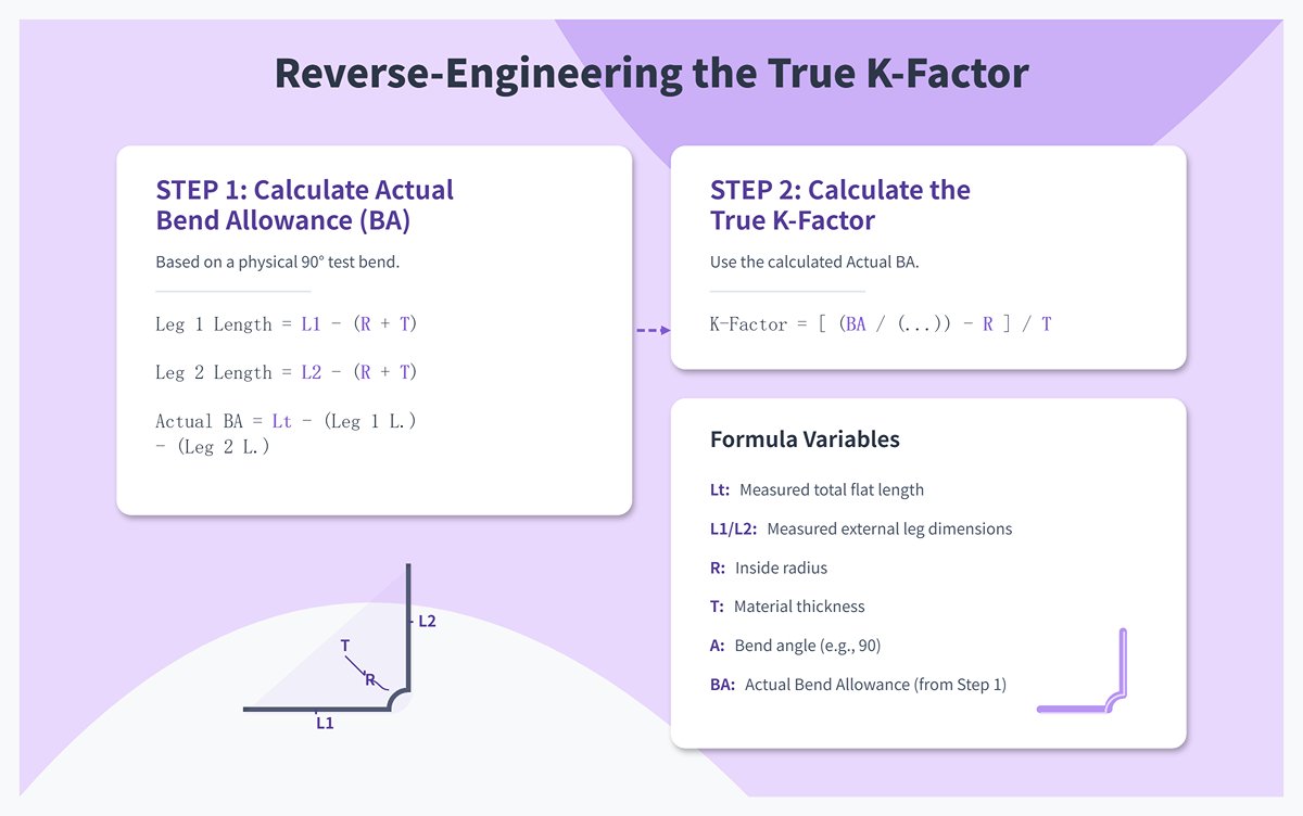
Step 4: Reverse-calculate the bend allowance (BA). Now we have all the data needed to compute the actual bend allowance. We know:
Total flat length (Lt) = Leg length 1 + Leg length 2 + BA,
Leg length = External dimension − Outside setback (OSSB),
where OSSB = R + T for a 90° bend.
Therefore: Leg length 1 = L1 − (R + T), Leg length 2 = L2 − (R + T).
Substituting into the flat length formula, we can solve for the actual bend allowance (BA):
BA_actual = Lt − (L1 − (R + T)) − (L2 − (R + T))
Step 5: Reverse-engineer the “True K-Factor.” With the actual BA value determined, we can now use the original BA formula to solve for K.
Original formula: BA = (π/180) * A * (R + K * T)
Rearrange the formula to solve for K:
K_true = [ (BA_actual / ((π/180) * A)) − R ] / T
By substituting the BA_actual, A (90°), R, and T values obtained in Steps 3 and 4 into this formula, you will get a highly precise “True K-Factor” unique to your process, accurate to several decimal places.
V. Complex Scenarios, Troubleshooting, and Optimization Strategies
After mastering the fundamental theory and standard calculations, you have successfully stepped into the professional realm. But to become a true expert capable of solving complex problems and creating core value, you must learn to navigate non-standard scenarios with ease, diagnose issues systematically like a detective, and consistently optimize processes like a strategist. This chapter focuses on the key challenges faced by advanced users, helping you make the leap from “proficient” to “mastery.”
5.1 Advanced Tips: Beyond 90-Degree Bends
(1) Acute/Obtuse Angle Bending
1) Universality of the Formula
First, understand that the underlying mathematical logic of the bend allowance (BA) and bend deduction (BD) formulas we’ve learned applies to any angle.
2) The Most Critical Pitfall
Angle confusion! The most common mistake inexperienced engineers make is misunderstanding “angle A” in the formulas. Commit this to memory: In the formula, A is always the bend angle swept by the material, not the final included angle of the finished part!
Acute bend example:
Suppose you need a V-shaped part with a final included angle of 60°. In this case, the bend angle swept by the material A = 180° − 60° = 120°.
In your calculation, you must use 120°, not 60°. Obtuse bend example: If you need an obtuse-angled part with an included angle of 135°,
then the actual bend angle swept by the material A = 180° − 135° = 45°. This is the angle that should be used in the formula.
3) Process Challenges
Hemming is an extreme form of acute bending, typically folding the sheet edge completely over itself to increase edge stiffness or eliminate sharp edges. It usually involves two steps:
First, bend to a very sharp angle (e.g., 30°), then flatten it using a hemming die. Calculating the flat length in this case requires specialized experience or bend charts, as the material undergoes significant plastic deformation during flattening.
(2) Springback Compensation: Battling the “Will” of the Material
Springback is the inherent “archenemy” in all bending processes, and accurately predicting and compensating for it is central to high-precision manufacturing.
| Method Category | Description & Principle | Specific Measures / Examples | Features & Advantages |
|---|---|---|---|
| Over-bending | Set a bending angle slightly smaller than the target, leveraging the material's springback so it returns precisely to the desired angle. | For a target angle of 90°, set the bending angle to 88°. | The most straightforward and widely used method, relies on experience or test data. |
| Process Parameter Adjustment | Optimize various parameters in the bending process to suppress springback, allowing more time for plastic deformation. | Reduce punching speed. Increase dwell time. Apply higher clamping force (e.g., switch from air bending to bottoming). | Controls errors during processing, improves forming accuracy. |
| Software & Simulation | Use digital tools for prediction and real-time correction to achieve precise control. | Pre-production prediction: Use CAE software with Finite Element Analysis (FEA) to predict springback and apply digital compensation. Real-time correction: Modern CNC press brakes integrate laser angle measurement systems to measure in real time and automatically adjust the next bend. | High precision, high automation, reduces trial-and-error costs in the early stage. |
5.2 Fault Diagnosis Checklist: How to Systematically Troubleshoot Incorrect Unfolded Dimensions
When the first produced part has incorrect dimensions, avoid blindly tweaking machine settings like a headless chicken. A true expert, like an experienced doctor, follows a systematic diagnostic procedure—starting from the most likely and easiest causes, checking step-by-step to accurately pinpoint the root problem. For a deeper dive into common issues, our guide on The 8 Common Press Brake Bending Problems provides additional insights.
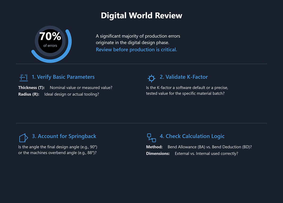
(1) Digital World Review
Seventy percent of errors originate here. Before touching any physical equipment, thoroughly review your digital blueprint.
1) Are the basic parameters “measured values”? Thickness (T): Are you using the nominal thickness (e.g., 2.0 mm) or the average measured with a micrometer at multiple points on the material (e.g., 2.03 mm)? Radius (R): Are you using the ideal radius from the drawing, or your actual tooling radius? Tools wear and radii change over time.
2) Has the K-factor been validated? Are you using the software's default value, or the precise “true K-factor” obtained from the “precise test bend method” in Section 4.3, tailored to your current material batch and equipment?
3) Have you accounted for springback in the angle? Is the angle in your calculation the final target design angle (90°), or the actual overbend angle (88°) used on the machine to compensate for springback?
4) Is there confusion in the calculation logic? Quickly re-check your math. Have you mixed up the formulas for Bend Allowance (BA) and Bend Deduction (BD)? Have you mistakenly used external dimensions where internal dimensions were required?
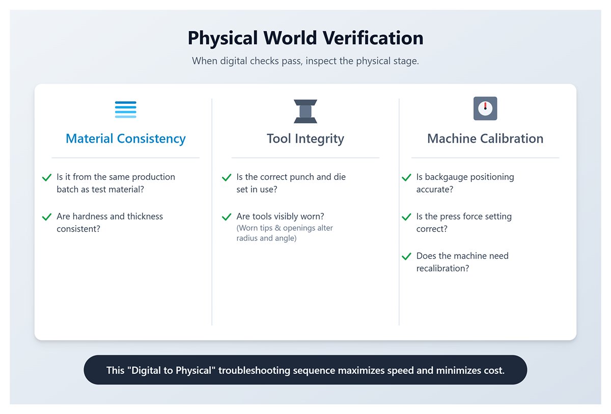
(2) Physical World Verification
If the digital world checks out perfectly, then the issue must lie in the physical processing stage.
1) Is the material consistent? Is the production material from the same batch as the material used for your testing or calculations? Even minor differences in hardness and thickness between batches can be critical.
2) Are the tools matched and intact? Did the operator use the correct punch and die set? Is either tool visibly worn? Worn punch tips will have larger radii, and deformed V-shaped openings can cause the actual forming radius and angle to deviate from theoretical values.
3) Is the machine calibrated? Is the press brake's backgauge positioning accurate? Is the press force setting correct? Does the machine itself require recalibration?
This troubleshooting sequence—from “digital” to “physical”—will help you find the root cause with maximum speed and minimum cost, rather than groping in the dark with guesswork.
Ⅵ. Conclusion
The essence of sheet metal manufacturing lies in mastering the following principles: The K-factor is the foundation—a dynamic parameter affected by material, process, and geometry, never a fixed value; BA and BD are methods—bend allowance and bend deduction are equivalent calculation paths, and you must be adept at converting between them; Physical test bending is the gold standard—deriving the “true K-factor” from real-world tests on a reliable press brake is key to building a high-precision, customized process database. Only by understanding the underlying algorithms can you control them effectively rather than follow them blindly.
In the future, sheet metal manufacturing will deeply integrate with AI and simulation. Finite Element Analysis (FEA) will accurately predict springback and stress in a virtual environment, significantly reducing physical trial and error; Artificial Intelligence (AI) will learn from historical data to autonomously recommend optimal K-factors and process parameters, becoming a “virtual process master.” Parameters such as the K-factor will evolve into core digital threads driving smart factories, with data flowing seamlessly from design, through ERP and MES systems, directly to the machine control of an advanced CNC Press Brake—continuously optimized via real-time sensor feedback.
This transformation marks a shift in manufacturing from experience-driven to data-driven, from single-point optimization to full-chain collaboration. Manufacturing experts who deeply understand the core principles will be the key force leading this era of precision manufacturing driven by data and intelligence. If you aim to be at the forefront of this evolution, contact us to explore how our advanced solutions can empower your production.


