I. Introduction
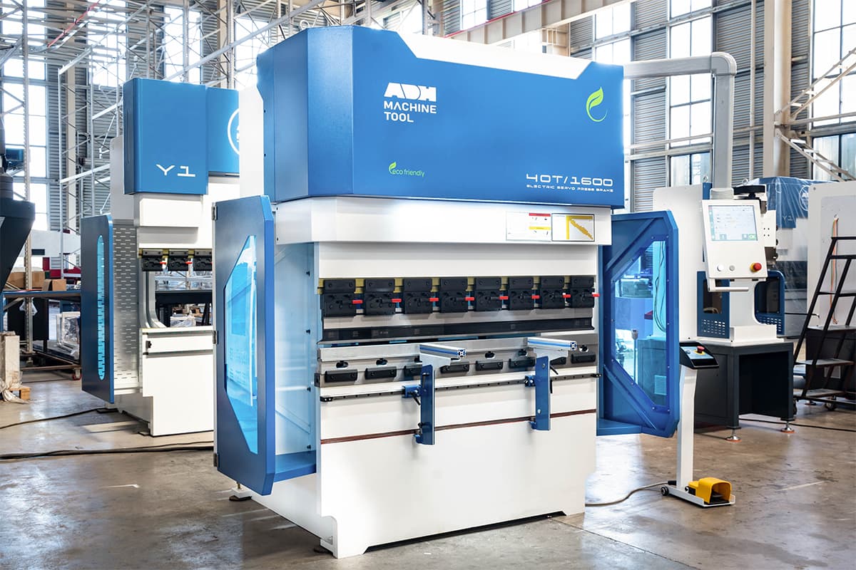
The CNC press brakes are indispensable and sophisticated sheet metal processing machines that require precise operation under the hydraulic control of both a CNC controller and an operator in the sheet metal fabrication and manufacturing industries. It is important to carefully set the necessary parameters and procedures before beginning a bending job.
However, even with proper preparation and maintenance, the press brake bending machines can still experience mechanical failures over time. Common issues include vibrations during bending, oil pump leaks, and inaccurate size and shape of the finished workpieces, leading to material waste and even damage to the machine.
Inaccurate bending not only leads to defects but also adds cost. For detailed guidance on enhancing bending precision, you can refer to How to Improve Press Brake Bending Accuracy.
In some cases, these faults can also pose a risk to the safety of the operator. In this blog, we will explore the reasons for press brake bending problems and offer tips on how to prevent and avoid them.
II. Building a Systematic Bending Mindset
In the world of precision manufacturing, a press brake operator is like a sculptor, breathing precise form and life into cold sheets of metal. Yet, the road to perfection is littered with pitfalls: angle deviations, inconsistent dimensions, surface scratches… Each failed bend is an expensive exercise in "trial and error." Too often we treat problems in isolation—patching one symptom at a time—without pausing to wonder: could there be a deeper, systemic cause behind these seemingly unrelated issues?
The purpose of this guide is to help you escape that endless “fix-it loop.” Our goal is not simply to solve problems as they arise, but to build a mindset that can anticipate, prevent, and eliminate them at their root.
1. Rethinking Cost
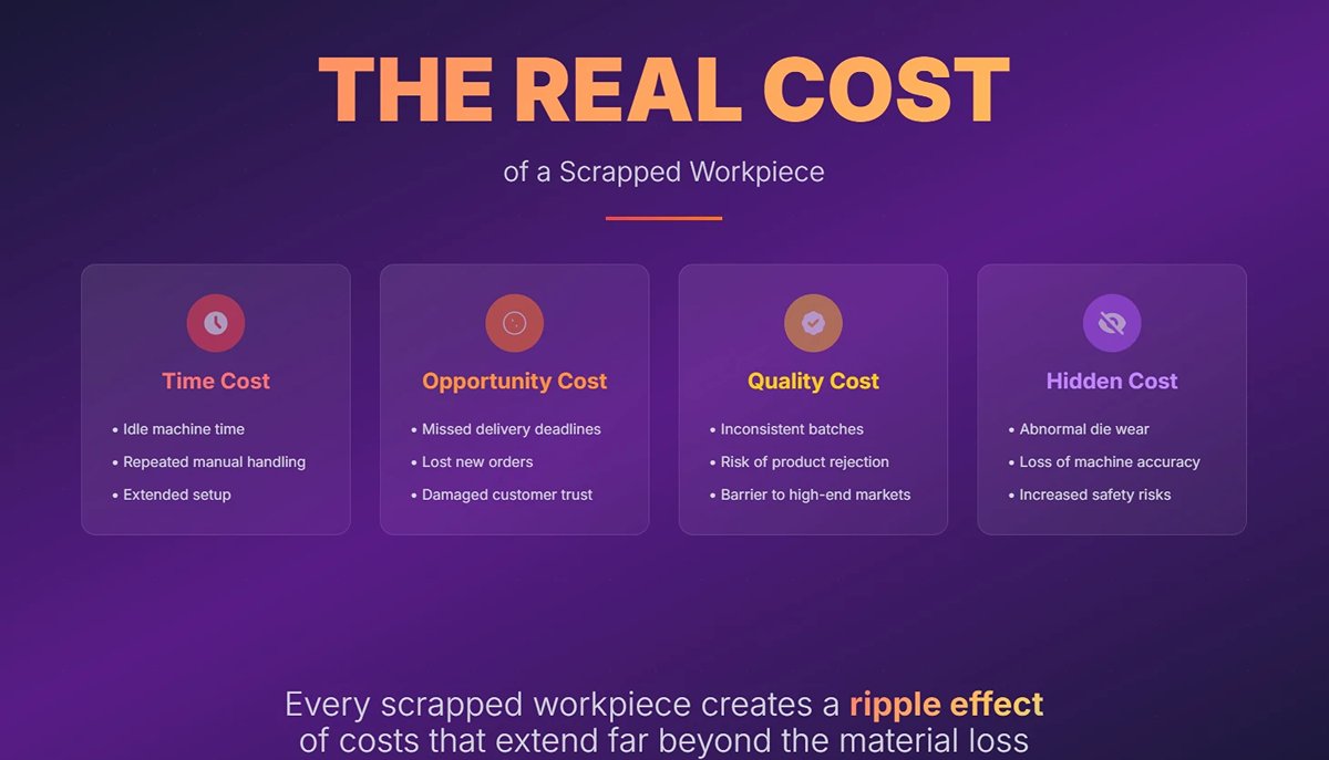
What is the real cost of a scrapped workpiece lying quietly in the scrap bin? If your first thought is just the price of the material, you may be overlooking an iceberg large enough to sink your profits.
A single misbend triggers a chain reaction of hidden expenses:
(1) Time cost
Idle machine time, repeated manual handling, and extended setup all drain productivity in ways that can never be recovered.
(2) Opportunity cost
When production stalls for rework, you lose more than just time—you lose on-time delivery commitments, chances to win new orders, and, most critically, customer trust.
(3) Quality cost
Inconsistencies between batches mean your product quality hovers on the fine line between “passable” and “scrap,” a fatal weakness for any business aiming at high-end markets.
(4) Hidden cost
Abnormal die wear, accelerated loss of machine accuracy, and even increased safety risks caused by operator frustration
These unseen losses quietly accumulate, driving up your total operating costs.
Pursuing zero-defect bending is not an empty slogan—it’s a core competitive advantage for survival and growth. Recognizing this fact is the first step to adopting a truly systematic way of thinking.
To learn practical cost-saving bending strategies and reduce trial-and-error waste, see Advanced Press Brake Techniques.
2. The Golden Triangle of Bending
Picture a sturdy triangle whose three vertices are the machine, the tooling, and the material. This is the “Golden Triangle” of bending. More than 90% of bending problems can be traced back to an imbalance among these three points or to a fault at one of them.
(1) Machine
The machine is the source of both power and precision. Its rigidity, the backgauge’s positioning accuracy, the stability of the hydraulic system, and the effectiveness of the deflection compensation system together determine the upper limit of bending quality. A poorly maintained or misaligned machine is like a building with an unstable foundation—no matter how beautiful the structure above, it will inevitably lean.
(2) Tooling
Tooling is the direct executor of the process. The material, hardness, precision, tip radius (R-angle), and alignment of the upper and lower dies directly define the bend angle, radius, and the surface finish of the workpiece. Serving as the “translator” between machine and material, any wear, damage, or incorrect choice in tooling distorts the message.
(3) Material
Material is the least predictable variable in the process. Thickness tolerance, yield strength, ductility, and grain direction (creating anisotropy) all directly affect the bending result—especially springback. Ignoring a material’s “personality” and trying to apply one fixed set of parameters to every job is a key cause of instability in batch production.
Stop blaming an inaccurate angle setting or a misplacement by the operator in isolation. Whenever you face a defect, immediately visualize the “Golden Triangle” and ask yourself: is the issue with the machine’s precision, the choice of tooling, the nature of the material—or is it the interplay between them?
3. Shifting from Reactive Fixes to Proactive Prevention
Mastering the Golden Triangle gives you a clear roadmap toward bending expertise. This journey unfolds in three levels of thinking:
(1) Reactive fixing
This is where most people start. A problem arises, and you scramble to find a fix, making adjustments based on experience and instinct. Like a firefighter constantly chasing flames, you’re always reacting, never anticipating—an inefficient and uncertain way to work.
(2) Systematic diagnosis
This is the stage this guide aims to bring you to. You approach issues like a detective, using the Golden Triangle as your logical framework, reasoning step-by-step from the symptoms to the true cause. No more blind trial and error—your adjustments are guided by scientific analysis.
(3) Proactive prevention
This is the ultimate goal. You not only fix problems but anticipate and stop them from occurring. By establishing standardized operating procedures (SOPs), preventive maintenance plans (PM), and a database of process parameters for your commonly used materials, you build a stable, reliable, and efficient production system. You’re no longer managing problems—you’re managing the system.
In the upcoming sections, we’ll explore eight of the most common bending defects. But remember—our aim is not just to give you an “answer sheet.” We’ll be using each case to train your ability to think independently and solve problems through the Golden Triangle approach.

Ⅲ. Solving Common Press Brake Problems
Now we move from strategy to tactics. With the Golden Triangle mindset in hand, we’ll dissect eight “classic scenarios” that play out daily on the shop floor. This isn’t just a troubleshooting checklist—it’s a step-by-step diagnostic method. For each problem, we’ll strictly follow the path: symptom identification → root cause analysis → solution, taking you from surface-level effects to the underlying cause, and from reactive response to proactive control.
1. Issue One: Inaccurate Angles and Uncontrolled Springback
This is one of the most common—and most frustrating—challenges in bending. Like an elusive phantom, it undermines consistency in mass production.
(1) Symptom identification
Measurements reveal that the bend angle consistently overshoots (excessive springback) or undershoots (over-bending) the target specification. Even within the same batch, angle variations exceed acceptable tolerance limits.
(2) Root Cause Analysis
Springback occurs when a material’s internal elastic–plastic deformation recovers after external force is removed. Its magnitude is primarily determined by the following “golden triangle” factors:
1)Material (The Root Cause)
This is the most critical factor. The higher the yield strength and the thicker the material, the more pronounced the springback. Variations in thickness tolerance and hardness within the same batch are direct causes of inconsistent springback.
2)Tooling (The Controller)
The V-die opening width in the lower die is pivotal. A wider V-opening increases the internal bend radius during free bending, which in turn amplifies springback. The widely accepted “8× rule” (V-opening roughly eight times the sheet thickness) strikes the ideal balance between bending force and springback. Additionally, wear on the punch tip radius or the lower die shoulders alters contact geometry and can destabilize springback performance.
3)Machine (The Executor)
A press brake with insufficient rigidity will undergo slight deflection under load, which springs back upon unloading and adds to the material’s own springback. Minor hydraulic pressure fluctuations can directly translate into variations in bending depth, causing angular inconsistencies.
(3) Solutions
1)Immediate Adjustment
Leverage the angle compensation features of modern CNC press brakes. By test-bending one or two parts, measuring the deviation from the target angle, and entering the compensation value into the system, subsequent bends are automatically corrected via adjusted ram depth.
2)Process Optimization
Establish a springback database: For your most frequently used materials (grade and thickness), systematically record springback data under various V-opening widths. This becomes a “first-principles” resource for programming new jobs. Use the “over-bend” or “coining” method: In high-precision scenarios, over-bending intentionally to a smaller angle allows springback to settle exactly at the target. Coining applies extremely high pressure—typically 5–10× that of free bending—to plastically form the material in the die, virtually eliminating springback, though it demands exceptionally high tonnage and tool strength.
3)Long-Term Strategy
Invest in CNC press brakes with real-time angle measurement and automatic compensation. These machines use laser or contact probes during the bend to measure angles and adjust ram depth within the stroke, effectively neutralizing material variability.
For high-strength steels such as Hardox or Weldox with severe springback, choose a smaller V-opening and a premium press brake with variable-frequency pressure control to fine-tune force during the dwell phase, significantly reducing springback.
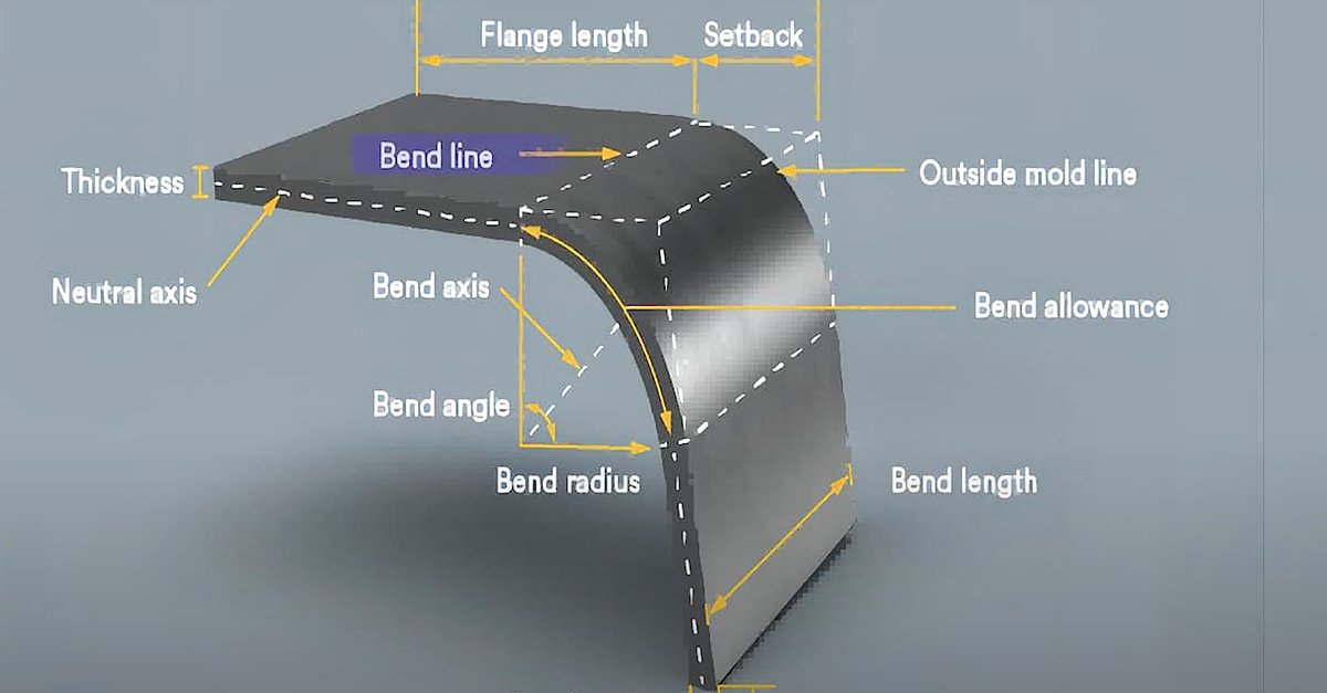
2. Issue Two: Inconsistent Flange Lengths
This problem directly compromises assembly accuracy, making it the second most critical quality killer.
(1) Symptom Identification
Within a single batch of parts, measurements from the bend line to the workpiece edge show flange lengths fluctuating beyond tolerance limits.
(2) Root Cause Analysis
The core issue is the stability of the positioning reference.

1)Machine (The Positioner)
The backgauge system is often to blame. Wear in its lead screws or racks, servo motor positioning errors, or loose/deformed stops can all introduce slight deviations in each positioning cycle.
2)Operation (The Human Factor)
If the operator fails to ensure that the workpiece edge is firmly and fully seated against the backgauge stops, slight misplacement can occur. Excessive feed speed or angled placement adds random error.
3)The Workpiece Itself (The Object)
The locating edge may have burrs, be uneven, or the workpiece may be warped, preventing proper flat contact with the backgauge.
(3) Solutions
1)Equipment Calibration
At least quarterly, use gauge blocks or dedicated calibration tools to verify and adjust the positioning accuracy and repeatability of the backgauge’s X-axis (front–back), R-axis (up–down), and Z-axis (left–right).
2)Process Improvements
Select backgauge fingers suited to the part’s geometry. For flanged parts, use tall narrow fingers; for angled edges, use swiveling universal fingers. Optimize the CNC program so the backgauge completes its movement before the part is loaded, avoiding collisions.
3)Operational Standardization
Implement a standard operating procedure (SOP) requiring operators to follow "light–push–secure": gently place the part, lightly push forward until firmly against the stop, and visually confirm proper contact.
3. Issue Three: Cracks or Orange Peel Texture on Outer Bend Radius
This is the material’s way of sending a distress signal. It not only mars the appearance but can also compromise structural integrity.
(1) Symptom Identification
On the outside of the bend, fine cracks appear—sometimes progressing to full breaks. Alternatively, the surface develops a rough, dimpled texture resembling orange peel.
(2) Root Cause Analysis
The underlying cause is deformation exceeding the material’s ductility limit.
1)Bend Radius Too Small
This is the most common culprit. Every material has a minimum bend radius, usually a multiple of its thickness. When the punch tip radius is much smaller than this limit, the outer fibers are overstretched, leading to cracking.
2)Bending Along the Rolling Direction: Sheet metal develops directional grain structure during rolling, reducing ductility parallel to the grain. Bending along this direction greatly increases cracking risk.
3)Material-Related Issues: Selecting the wrong grade (low ductility) or using material with internal impurities or lamination defects.
(4) Solutions
1)Direction Optimization
Plan bend orientation during nesting so that critical bends are as perpendicular as possible to the rolling direction. If bending parallel is unavoidable, choose a punch tip radius far greater than the minimum requirement.
2)Tooling Match
Follow the supplier’s recommended minimum bend radius. As a rule of thumb: for mild steel, punch radius ≥ material thickness (t); for aluminum alloys and stainless steel, 1.5t to 2t—or even larger—may be needed.
3)Material Treatment
For harder materials, localized annealing before bending can enhance ductility if the process allows. If cracking persists, the only viable option is to work with design to source a higher-ductility material grade.
4. Issue Four: Surface Scratches, Impressions, and Damage
For appearance-critical products like stainless steel, aluminum sheets, or pre-painted panels, this is a fatal flaw.
(1) Symptom Identification
Visible scratches, shiny marks, or deep impressions appear on the workpiece surface—particularly in areas contacting the lower die shoulders.
(2) Root Cause Analysis
The primary cause is relative sliding and excessive pressure between the workpiece surface and the tooling.
1)Tooling Condition
The shoulder radii of the V-die in the lower tool may have worn sharp from prolonged use, or the die surface may be contaminated with metal debris or rust—acting like sandpaper on the workpiece surface.
2)Process Pressure
Excessive bending force—especially approaching bottoming—causes the lower die shoulders to bite deeply into the material surface.
3)Material Properties
Soft metals such as aluminum and copper, as well as surface-sensitive materials like mirror-finish stainless steel, are naturally more prone to scratches.

(3) Solutions
1)Surface Protection (Zero-Cost Option)
Apply a non-marking protective film (a high-wear-resistant polyurethane film) to the lower die surface. This creates a cushioning barrier between the tool and the workpiece, effectively preventing scratches and impressions. It’s a low-cost yet highly effective solution.
2)Tooling Upgrade
Use specialized non-marking lower dies equipped with nylon inserts or rotating blocks. The die shoulders, made from high-hardness nylon or rolling bearings, convert sliding friction into rolling friction. Regularly polish the shoulders of existing dies to restore a smooth transition.
3)Cleaning and Maintenance
Incorporate die and material surface cleaning into your SOP. Operators should use clean cloths and compressed air to remove debris from both tooling and sheet before each setup and bending operation.
5. Problem Five: Workpiece Deformation
This type of deformation is often hidden and only becomes apparent during later assembly, resulting in costly rework.
(1) Symptom Identification
“Canoe” effect: When bending longer workpieces, the angle at the center differs from that at the ends, causing the middle to arch upward or sag like a canoe.
Hole distortion: Pre-punched holes near the bend line are stretched into an oval during bending, resulting in out-of-tolerance diameters and pitch.
(2) Root Cause Analysis
1)Deflection Deformation
This is the primary cause of the “canoe” effect. Under high bending force, both the machine’s ram (upper beam) and bed (lower beam) elastically deflect outward. This creates a larger opening distance in the middle than at the ends, naturally producing a larger central angle.
2)Design Flaws
Placing holes within the bend deformation zone causes the inner material layer to be compressed and the outer layer stretched during bending, inevitably elongating the holes.
(3) Solutions
1)Activate Crowning Compensation
Nearly all modern CNC press brakes are equipped with a crowning compensation system. Ensure it is correctly set and used.

2)Mechanical Compensation
Use adjustable wedges inside the bed to pre-arch it with a precise curve, offsetting expected deflection under load.
3)Hydraulic Compensation
Utilize multiple independent small hydraulic cylinders beneath the bed to apply real-time counterforce based on bending load. Ensure compensation values are calculated precisely for the material, thickness, bend length, and tonnage.
4)Adhere to Design Standards
When preparing drawings, engineers must follow this golden rule: the minimum distance from a hole edge to the bend line should be no less than (2.5 × material thickness + inside bend radius).
5)Process Adjustment
If the design cannot be changed, consider altering the manufacturing sequence—for instance, bending first, then performing secondary operations such as laser cutting or punching to ensure hole accuracy.
6. Problem Six: Bend Radius Deviation from Design
This is a common misconception caused by a lack of theoretical understanding. Operators often wonder: “Why does my part’s inside radius not match the R2 of the punch I used?”
(1) Symptom Identification
Using a radius gauge reveals that the actual inside bend radius differs from the drawing requirement, typically being much larger than the punch tip radius used.
(2) Root Cause Analysis
1)Misunderstanding of Bending Methods
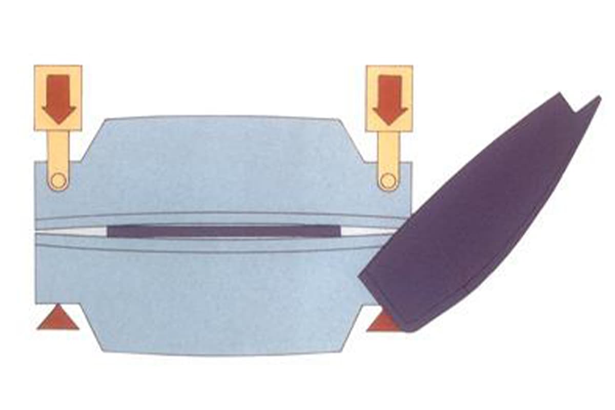
The crux lies in a misunderstanding of air bending, the most commonly used method. In air bending, the part contacts the punch tip and the two shoulders of the die, forming naturally inside the V-opening. The resulting inside radius is determined primarily by the V-opening width, not the punch radius.
Its empirical formula is:
Inside radius ≈ 15–17% of V-opening width.

2)Material Springback
Springback affects not only the angle but also increases the radius after unloading.
(3) Solutions
1)Knowledge Sharing and Training
Operators and process engineers must fully understand how different bending methods influence radius formation:
| Bending Method | Description |
|---|---|
| Air Bending | Radius is determined by V-opening width; high flexibility; low tonnage requirement. |
| Bottom Bending | Punch lightly presses sheet to die bottom; radius determined by punch radius; less springback; higher precision. |
| Coining | Punch fully stamps into material at high pressure, precisely replicating punch radius; nearly no springback, but causes higher wear on machine and tooling. |
2)Precision Control
If the design specifies a strict inside radius (e.g., R2), avoid using air bending. Opt for bottom bending with a punch radius slightly smaller than the target (e.g., R1.8 or R1.9) to compensate for minimal springback.
3)Tool Selection
When air bending is necessary, choose V-dies with carefully calculated opening widths to indirectly control and closely match the required inside radius.
7. Problem Seven: Bend Line Misalignment and Twisting
This issue disrupts the part’s overall geometry—a basic error with serious consequences.
(1) Symptom Identification
The bend line is not parallel to the reference edge, leading to uneven flange widths at each end, or the entire part becomes warped after bending.
(2) Root Cause Analysis
The root cause is uneven force application or loss of reference alignment.
1)Tool Installation
The centerlines of the upper and lower dies are misaligned, causing eccentric bending forces; or die fasteners are loose, allowing movement during processing.
2)Uneven Force Distribution
The operator positions the workpiece askew, or part geometry causes its center of gravity to be offset from the die center, creating imbalanced loads on the ram’s hydraulic cylinders.
3)Machine Accuracy
The parallelism between the ram and bed is out of tolerance, causing the ram itself to descend at an angle.
(2) Solutions
1)Precise Tool Alignment
Strictly follow standard tooling installation and alignment procedures. Use a laser alignment device or simple scribed alignment block to ensure the upper and lower die centerlines coincide along their entire length.
2)Auxiliary Positioning
For large or irregular parts, use front support arms or side locating stops to ensure the workpiece is correctly and stably positioned before bending begins.
3)Machine Inspection
Schedule regular (at least annual) inspections by qualified service engineers using precision instruments such as laser interferometers to check and calibrate the machine’s geometric accuracy, especially the ram-to-bed parallelism.
8. Abnormal Tool Wear and Reduced Service Life

Tooling is a costly asset, and premature damage directly erodes profitability.
(1) Symptom Identification
Tooling—especially punch tips and die shoulders—exhibits severe wear, chipping, or deformation well before its expected lifespan, leading to a consistent decline in product quality.
(2) Root Cause Analysis
This is typically due to “metal-on-metal” abuse or overwork.
1)Improper Matching
- Hardness mismatch: Using untreated standard tooling to bend stainless or high-strength steel is like hitting stone with wood—the tool will degrade rapidly. Shape mismatch:
- Using sharp-corner tooling for thick plates concentrates excessive stress on the punch tip, causing chipping.
2)Overloading Pressure
Setting bending tonnage purely on experience—well above what’s required—forces tooling to operate continually at its stress limits.
3)Lack of Lubrication
When processing certain materials—such as thick plate or high-strength steel—the absence of proper lubrication can cause severe friction and wear between the die and the workpiece.
(3) Solutions
1)Strategic Material Selection and Investment
Choose high-quality dies treated with through-hardening (hardness typically HRC 48–52 or higher) or even surface coatings (such as TiN, CrN), specifically tailored to the primary materials you process. For high-strength materials, always use dies engineered for such applications.
2)Strict Adherence to Tonnage Calculations
Avoid relying on instinct to set pressure. Use the bending force formula or the machine’s built-in calculator to determine the exact minimum tonnage required based on material type, thickness, bend length, and V-die width. Then add a reasonable safety margin, typically 10–15%.
3)Standardized Maintenance Procedures
Implement a full lifecycle management system for dies. This includes pre-storage inspection and rust prevention, in-use cleaning and timely lubrication, and post-use cleaning, inspection, and documented storage. Treat dies as precision instruments, not just blocks of metal.
Ⅳ. Troubleshooting Checklist for Common Press Brake Problems
| Problem | Checklist |
| UnevenBending | - Check if the punch and die are aligned. - Inspect the punch and die for wear or damage. - Ensure the material is correctly positioned against the back gauge. -Verify the press brake alignment to ensure there is no offset. -Calibrate the machine to ensure accurate settings. |
| Springback | - Check if the bend angle is appropriately increased to compensate for springback. - Ensure the inside bend radius is small enough. - Consider heat treating the material to reduce springback. - Verify that the material used is suitable for bending and has low springback characteristics. |
| Over-bending or Under-bending | - Calibrate the press brake settings to ensure metal bending accuracy. - Check if the tooling and material thickness are appropriate for the desired bend. - Regularly inspect and maintain the tooling to prevent wear. |
| Cracking | - Ensure the material used is suitable for bending and within its recommended tensile strength. - Adjust the tooling to reduce stress concentration on the material. - Use proper lubrication to reduce friction and stress during bending. - Consider pre-treating the material to improve its ductility. |
| Surface Imperfections | - Use softer tooling or protective layers on the tooling surfaces. - Regularly clean the tooling to remove any debris or contaminants that could cause scratches or dents. - Inspect the tooling for damage and replace it as necessary. |
| Wrinkling or Folding | - Adjust the punch and die clearance to ensure it is suitable for the material thickness. - Use appropriate tooling to provide adequate support to the material during bending. - Ensure proper material support using back gauges or support arms. |
| Back Gauge Inaccuracy | - Regularly calibrate and maintain the back gauge to ensure it is functioning correctly. - Verify the sensors and mechanical components for accuracy of the bend and replace any faulty parts. - Use advanced backgauge systems with programmable settings to improve precision. |
| Tool Chipping or Breakage | - Use high-quality toling that is appropriate for the material being bent. - Regularly inspect the tooling for signs of wear or damage and repair or replace it promptly. - Properly maintain the tooling and use the correct settings for the material. |
Ⅴ. Material-Specific Challenges
1. Behavior of Different Materials
Understanding the unique characteristics of different materials during the bending process is crucial for optimizing manufacturing operations.
(1) Stainless Steel
- Characteristics: Stainless steel's corrosion resistance and strength make it suitable for construction, automotive, and aerospace. Its yield strength leads to springback during bending.
- Bending Behavior: High strength requires more force and causes springback. Overbending achieves the desired angle.
- Solutions: Use precise tools, larger V-die openings, and higher force. Preheating can reduce cracking risk.
(2) Aluminum
- Characteristics: Aluminum is ductile, corrosion-resistant, and used in industry. Alloys vary in strength and formability.
- Bending Behavior: Aluminum thickness changes during bending.
- Solutions: Choose suitable alloy and temper, apply heat treatment, and use simulation for tool selection.
(3)High-Strength Steel
- Characteristics: High-strength steel gains strength through grain refinement and hardening but has less formability. These steels harden during bending.
- Bending Behavior: More force is needed for bending, with a higher risk of cracking. Mechanical properties can affect bend angles.
- Solutions: Use precise tools, larger V-die openings, and higher force. Preheating can reduce cracking risk. Use finite element analysis (FEA) for stress prediction.
2. Solutions for Material-Specific Issues
(1) Adjusting Bend Radii: Select appropriate bend radii based on material characteristics to minimize stress concentration and cracking risk. For instance, stainless steel typically requires larger inner bend radii, while aluminum can use smaller radii.
(2) Using Specialized Tooling: Choose suitable tooling types for specific materials, such as polymer tools to prevent surface scratches on aluminum or rotary bending tools for complex geometries.
(3) Simulation Software Application: Employ CAD/CAM software for design and simulation to optimize tooling paths and predict potential issues. This approach enhances the reliability of the bending process and ensures that the final product meets design specifications.
Ⅵ. Building a Long-Term Quality Assurance System
1. The Ultimate Weapon: Preventive Maintenance Checklist
In manufacturing, the greatest threat isn’t sudden breakdowns, but the slow, almost imperceptible decline in precision. A press brake producing in-spec parts today could—due to just 0.01 mm of wear on the slide guide—scrap an entire batch next week. Preventive Maintenance (PM) is the ultimate defense against this "precision entropy." It’s not optional extra work; it’s the core discipline for ensuring production stability.
An effective PM system must be tiered, actionable, and accountable. It transforms scattered experience into standardized procedures—replacing the vague “I think it’s time to service” with the firm directive of “This must be checked today.” Below is a ready-to-implement three-tier maintenance framework:
(1) Daily Checks (Operator – 5 minutes before each shift)
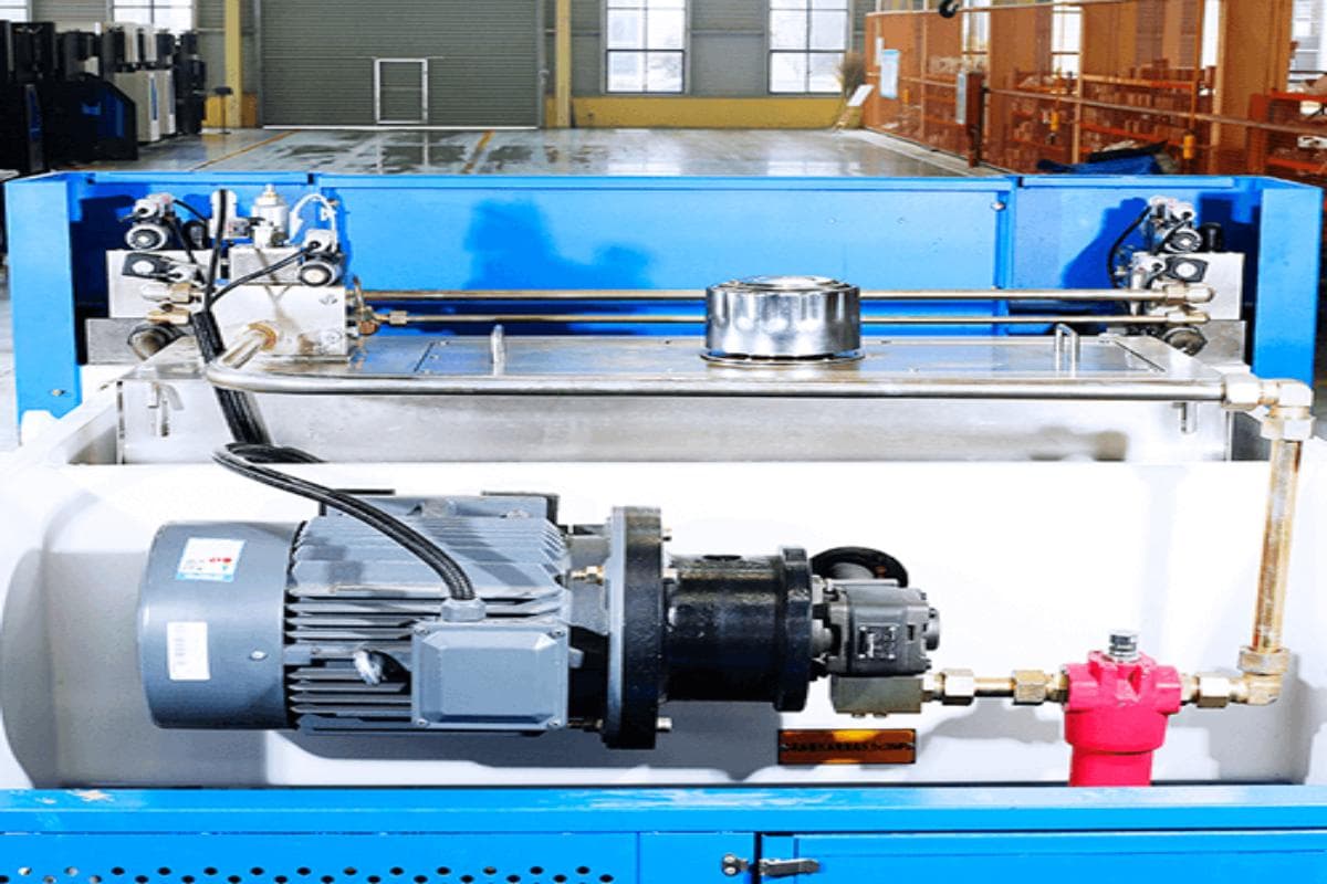
- Hydraulic System: Check oil level is within the normal range and look for visible leaks.
- Dies & Worktable: Use compressed air and a soft cloth to thoroughly clean the upper and lower dies, worktable surface, and back-gauge fingers, removing metal shavings and oil.
- Safety Systems: Test the safety light curtain, emergency stop button, and foot switch to ensure they respond instantly—this is the highest respect for human life.
(2) Weekly Checks (Technician/Team Leader – scheduled weekly)
- Back Gauge Accuracy: Use calibration blocks or calipers to verify the X-axis actual position matches the system display, and check its repeat positioning accuracy.
- Die Clamping: Ensure all upper and lower die clamping devices are secure and show no signs of loosening.
- Guideways & Lubrication: Inspect lubrication of the slide guideways, replenishing or replacing grease/oil according to equipment specifications.
(3) Monthly/Quarterly Checks (Engineer/Professional Maintenance)
- Oil Analysis: Collect a hydraulic oil sample for testing and assess its cleanliness, viscosity, and moisture content to anticipate potential wear on hydraulic components.
- Geometric Accuracy Check: Using precision measuring tools (such as a dial indicator), measure the parallelism and perpendicularity between the ram and the worktable—this forms the foundation for consistent bend angles along the entire length.
- Deflection Compensation System: Functionally verify whether the mechanical or hydraulic deflection compensation system responds with precision and smoothness.
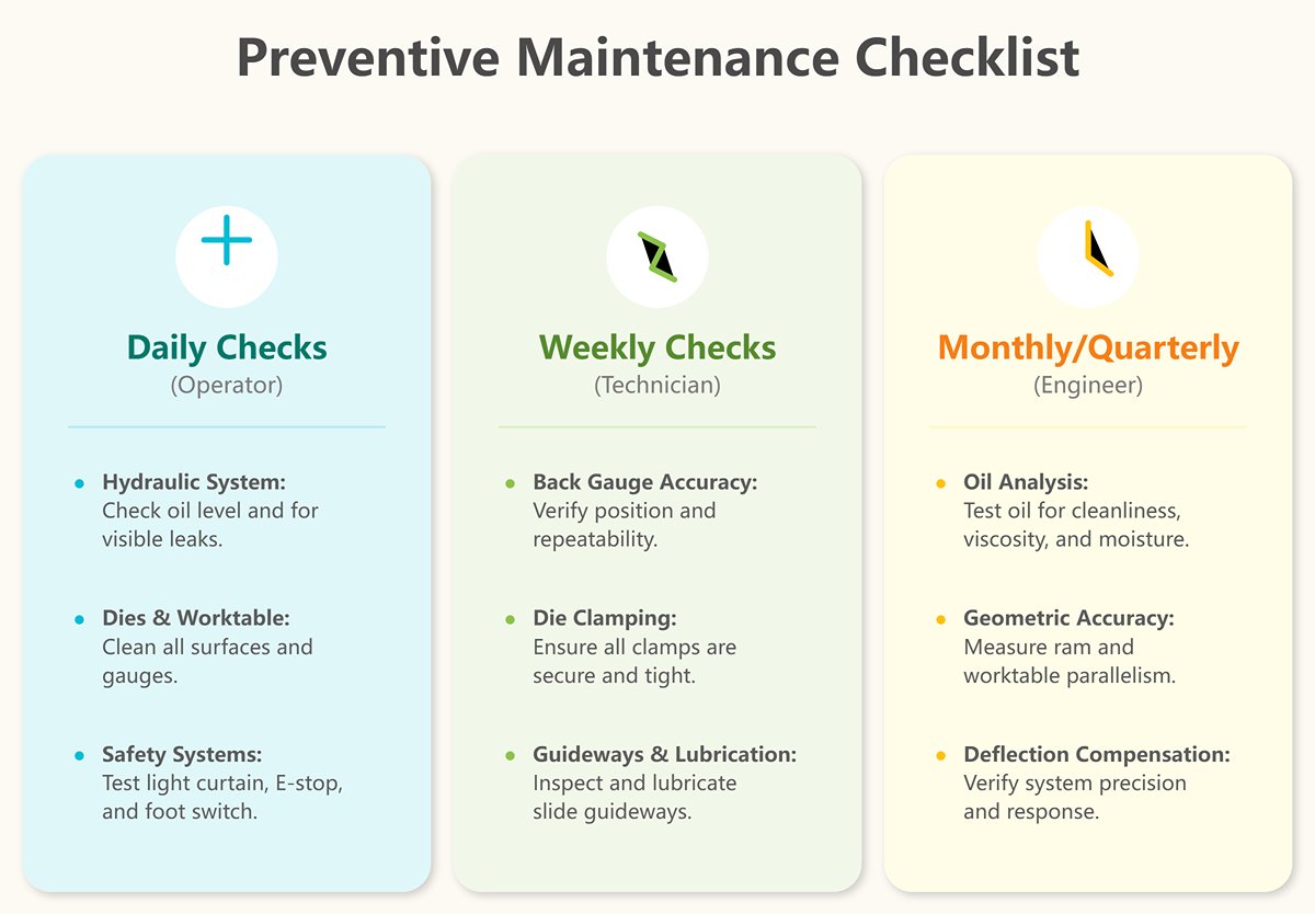
The value of this checklist lies not in its complexity, but in its consistency. Print it out, establish it as a standard procedure, and make maintenance an ingrained part of the organization’s culture—no longer dependent on the memory of a single veteran operator.
2. Strategic Tooling Management
Many managers view press brake tooling as consumables; top-tier manufacturers regard them as core production assets just as vital as the machine itself. A precision die set worth tens of thousands can be rendered useless by careless handling, leading not only to the cost of the tool but also to production downtime and product quality issues. Underestimating tooling is one of the most expensive "hidden costs" in the workshop.
Elevating tooling from mere “tools” to valuable “assets” calls for a comprehensive lifecycle management system:
(1) Create a Tooling Storage System
Say goodbye to the inefficient "treasure hunt" in the workshop corner.
1)Standardized Storage
Design dedicated tool cabinets where each die set (upper and lower) has a clearly labeled, exclusive “home.” Organize by type, size, and radius, enabling visual management.
2)Digital Cataloging
Maintain an electronic ledger documenting each die set’s model, purchase date, material hardness, compatible machines, and current status (new, in use, pending regrind, retired).
3)Status Tracking and Circulation
Implement a sign-out and return protocol. Dies must be cleaned and inspected upon return, and any damage recorded with responsibility assigned.
(2) Invest in Precision-Ground Dies
This is not a cost—it is an investment in efficiency and accuracy.
Boost changeover efficiency: Precision-ground dies ensure extreme dimensional consistency, allowing segmented use without re-alignment, slashing tool change time from tens of minutes to just a few.
Ensure accuracy and interchangeability: A uniform height and centerline guarantee perfect alignment in any position or combination, eliminating bend-line deviation stemming from installation errors.
(3) Implement Intelligent Tool Life Prediction
Shift from reactive replacement to proactive maintenance.
Add usage counters: Track a die’s cumulative strokes or total tonnage in the tooling ledger.
Build wear models: Use historical data to establish wear curves for different dies when processing specific materials, predicting optimal regrind or replacement schedules to prevent large-scale quality defects from overused tooling.

3. Mastering Material Characteristics
We return to the final and most variable point in the “Golden Triangle” — the material.
Machines can be calibrated, and tools can be managed, but each batch of steel sheet has its own “temperament.” A true bending expert—much like a seasoned horse trainer—can sense and adapt to subtle changes in the material. This capability should not rely solely on individual experience but be captured as the organization’s collective knowledge.
(1) Build a Company-Wide Material Parameter Database
This is your most valuable process data asset. Don’t settle for the theoretical yield and tensile strength listed on the material certificate. For each new batch of commonly used material, take random hardness readings with a hardness tester and precisely measure thickness with calipers (measure multiple points and calculate the average).
(2) Record Springback Data
This is the heart of the matter. Whenever you successfully set up a part to meet quality requirements, immediately record the material batch, actual thickness, V-die opening width, and the final CNC angle compensation value. Over time, you’ll build a “springback codebook” customized to your own material supply chain—something no competitor can replicate.
(3) Develop the Habit of Identifying Rolling Direction
Make this as important as reading a technical drawing. During blanking, clearly mark the rolling direction on the sheet with a marker.
Before bending, operators must verify the relationship between the bend line and rolling direction—especially for small bend radii or materials with low ductility. Bending perpendicular to the grain should be treated as an absolute rule.
Fully understand the material’s minimum bend radius and move quality control upstream to the design phase. Establish a feedback loop with the design department, providing a recommended minimum safe bend radius table based on actual shop capabilities for different materials and thicknesses. Preventing “physically impossible” designs at the source is the most effective cost control.
Ⅶ. FAQs
1. What causes uneven bending in press brake operations?
Causes of uneven bending in press brake operations include worn die tips, uneven force, and incorrect height settings. Ensure die tips are in good condition, apply uniform force, and maintain a consistent gap between dies. Regular inspection and maintenance are essential.
2. How can I prevent surface damage to workpieces during bending?
To prevent surface damage during bending, use shape bending methods (air bending, bottom bending, and coining) and increase top plate pressure to minimize friction. Regularly inspect and maintain tooling for proper alignment. Use protective layers like films between the tool and sheet metal.
Keep workspace and tools clean, use proper lubrication, and adjust bending parameters like pressure and bend radius. Ensure proper calibration of press brake settings to maintain consistent pressure.
3. How do I select the right material for press brake bending?
Select material for press brake bending by considering thickness and type, as they impact tooling and bending parameters. Thicker materials need broader dies; thinner ones need precise dies. Understand bending properties, as materials like stainless steel and aluminum behave differently.
Ensure suitable tensile strength to avoid defects. Select proper tooling for bending radius, angle, and pressing force. Regular machine maintenance ensures quality.
4. What are the common mechanical failures in press brake machines and their solutions?
Common mechanical failures in modern press brake machines include hydraulic issues like oil leaks, pump problems, blocked lines, and valve malfunctions. Solutions involve checking seals, maintaining hydraulic oil, ensuring proper pressure, and fixing valves.
Alignment issues like ram and guide rail problems can be addressed by lubrication and correct alignment. Electrical failures like loose connections or faulty sensors need tightening and replacement. Tooling problems and overheating can be mitigated by inspecting tooling and maintaining the cooling system. Regular maintenance and repairs are essential for performance.
5. What are the best practices for maintaining a press brake machine?
To maintain a sheet metal machine effectively, follow these practices:
Regularly clean the machine and work area to remove dirt, metal particles, oil, and dust that cause jamming and wear. Lubricate mechanical parts, guide rails, back gauges, axes, and ball screws to reduce friction. Automated systems ensure consistent lubrication.
Inspect moving parts, hydraulic hoses, and electrical connections for wear or damage. Listen for unusual noises indicating issues. Calibrate and align the machine. Ensure the back gauge is calibrated and parallel to the beam. Verify tooling system locks tightly.
Address pressure issues promptly. Check for a stuck orifice or electrical faults, clean the orifice, and inspect the wiring. Prevent jamming by keeping setups clean and lubricated to avoid trapped particles.
Choose the correct bend radius to avoid stress on the tool, preventing breakage and incorrect dimensions. Perform safety checks. Verify safety guards and test emergency stop buttons and sensors. Disconnect from the main supply during maintenance and ensure the machine is stationary before accessing parts.
Ⅷ. Conclusion
We have discussed some press brake bending problems and press brake troubleshooting common solutions. Many issues can arise with press brake machines, and not all of them can be listed here. If you require further information, please feel free to contact us for more detailed answers.
My company, ADH Machine Tool is a professional sheet metal manufacturer that has produced hydraulic press brakes, shears, and fiber laser cutting machines for over 40 years. Proper maintenance is crucial for a press brake's efficient use and prolonged service life.


