I. Introduction
This blog is a comprehensive guide of press brake (sheet metal bending machine) manual that introduces the operation procedures of a press brake. Whether you're a seasoned operator or a newcomer eager to master its intricacies, understanding press brake operation is essential. The following is a brief introduction to the machine. For those who want to understand bending fundamentals in more depth, explore our Guide to Press Brake Bending for practical techniques and examples.
1. Structure and Working Principle
The basic principle of brake forming relies on force, otherwise known as tonnage. The higher tonnage, the thicker the materials that can be bent and vice versa. Along with the tonnage comes bending length, which is the maximum length of sheet metal that can be bent.
The press brake is one such tool that is capable of bending even the largest sheet metal, making it an indispensable and critical piece of equipment in the sheet metal forming and shaping process.
The press brake tooling is known as upper punch and bottom of the die. It bends the sheet metal through the upper and lower dies at the ram. Different die and punch can produce profiles with different angles and shapes.
There are oil cylinders on the left and right uprights that respectively drive the movement of the ram. The ram moves downward during operation, exerting pressure on the press brake metal sheet against the die.
The stroke of the ram is controlled by the hydraulic and electrical systems. The body of the press brake is composed of two vertical steel plate structures. The oil cylinders and hydraulic and electrical control systems ensure the accuracy of repeated bending. There is also a workbench at the bottom of the press brake.
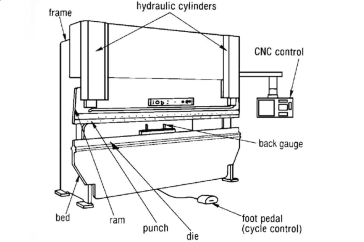
To prevent the workbench and ram from deformation due to long-term overload, the hydraulic press brake is equipped with a crowning device that can compensate for the deflection of the workbench and ram.
The bending process starts with the metal sheet freely placed on the bottom die. As the top die applies pressure, the bending force arm and radius of curvature decrease, causing the plate to conform to the V-groove of the lower die. At the end of the stroke, the upper and lower form a V-shaped die, completing the bend. For a deeper understanding of how to properly set up your machine before operation, you can refer to the Complete Guide to Press Brake Installation.
For operators looking to achieve precise control and automation, understanding how to select the right controller is essential — see our Guide to Press Brake Controller Selection for detailed insights.
2. Type of Press Brake
You’ll need to know that the common types of press brakes are mechanical press brakes, manual press brakes, hydraulic press brakes, Servo-electric, or CNC (Computer Numerical Control) press brakes. Fast forward, modern press brakes have evolved into high-tech machines that use computer technology and hydraulic system principles. For a more in-depth exploration of how digital control enhances bending precision, check out the Press Braking and CNC Technology Guide.
CNC press brake utilizes modern computer technology to improve accuracy and efficiency and is equipped with a CNC controller to proceed with complex bending operations.
Hydraulic press brakes stand out in the metal fabrication industry for their versatility and precision. Hydraulic system offers controllable and consistent bending force, which reduces manual labor. For a broader understanding of hydraulic cutting and forming principles, you can also refer to the Guide to Hydraulic Shearing Machines for practical insights into hydraulic systems in sheet metal processing.
3. Bending Methods
The material and opening of the die should be selected according to the workpiece and press brake bending method. Bending techniques such as air bending, coining, and bottom bending each have their place in machine operation.
In air bending, choosing a narrower die angle allows you to increase the depth of penetration to account for springback, which is the tendency of the sheet metal to spring open slightly after the punch releases bending pressure. Harder materials exhibit more springback, while softer materials conform more easily to the die’s angle.
Techniques like coining can offer precise bending, compensating for springback without resorting to bottom bending. In bottoming, the punch tip radius determines the inside bend radius, and the die angle determines your bend angle. The distance of that straight line is the radius.
In the ever-changing manufacturing industry, using a press brake to bend a piece of sheet metal is a common metal forming method used to create finished products from metal materials. The press brake machine is designed for bending plate and sheet material, which is widely used in various industries, including household industries, construction, machinery, automobile, aviation, and others. A deeper technical explanation of bending behavior and crowning compensation can be found in Understanding Press Brake Metal Bending.
II. Principles and Mechanisms Module
1. The Physics of Metal Bending
Every bend is a precise dance of material mechanics unfolding at the microscopic level. Master its three core elements, and you hold the key to decoding any bending phenomenon.
(1) Plastic Deformation
Picture gently bending a paperclip—when you let go, it springs back to its original form. That’s elastic deformation. But if you force it into a sharp angle, the shape changes permanently—this is plastic deformation.
The essence of a press brake’s work is to apply sufficient force to push sheet metal beyond its “elastic limit” into the plastic deformation zone, achieving the desired permanent shape.
(2) Springback
Springback is one of the biggest challenges in bending—and a major factor separating novices from experts. Even after plastic deformation, metal retains some elastic energy. Like a compressed spring, once the tooling pressure is released, that stored elasticity will try to push the workpiece partway back, making the final angle smaller than intended.
For example, to end with a perfect 90° angle, you might actually program the bend to 88°. The key insight: springback is not an error, but an inherent property of the material. Mastery of bending largely comes down to accurately predicting and compensating for it.
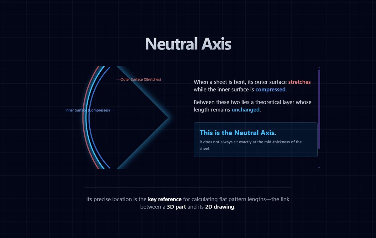
(3) Neutral Axis
When a sheet is bent, its outer surface stretches while the inner surface is compressed. Between these two lies a theoretical layer whose length remains unchanged—this is the neutral axis. It does not always sit exactly at the mid-thickness of the sheet.
The neutral axis is the reference line for calculating flat pattern lengths. Its precise location is the key link between a 3D finished part and its 2D engineering drawing.
2. Key Parameters
The numbers flashing on a CNC control screen are not random—they are the mathematical expressions of physical principles, closely interconnected.
(1) Tonnage
This is not the weight of the machine, but the maximum pressing force the ram can exert. The required tonnage is not “the higher the better,” but must be precisely calculated. It depends on factors such as the material’s tensile strength, sheet thickness, bend length, and the V-die opening width. Incorrect tonnage can at best cause bending failure, and at worst permanently damage tooling or the press brake itself.
(2) Stroke
This is the distance the ram travels downward. In the common “air bending” method, bend angles are determined entirely by how far the ram descends—the deeper it goes, the smaller the angle. Modern CNC systems achieve high precision by controlling stroke depth to within microns.
(3) Bend Radius
Typically refers to the inside corner radius of the bend. It is primarily determined by the tip radius (nose radius) of the punch, but material properties and V-die opening size also play a role. A common misconception is that the inside radius exactly matches the punch tip radius—in reality, due to springback and material flow, it is usually slightly larger.
(4) K-Factor and Bend Compensation
These are advanced essentials—the backbone of accurate sheet metal flat pattern development.
The K-factor is a dimensionless ratio that precisely defines the neutral axis position within the material thickness (K = distance from neutral axis to inside surface ÷ material thickness). It is influenced by factors such as material type, bend radius, and bending method.
Bend allowance/deduction is a calculated value based on the K-factor, used to adjust flat pattern length to account for the material length consumed or stretched during bending.
Without an accurate K-factor, precise flat patterns are impossible—you’ll have sown the seeds of error before the first process (laser cutting or punching) even begins. For professionals looking to master this crucial calculation, we offer detailed guides and resources on K-Factor Bend Allowance and Bend Deduction Precise Solutions.
3. Influence of Material Properties
Think of different metals as having distinct personalities—treat them all the same way, and the results will vary widely.
(1) Carbon Steel
The most common material—like a “model student,” its bending behavior closely aligns with theoretical predictions. It has relatively small and predictable springback, making it the ideal baseline for parameter setup.
(2) Stainless Steel
A “tough and stubborn” character. Its higher strength and hardness require greater tonnage. More importantly, it work-hardens significantly during bending, and its springback is 2–3 times that of carbon steel. Programming for stainless must include substantially greater springback compensation.
(3) Aluminum Alloys
A “sensitive artist.” Softer and more ductile, but easily scratched, requiring scratch-free tooling or surface protection. Certain hard alloys (like aerospace-grade aluminum) can crack if bent with too small a radius, and bend orientation relative to the grain matters—bending along the grain carries far higher crack risk than across it.
4. Clarifying Common Misconceptions
On the path to mastery, the greatest obstacles are often the false beliefs deeply ingrained in our thinking.
(1) Myth One: “Experience is everything—Theory is useless.”
Experience is invaluable, but only when built on an understanding of underlying principles. Pure experience allows you to repeat yesterday’s success, but not to adapt to today’s changes—new materials, new tooling, new specifications.
Principles + Experience = Expertise. This combination ensures you know not only how to do something, but why—giving you the power to solve unfamiliar problems.
(2) Myth Two: “I have a universal parameter sheet—just input the numbers.”
Blindly copying parameters is the biggest gamble in production. Even within the same material grade, mechanical properties vary slightly between batches. Tooling wears, and factors like hydraulic oil temperature can affect ram positioning accuracy. These variables can make copied parameters unreliable.
The true best practice is to use principles to build—and continuously refine—your own parameter database, tailored to your machines, your tooling, and your materials.
At this point, you’ve grasped the core logic behind bending. This mental framework will be your strongest weapon in tackling all practical challenges ahead. Next, we’ll carry these principles into the stage of real-world preparation.
Ⅲ. Installation of Press Brake
1. Choosing the Right Location
- Location Selection: Ensure the press brake is placed in a sufficiently large area to allow the press brake operator to move freely. The press brake operators need to know that the area should be equipped with appropriate power supply and ventilation systems.
- Level Ground: Use a level to ensure the ground is flat to prevent the machine from moving during operation.
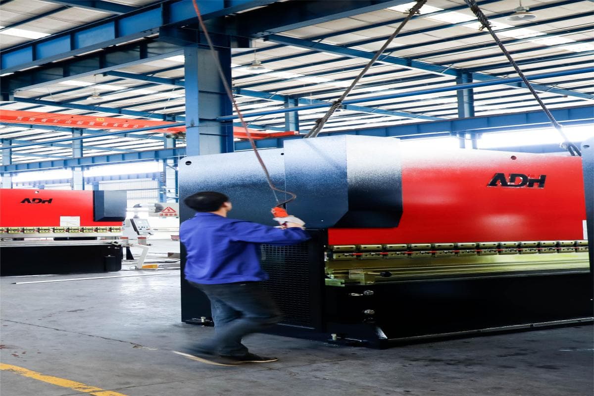
2. Using a Crane
- As the press brake is a large machine, it needs a crane to lift the press brake for unloading and transportation. The rope of the crane should be strong enough and long enough to ensure the safe lifting of the every press brake.
- Fix the chain on the front lifting hole of the machine. Use a crane with a safety device to lift the press brake. It is loaded on the truck and then transported to the installation site for installation.
3. Installing the Machine
(1) Machine Leveling

In order to ensure the bending accuracy of the press brake, the press brake bending needs to be leveled regularly. Place the press brake on the horizontal ground and place the spirit level on A1 and A2 to test its levelness, respectively. A deviation of 1-2 mm per meter is allowed. If the difference is too large, the leveling bolts at the bottom of the press brake need to be adjusted.
(2) The Connections of Electric
It's recommended to have professionals check the electrical wiring of the press brake and connect the power supply. The electrical connection of the three-phase system should be in the correct position. When connecting the press brake to the three-phase power supply, ensure the direction of the pump rotation drive motor is correct.
If the motor turns incorrectly, the phase of the inlet circuit needs to be changed, but the internal circuit cannot be changed. Afterward, restart the oil pump motor and check the steering. Before checking the rotation direction of the motor, ensure that the press brake has been cleaned and leveled.
(3) Hydraulic System
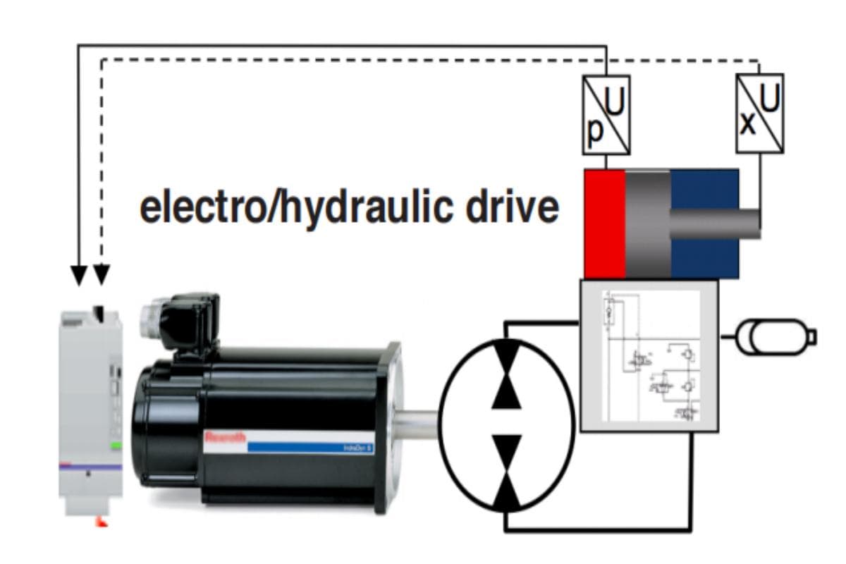
In the hydraulic drive system of a press brake, the AC servo motor moves the ram and aligns the hydraulic oil with the variable speed pump. The driving device is installed on the beam and connected to the machine body via the guide rail. The press brake control system controls the position of the beam and moves it up and down through the drive motor.
Grating rulers on both sides of the press brake read the signal and provide feedback to the control system. The control circuit, filling valve, and servo valve in the oil cylinder are independent and controlled by the DNC controller. A hydraulic or electro-hydraulic servo system can improve bending accuracy and reduce energy consumption and cost.
To maintain the cleanliness of the hydraulic system, keeping the oil tank and hydraulic oil clean is crucial. When changing hydraulic oil, wipe the inside of the oil tank with a soft towel, clean the oil tank with clean gasoline, open the valve storing the dirty oil, drain it, and wipe off stains on the oil tank's surface.
The hydraulic oil of the press brake should not be used at too low or too high a temperature. If the temperature is below zero or above 70 degrees, an oil heater or cooler can be installed. Fill hydraulic oil through the air filter and operate a press brake to discharge the bubbles in the hydraulic circuit after filling.
(4) Back Gauge of Press Brake
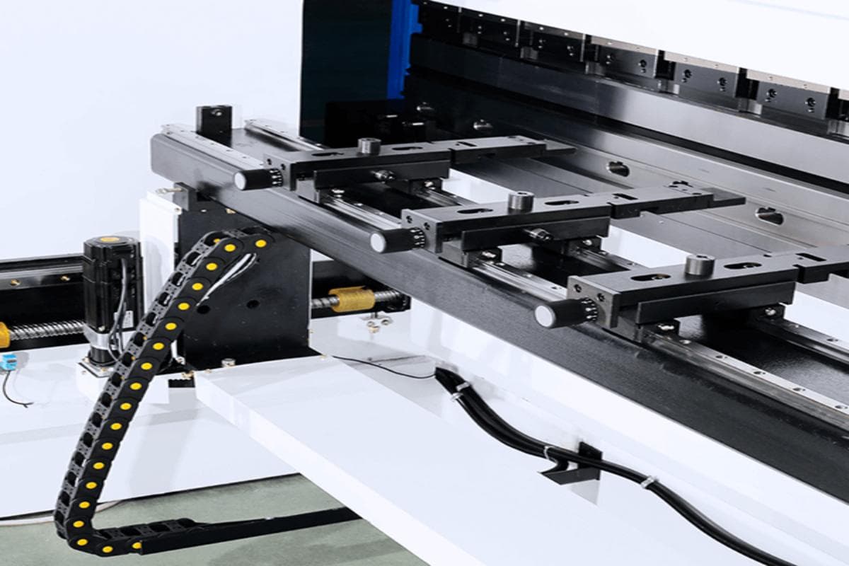
The back gauge of a press brake is used for positioning the workpiece. To position the workpiece, place it on the lower die and push it into the machine, and the stopper finger of the back gauge will dock with the workpiece. The back gauge's axes can move in different directions via the control system.
The X-axis can move forward and backward, the R-axis can move up and down, and the Z-axis can move left and right. Each axis of the back gauge is driven by an independent motor. The Z-axis and R-axis can also be adjusted manually but only from the back of the machine.
The linear guide rail and ball screw enable the axes of the back gauge to move freely. The back gauge moves in the X-axis direction, and the force is limited to 150N to prevent collisions.
Ⅳ. Press Brake Operation Basics
1. Pre-Operation Checks
(1) Inspecting the Equipment
Visual Inspection: Check the electrical system to see whether the switch, control, motor, and grounding are in normal working condition. Verify the oil level in the oil tank and the hydraulic system's condition. Idle the machine and maximize the press brake stroke. Check whether the machine is operating normally, the motor's rotation is normal, and the sound is normal.
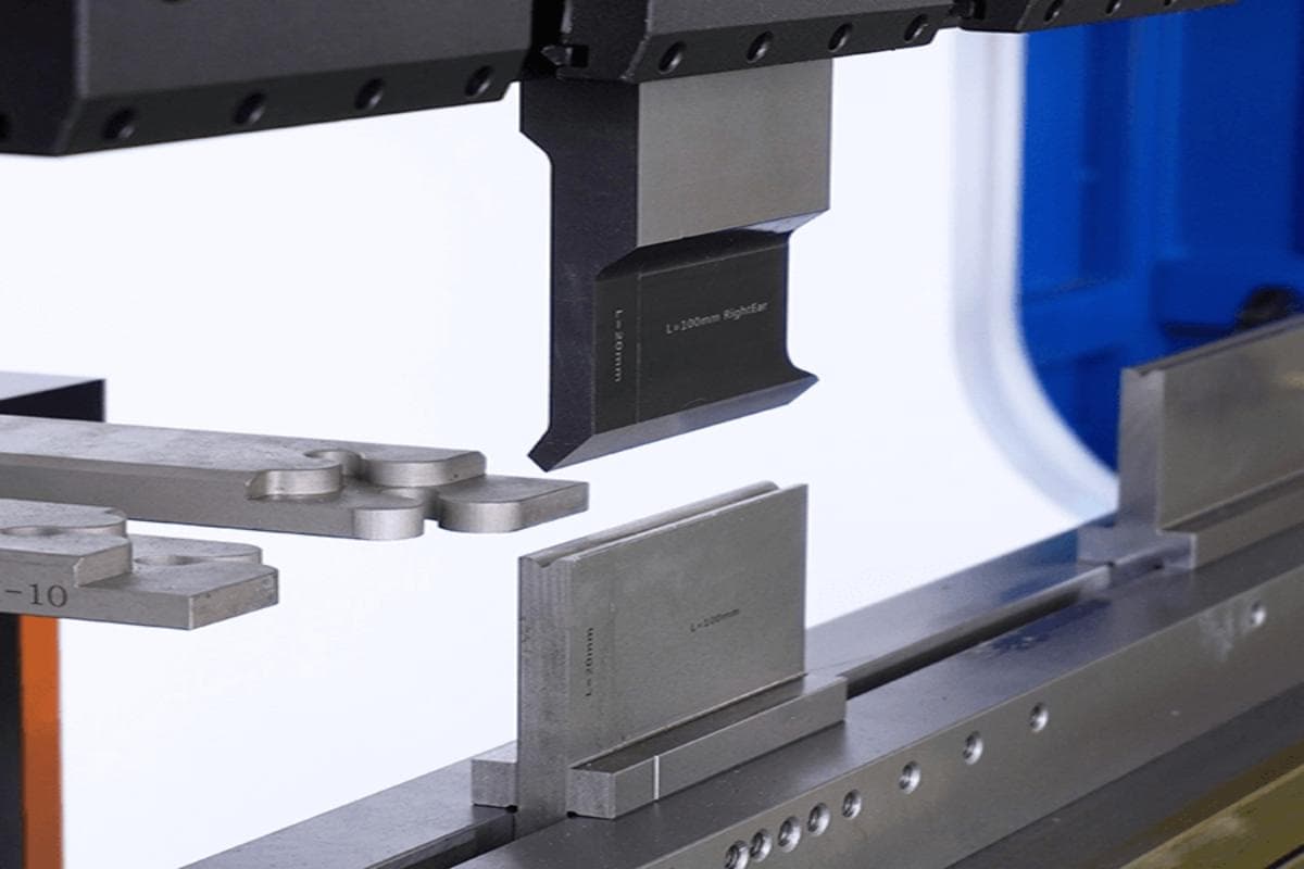
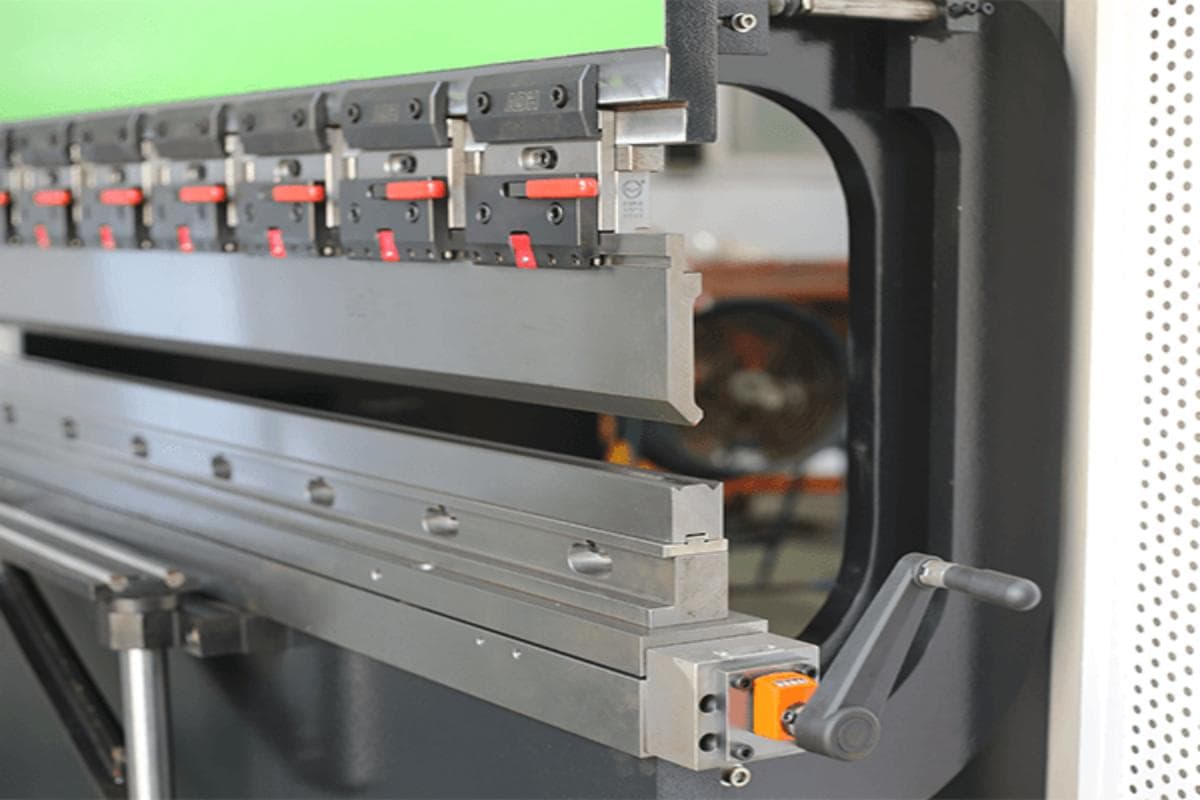
Tooling assembly and alignment: Before installing the punch and die set, stop the machine, and install the lower and upper dies. The upper and lower dies of the press brake must be aligned to obtain higher bending accuracy. To align the upper and lower dies, drive the ram downward, bringing the upper dies close to the lower dies, leaving a distance equal to the workpiece thickness. Manually adjust the upper and lower die positions using the lower die bolts and upper die clamps. After aligning the upper and lower dies, drive the ram upward.
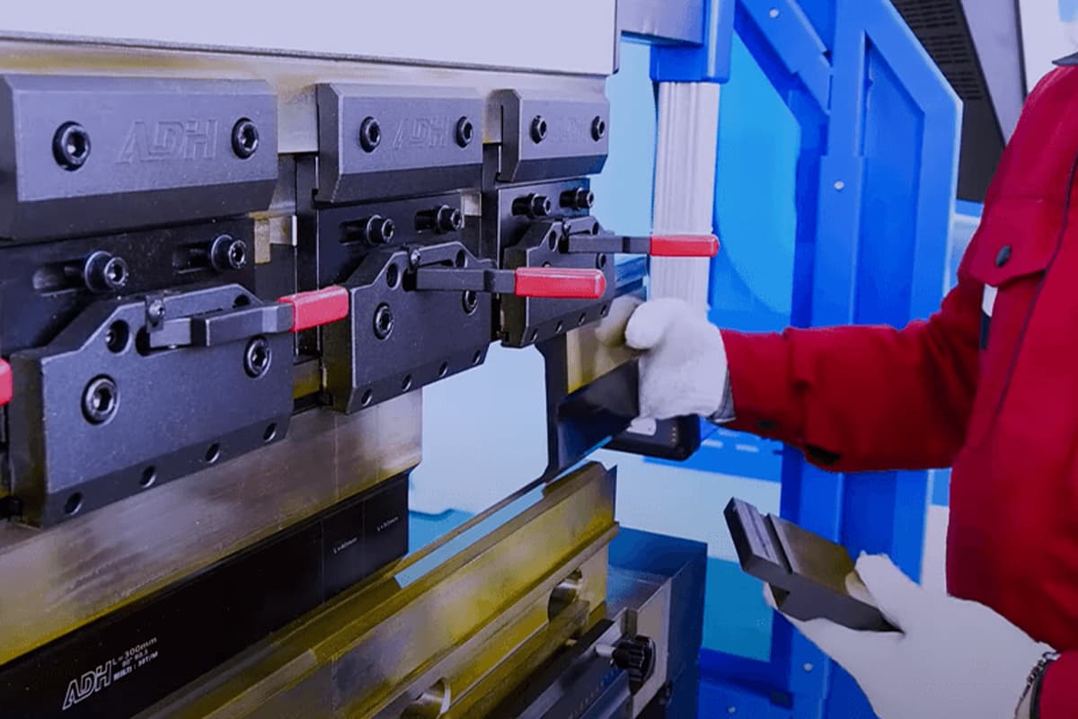
(2) Safety Equipment
- Safety Devices: Ensure all safety devices (such as light curtains and emergency stop buttons) are functioning properly.
- Personal Protective Equipment: Operators should know to wear appropriate personal protective equipment (PPE), such as gloves, safety glasses, and steel-toed boots.
(3) Review the Operation Manual
- Understand the machine's capabilities, limitations, and safety features.
- Familiarize yourself with the specific press brake model and its controls.
2. Operation Steps
(1) Setting Up the Machine
- Selecting Tools: Choose the appropriate punch and die based on the required bending angle and material thickness. Inspect tooling for wear or damage; replace if necessary. Ensure tooling is free of cracks or dents.
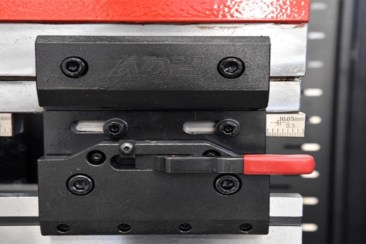
- Install and Align Tooling: Secure tooling onto the press brake bed using clamps or hydraulic clamping systems. Use shims or adapters if required. Align tooling with the back gauge to ensure precision in bending operations.
- Adjusting the Back Gauge: Adjust the position of the back gauge according to the size of the workpiece to ensure accurate positioning.
(2) Programming (for CNC Press Brakes)
- Enter Parameters into Control Panel: Use the software interface to program the bending angle, bending length, and tool parameters.
- Develop Bending Programs: Create sequences for multiple bends using CNC software to optimize precision and minimize errors.
- Test Run: Perform a test run to ensure the machine is working properly and the tools are correctly installed.
(3) Initiating the Bending Process
- Material Placement: Place the metal sheet on the press brake bed, ensuring it is aligned with the back gauge and reference points.
- Activate the Press Brake: Start the machine using foot pedals or control panel commands, allowing the punch to press down on the metal sheet to perform the bending operation. For hydraulic and CNC press brakes, verify that the hydraulic system is pressurized and ready.
(4) Monitoring and Adjustments
- Observe the Bending Process: Lower the ram gradually, allowing the punch to press down on the metal sheet. Apply pressure steadily to achieve the desired bend angle. After the bend is complete, release the pressure and lift the ram. Watch for unusual noises, vibrations, or deviations during bending operations. Stop immediately if issues arise.
- Checking the Bend Angle: Remove the metal sheet and check the bend angle and dimensions to ensure they meet the specifications. Make any necessary adjustments and repeat the process if needed.
(5) Post-Bend Checks
- Inspect Finished Workpieces: Check for defects such as cracks, incorrect angles, or misalignments in bent parts.
- Document Adjustments: Record any changes made during operations to improve future setups and reduce errors.
3. Shut down the machine
When turning off the press brake, switch to manual mode, and lower the ram by stepping on the pedal to align the upper die with the lower die. Press the stop button and turn off the main motor.
The switch parameter should be set to 0. In case of emergencies, press the emergency stop button, but this will not affect the subsequent procedure since only the axes and pump are turned off. Release the button to restart.
Ⅴ. Press Brake Maintenance
Safety Considerations for Press Brake Operation
Operator Protection and Training
Operator safety is crucial when using press brakes. Operators need comprehensive training on machine safety protocols, including:
- Understanding machine hazards: point of operation, nip points, rotating parts, flying chips, and sparks.
- Familiarity with safety features and emergency stop procedures.
- Proper use of personal protective equipment (PPE).
Employers must provide training and enforce strict operating rules to ensure a safe environment.
Safety Features and Equipment
Modern press brakes are equipped with various safety features designed to protect operators:
- Mechanical Guards: Prevent accidental contact with moving parts.
- Light Curtains: Detect operator presence and stop the machine if obstructed.
- Emergency Stop Buttons: Quickly halt the machine during emergencies.
- Two-Handed Controls: Require both hands to operate, keeping hands away from danger.
- Awareness Barriers: Railings, chains, or cables with warning signs to protect from reach-through hazards.
Personal Protective Equipment (PPE)
Operators must wear appropriate PPE, including:
- Safety goggles.
- Gloves.
- Ear protection.
Maintenance Guidelines for Press Brake Operation
Regular Inspections and Maintenance
Regular inspections and maintenance are vital for safe and efficient press brake operation:
- Daily Inspections: Check for loose or damaged parts, leaks, or abnormal noises. Address issues promptly.
- Weekly Inspections: Lubricate moving parts and check hydraulic hoses and connections for damage.
Lubrication and Hydraulic System Maintenance
Proper lubrication and hydraulic maintenance ensure smooth operation and longevity:
- Follow the manufacturer’s guidelines for lubricating guides, bearings, screws, and hydraulic components.
- Check hydraulic systems for leaks, maintain fluid levels, and replace filters regularly.
Electrical System Maintenance
Electrical system maintenance is crucial for safe operation:
- Inspect electrical components, wires, and connections regularly. Keep them clean and free from dust or debris.
- Address any loose connections promptly to prevent electrical issues.
Maintenance Schedules and Manufacturer Guidelines
Follow the manufacturer’s maintenance schedules and guidelines for optimal performance:
- Adhere to the manufacturer’s manual for specific maintenance schedules, recommended lubricants, safety precautions, and troubleshooting tips.
- Maintain the hydraulic oil circuit by verifying oil levels, using the recommended type of hydraulic oil, and changing the oil at specified intervals. Clean the fuel tank during each oil change and maintain an ideal operating temperature.
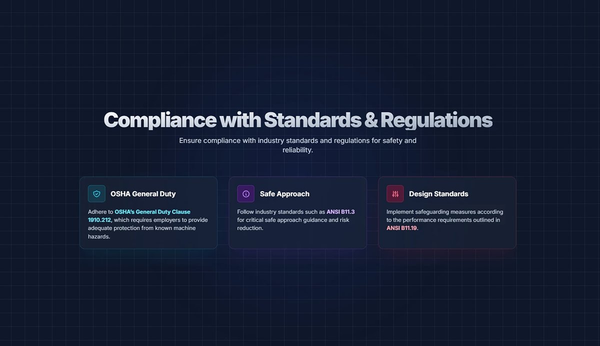
Compliance with Standards and Regulations
Ensure compliance with industry standards and regulations for safety and reliability:
- Adhere to OSHA’s General Duty Clause 1910.212, which requires employers to provide adequate protection from known machine hazards.
- Follow industry standards such as ANSI B11.3 for safe approach guidance and ANSI B11.19 for design standards.
Ⅵ. Advanced Mastery Module
If you can already produce consistent, high‑quality parts, congratulations—you are a dependable, skilled operator. But beyond meeting standards lies excellence; beyond repetition lies creation. This module is your stepping stone to a decisive leap in your career. We will go beyond simply asking “how to do it” and delve into “how to do it better, smarter, and more efficiently.” This is not just a technical upgrade—it’s a transformation in mindset. From this point on, you will learn to think and act like a true master of the craft.
1. Mastering Variables
(1) Springback Behavior Across Materials & Building a Compensation Database
Springback is an inherent property of metal, not a flaw in the process. Your mission is not to eliminate it, but to predict and master it with precision.
1) Build your own “Material DNA Library”:
Never rely blindly on the generic databases supplied with your equipment. True experts build exclusive process databases for every material and thickness used regularly in their plant.
Starting today, use a notebook or spreadsheet to record: material grade + thickness + V‑die opening + punch tip radius → programmed bending angle → actual angle after springback → required compensation value. This tailor‑made, continuously refined dataset will become your most valuable, inimitable core asset.
2) Understand the “temperament” of every material:
| Material | Properties & Processing Recommendations |
|---|---|
| Carbon Steel | “Well‑mannered,” with small, stable springback; ideal as a baseline reference. |
| Stainless Steel | “The tough rebel,” with 2–3× the springback of carbon steel; pronounced work‑hardening effect. Requires overbending to compensate. |
| Aluminum Alloy | “The sensitive aristocrat,” with moderate springback but significant grade‑to‑grade differences (e.g., notable between 5‑series and 6‑series). Database‑driven parameters are essential. |
3) The art of compensation:
Go beyond single‑angle compensation: For high‑precision requirements, simply adjusting one angle may be insufficient. Advanced technicians employ composite techniques—such as the CNC’s “multi‑stage light bending” mode—performing two or three slight bends at the same location to release internal stresses and significantly reduce springback uncertainty.
(2) Mark‑Free Bending Techniques
When working with mirror‑finish brushed stainless steel, brightly coated sheets, or expensive anodized aluminum, any surface mark counts as failure. At that moment, you switch from “mechanical engineer” to “surgeon,” aiming for flawless forming with zero damage.
1) Isolation is the first principle:
Never allow hard steel tooling to come into direct contact with delicate workpiece surfaces.
- Protective film: Ensure any factory‑applied protective film on the bend area remains intact.
- Mark‑free bending pads: Flexible pads made from high‑density polyurethane, placed on the lower die’s V‑opening. Like a tough “soft carpet,” they transfer pressure while cushioning direct contact between tool and workpiece, effectively preventing indentation marks.
2) Select the right “gentle weapon”:
Nylon or polyurethane‑tipped dies incorporate softer, non‑metallic contact surfaces to prevent scratches from the outset.
Rotary dies are an innovative option in which two rotating cylinders replace fixed die shoulders. As the workpiece is pressed in, the contact point rolls rather than slides, minimizing friction—an ultimate solution for truly mark‑free bends.
2. Complex Workpiece Fabrication
With basic bending mastered, you can build the “skeleton.” With advanced techniques, you create “organs” with fine details and multifunctionality.
(1) Hemming
Hemming is like giving a razor‑sharp metal edge a refined “protective cover.” It folds and flattens the sheet edge, dramatically increasing its strength and rigidity, eliminating dangerous burrs, and creating a premium finish.
First, use a sharp‑angle punch (e.g., 30°) to pre‑bend the edge into a tight angle.
Then switch to or use a dedicated hemming die (flat punch with flat lower die) to compress the pre‑bend until fully flattened.
- Common uses: appliance door edges, enclosure cover flanges, automotive panel stiffeners.
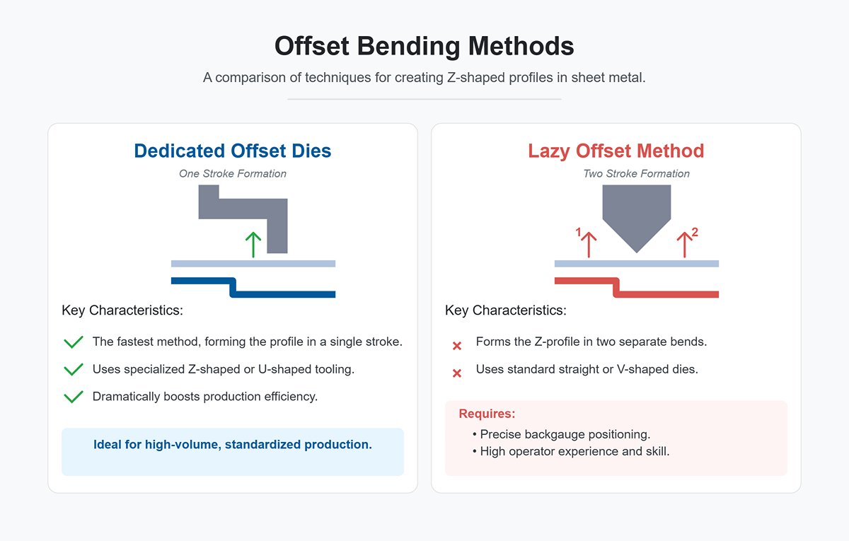
(2) Offset Bends
Offset bending creates a Z‑shaped or step profile in a single stroke, greatly boosting production efficiency.
- Dedicated offset dies: The fastest method—upper and lower tools are shaped in a Z or U profile, completing the form in one slide stroke. Ideal for high‑volume, standardized production.
- The “lazy offset method”: Without dedicated tooling, masters form Z‑profiles using standard straight dies in two separate bends. The key is precise backgauge positioning and anticipating material deformation—a perfect blend of experience and skill.
(3) Multi‑stage Bend Sequence Optimization
When a workpiece requires multiple bends, the sequence is far from arbitrary. A wrong order can cause interference with the press brake, frequent flipping, or unnecessary tool changes—all wasting time.
Optimizing the bend sequence is a strategic “mental chess match” against time.
1) Outside‑to‑inside:
Bend the outer flanges before the inner ones.
2) Short‑to‑long:
Handle short edges first to leave room for bending the longer ones.
3) Group similar operations:
Complete as many bends as possible that use the same tooling and orientation in one run.
4) Anticipate interference:
Before programming or bending, mentally simulate each stage to ensure the part won’t collide with the machine throat, ram, or backgauge.
Modern offline programming software can automatically simulate and suggest the optimal bending sequence, but understanding the underlying logic enables better judgment when unexpected situations arise.
3. Advanced CNC Programming: Pushing the System to Its Limits
The CNC controller is the language between you and the machine. Mastering its “advanced grammar” lets you command intricate, seemingly impossible moves.
(1) Online vs. Offline Programming—Strengths, Trade‑offs, and Strategic Choices
1) Online programming:
Parameters are entered directly at the machine’s control panel. Advantages: intuitive and fast; ideal for simple parts, prototypes, or urgent single‑piece runs. Drawbacks: consumes valuable machine time; for complex parts, programming and debugging can leave the press brake idle for extended periods.
2) Offline programming:
Using specialist software (e.g., SOLIDWORKS, AutoCAD with add‑ons) on a separate computer. Advantages: maximum efficiency—while the machine produces part A, you can program parts B, C, and D in the office.

3) Accuracy and safety:
Software offers 3D simulation to detect all potential collisions and interferences in advance, and can automatically optimize the bend sequence.
4) Handling complexity:
Effortlessly manages parts with dozens of bends. Decision: For modern workshops focusing on efficiency and complex part processing, offline programming is the obvious choice.
(2) Mastering Key Parameters: Backgauge Retraction, Angle Correction, Deflection Compensation
Backgauge retraction:
As the ram descends and the workpiece starts to tilt upward, the backgauge automatically withdraws slightly to avoid colliding with the part. This is an essential function for preventing damage and dimensional errors.
Angle correction:
This is a prime example of the intelligence built into modern CNC systems. Once you measure the angle of the first workpiece and input the actual value, the system automatically performs reverse calculations to adjust the ram’s pressing depth (Y-axis coordinate), delivering precise compensation for the next bend.
Deflection Compensation:
Under heavy tonnage, every press brake experiences a subtle, invisible downward deflection in both the ram and the bed’s center—resembling a slight smile. This results in the angle at the workpiece’s center being greater than at its ends. A deflection compensation system counters this by applying an upward force beneath the bed, ensuring it remains perfectly straight under load. Key insight: Without understanding how to properly set and use deflection compensation, achieving uniform angles on a long workpiece is impossible.
4. Quality and Efficiency Optimization
(1) Application of First Article Inspection (FAI) and Statistical Process Control (SPC)
1) First Article Inspection:
This is not simply measuring the first part—it’s the formal “initial certification” of the entire production process. It requires checking every dimension and tolerance against the drawing, giving the first piece a thorough and comprehensive “health check,” and producing a formal report. Passing the FAI is your declaration: “My full setup—personnel, machine, materials, methods, and environment—has been validated and is ready to consistently produce conforming products.”
2) Statistical Process Control:
If FAI is the birth certificate, SPC is the ongoing health monitoring throughout the product’s life cycle. By regularly sampling workpieces during mass production, measuring them, and plotting the data on control charts, you can clearly visualize process variation. When points begin drifting from the centerline or approaching control limits, it signals that an element—such as tool wear or changes in oil temperature—may be going out of spec. SPC transforms your role from reacting to defective parts to proactively preventing them.
(2) Cycle Time Optimization and Automation Upgrades (e.g., Robotic Loading/Unloading)
1) Cycle Time:
This refers to the total time required to produce a single part. A true expert will break down the cycle time like an F1 pit stop—examining each step: material pick-up, positioning, bending, flipping, unloading—and asking: Which step can be faster? Which motion is unnecessary? By refining bend sequences and eliminating wasted movement, saving even three seconds per part can add up to a massive productivity boost over a full day.
2) Automation Considerations:
When your process is already optimized to the limit, the next step is to delegate repetitive tasks to robots. A robotic bending cell can operate around the clock—7 days a week—with perfectly consistent cycle times and precision.
Ⅶ. FAQs
1. How does a press brake work?
A press brake uses a punch and dies to bend the metal sheets. The metal sheet is placed on the press brake's bed, featuring a V-shaped groove. The ram, carrying the punch, moves down, applying force to the sheet. This force deforms the sheet, shaping it to the die. The backgauge ensures precise positioning. The ram's movement can be controlled mechanically, hydraulically, pneumatically, or electrically.
2. How to select the right tooling for a press brake?
Selecting the right tooling for a press brake involves several critical considerations to ensure quality, efficiency, and productivity.
- Material Type and Thickness: These factors dictate the size of the die opening and the punch profile. Thicker materials require broader die openings, while thinner materials need tighter, more precise dies.
- Bending Force and Tonnage: The tooling must handle the force required for the specific material without compromising longevity or the machine's integrity. Ensure the tool can accommodate the machine's tonnage capacity.
- Tooling Configuration: Standard tooling is for basic bending, precision tooling is for high accuracy, and segmented tooling is for complex tasks and multiple bends in a single operation.
- Tooling Material and Quality: Tool steel types vary in hardness and wear resistance, impacting performance and durability. Compatibility with your press brake machine is essential; consider mounting options, clamping systems, and modifications.
- Accuracy and Precision: Vital for minimizing setup time and improving bend accuracy. Look for features like precision-ground tools and self-centering mechanisms.
3. What safety precautions should be taken while operating a press brake?
Ensuring safety while operating a press brake entails wearing appropriate personal protective equipment like gloves and safety glasses. Operators should be trained on the machine’s controls and safety features. It is crucial to follow lockout/tagout procedures and maintain clear communication in the workspace to prevent accidents.
Ⅶ. Conclusion
Before using a new press brake, various parts of the machine must be installed and debugged. When replacing toolings and calibrating the backgauge, make sure to avoid injury.
ADH is a professional sheet metal machine manufacturer with 20 years of experience. Our product line includes press brakes, laser-cutting machines, and plate shearing machines, which you can explore in our Brochures.
We can assist you in choosing the right press brake and provide strong after-sales support. If you need information about our press brake, please contact us or browse our products.


