I. The Meaning of Alarms
1. An Alarm Is Not a Fault—It’s the System’s Own "Language"
The first—and most deep-rooted—misconception we must eliminate is this: an alarm does not equal a fault. Rather, it is the system’s precise and sophisticated way of communicating with us about its internal state. It speaks to us in the most direct way possible, conveying the conditions within its operational world. To regard an alarm simply as “something is broken” is like hearing a baby cry and dismissing it as “just noise” without stopping to understand if the child is hungry, ill, or in need of comfort—you risk missing vital information.
A well-designed servo system organizes its communication into distinct tiers:

(1) Event
This is the system’s “everyday monologue.” It logs normal operations such as “servo enabled” or “homing complete” and serves as a health diary of the system.
(2) Warning
This is the “distant rumble of thunder.” When the system detects conditions such as a “motor temperature approaching its limit” or a “sustained load above 85%,” it issues a warning. At this stage, no actual damage has yet occurred—making it the most valuable window for preventive action. The message is clear: “pay attention now.”
(3) Alarm
This is the “battle alarm” being sounded. A definitive abnormal condition—such as “overcurrent” or “encoder communication failure”—has been triggered. The system halts to prevent imminent equipment damage or a safety hazard. At this point, the system is declaring: “Take action immediately!”
From now on, see yourself not as a passive “repair person” but as a proactive “system diagnostician.” Alarm codes are not cold numbers; they carry context and meaning. Learning to listen to—and accurately interpret—this language is the first step toward true expertise.
2. Why “Restart and Retry” Is the Least Effective—and Riskiest—Response
In the field, “restart and retry” is the cardinal sin of troubleshooting. While it may seem like a quick way to resume production, it’s actually a detour straight toward greater disaster. Its dangers play out on four levels:
(1) The "Digital Opium" for the Root Cause
A restart may temporarily clear a soft alarm triggered by a transient disturbance, but this is like giving the system a dose of digital opium—it suppresses symptoms without treating the disease. The underlying cause—be it gradual mechanical wear, intermittent cable faults, or marginal parameter drift—remains unresolved. Left unaddressed, the alarm will return, growing in both frequency and severity.
(2) The Snowball Effect of Risk
Ignoring what appears to be a minor overload alarm—“fixed” by a restart—may hide a deeper issue such as bearing lubrication failure. Prolonged abnormal loading can escalate from motor overheating to burnt windings or even irreversible mechanical deformation. Each careless restart is adding momentum toward a full-scale shutdown disaster.
(3) Destroying the Evidence
The moment an alarm occurs, the servo drive’s memory freezes the most valuable forensic evidence—waveform traces of current, speed, and position error just before the fault. Many drives have built-in “black box” features, as critical as a flight recorder. A hasty restart erases it all, making subsequent diagnosis far more difficult, akin to investigating in total darkness.
(4) Alarm Fatigue
Constantly restarting to clear the same alarm leads operators into the “boy who cried wolf” trap. When the system repeatedly raises what seems like a false alarm, people start ignoring it. Then, when a truly dangerous fault—such as a main circuit short—occurs, delayed reactions can squander the critical response window, leading to irreparable damage.
True experts treat every alarm as a rare opportunity for a thorough “health check” of the equipment, never ignoring the clues that point toward underlying issues.
3. The Alarm Lifecycle
Accurate diagnostics require understanding the complete narrative chain of an alarm. From its first spark to its final clearing, every alarm follows a disciplined lifecycle—and understanding it helps pinpoint the problem’s origin.
(1) Trigger
The birth of the anomaly. In the physical world, something deviates from its normal path—it could be an encoder missing a pulse due to vibration (hardware detection), a position error between command and feedback exceeding set parameters (software monitoring), or a sudden bus voltage drop from grid fluctuations (analog monitoring). This is where the alarm begins.
(2) Processing
The decision point. The raw signal reaches the drive’s processor. To avoid false positives, debounce logic is applied—requiring the abnormal signal to persist for a set time (e.g., 50 ms) before being confirmed. Deadband settings further prevent repeated triggering and clearing when values hover around a threshold.
(3) Presentation
Announcement of the condition. Once confirmed, the system broadcasts the alarm—via the drive’s panel (AL.XX code), the HMI (with detailed descriptions and suggestions), and visual/audible beacons—ensuring the operator can’t ignore it.

(4) Response
Human intervention. The operator receives the message and begins the diagnostic process. This is where skill and experience matter most—and where this manual provides its core value.
(5) Reset and Record
When the root cause is removed, the alarm is manually or automatically reset. But the story doesn’t end there—the trigger time, alarm code, and reset time are permanently logged. This is not just for solving the immediate issue but for building a historical health record, a goldmine for preventive maintenance and system optimization.
4. A New Paradigm for Alarm Classification
Faced with a long, complex list of alarms, how do we decide which to tackle first? Traditional classification methods often lack dynamism. Here, we introduce a two-dimensional diagnostic priority matrix to help you allocate your time and resources strategically.
We assess each alarm using two dimensions:
(1) X-Axis – Potential Destructiveness
If ignored, what’s the worst-case scenario? Ranging from D4 (minor) to D1 (catastrophic).
(2) Y-Axis – Recoverability
How much effort and cost are required to restore normal operation? From R4 (automatic/instant) to R1 (difficult/irreversible).
| D1: Catastrophic (Personnel/Core Equipment) | D2: Severe (Major Components/Production Halt) | D3: Moderate (Performance/Quality) | D4: Minor (Efficiency/Long-term Reliability) | |
|---|---|---|---|---|
| R1: Difficult/Irreversible | P1 - Fatal | P1 - Fatal | P2 - Urgent | P3 - Important |
| R2: Complex | P1 - Fatal | P2 - Urgent | P3 - Important | P4 - Watch |
| R3: Simple | P2 - Urgent | P3 - Important | P4 - Watch | P4 - Watch |
| R4: Automatic/Instant | P2 - Urgent | P3 - Important | P4 - Watch | P4 - Watch |
5. Action Guidelines
(1) P1 - Fatal: Zero tolerance; shutdown and conduct a thorough investigation.
These alarms—such as a main circuit short or runaway motor—mark the system’s “red lines.” Regardless of recoverability, their destructive potential demands an immediate shutdown, followed by a comprehensive root cause analysis (RCA).
(2) P2 – Urgent: Immediate action, rapid assessment.
These alarms—such as regenerative braking faults or encoder communication failures—pose a direct risk to both production and equipment safety. Of particular note is the seemingly “self-recovering” main power phase loss alarm (D1, R4). Despite its transient appearance, its potentially catastrophic consequences demand it be classified at this level, with an immediate inspection of the power supply system.
(3) P3 – Important: Plan into schedule, address at the right moment.
Alarms in this category—such as persistent minor overloads or drive cooling fan failures—will not bring operations to a halt in the short term, but do undermine long-term reliability. They should be documented and resolved systematically, ideally at the end of the current shift or during the next planned downtime.
(4) P4 – Advisory: Record and monitor for patterns.
These alarms—such as momentary overloads or soft-limit triggers—can be cleared quickly. The key is to log them: if the same alarm recurs frequently within a short period, it should be escalated to P3 for further analysis. This often signals that system parameters may require tuning, or that mechanical components are due for maintenance.
This matrix serves as your compass for identifying mission-critical alerts amid a flood of alarms. It transforms you from a reactive “firefighter” into a proactive “risk manager.” That, more than anything, is what sets an expert apart from an ordinary technician.
I. List of Alien Alarms
This chapter introduces various alarms and their troubleshooting methods. Users can use this chapter to find the causes and handling methods of alarms.
Alarms are divided into three main categories: "General", "Motion Control Command", and "Communication". Their respective meanings are as follows:
General: Includes alarm messages for hardware signals and encoder signals.
Motion Control Command: Alarms generated when using motion control commands (in PR mode).
Communication: Alarms generated when using EtherCAT communication control.
The seven-segment display shows the alarm code as "AL.nnn", as shown in the figure below:

If the troubleshooting method in this chapter is alarm reset, please use DI.ARST (alarm signal clear) or write 1 to parameter P0.001 to clear the alarm.
1. General Categories
| Abnormal Alarms | Abnormal Name | Types of Abnormalities | Servo Status | ||
| ALM | WARN | ON | OFF | ||
| AL001 | Overcurrent | ○ | ○ | ||
| AL002 | Overvoltage | ○ | ○ | ||
| AL003 | Undervoltage | ○ | ○ | ||
| AL004 | Motor Mismatch Abnormality | ○ | ○ | ||
| AL005 | Regeneration Error | ○ | ○ | ||
| AL006 | Overload | ○ | ○ | ||
| AL007 | Excessive Speed Control Error | ○ | ○ | ||
| AL008 | Abnormal Pulse Control Command | ○ | ○ | ||
| AL009 | Excessive Position Control Error | ○ | ○ | ||
| AL010 | Abnormal Voltage in Regeneration State | ○ | ○ | ||
| AL011 | Position Detector Abnormality | ○ | ○ | ||
| AL012 | Calibration Abnormality | ○ | ○ | ||
| AL013 | Emergency Stop | ○ | ○ | ||
| AL014 | Reverse Limit Abnormality | ○ | ○ | ||
| AL015 | Forward Limit Abnormality | ○ | ○ | ||
| AL016 | Abnormal IGBT Temperature | ○ | ○ | ||
| AL017 | Memory Abnormality | ○ | ○ | ||
| AL018 | Position Detector Output Abnormality | ○ | ○ | ||
| AL020 | Serial Communication Timeout | ○ | ○ | ||
| AL022 | Main circuit power supply abnormal | ○ | ○ | ||
| AL023 | Pre-overload warning | ○ | ○ | ||
| AL024 | Encoder initial magnetic field error | ○ | ○ | ||
| AL025 | Encoder internal error | ○ | ○ | ||
| AL026 | Encoder internal data reliability error | ○ | ○ | ||
| AL027 | Encoder internal reset error | ○ | ○ | ||
| AL028 | Battery voltage abnormal or encoder internal error | ○ | ○ | ||
| AL029 | Gray code error | ○ | ○ | ||
| AL02A | Encoder ring count error | ○ | ○ | ||
| AL02B | Motor data abnormal | ○ | ○ | ||
| AL02F | Anti-stall protection | ○ | ○ | ||
| AL030 | Motor collision error | ○ | ○ | ||
| AL031 | Motor power line wrong/disconnection detection | ○ | ○ | ||
| AL032 | Encoder vibration abnormal | ○ | ○ | ||
| AL033 | Motor abnormal | ○ | ○ | ||
| AL034 | Encoder internal communication anomaly | ○ | ○ | ||
| AL035 | Encoder temperature exceeds protection limit | ○ | ○ | ||
| AL036 | Encoder abnormal warning state | ○ | ○ | ||
| AL042 | Analog speed voltage input too high | ○ | ○ | ||
| AL044 | Drive functionality utilization warning | ○ | ○ | ||
| AL045 | Electronic gear ratio set incorrectly | ○ | ○ | ||
| AL048 | Position detector output abnormal | ○ | ○ | ||
| AL053 | Motor parameters not confirmed | ○ | ○ | ||
| AL056 | Motor speed too high | ○ | ○ | ||
| AL05C | Motor position feedback abnormal | ○ | ○ | ||
| AL060 | Absolute position loss | ○ | ○ | ||
| AL061 | Encoder voltage too low | ○ | ○ | ||
| AL062 | Absolute position count overflow (encoder) | ○ | ○ | ||
| AL064 | Encoder vibration warning | ○ | ○ | ||
| AL066 | Absolute position count overflow (driver) | ○ | ○ | ||
| AL067 | Encoder temperature warning | ○ | ○ | ||
| AL068 | Absolute data I/O transmission error | ○ | ○ | ||
| AL069 | Incorrect motor type | ○ | ○ | ||
| AL06A | Absolute position loss | ○ | ○ | ||
| AL06B | Excessive error between internal coordinates of the drive and encoder coordinates | ○ | ○ | ||
| AL06E | Unrecognized encoder type | ○ | ○ | ||
| AL06F | Absolute position establishment incomplete | ○ | ○ | ||
| AL070 | Encoder read/write incomplete warning | ○ | ○ | ||
| AL071 | Encoder ring count error | ○ | ○ | ||
| AL072 | Encoder overspeed | ○ | ○ | ||
| AL073 | Encoder memory error | ○ | ○ | ||
| AL074 | Encoder single-turn absolute position error | ○ | ○ | ||
| AL075 | Encoder absolute ring count error | ○ | ○ | ||
| AL077 | Encoder internal error | ○ | ○ | ||
| AL079 | Encoder parameter setting incomplete error | ○ | ○ | ||
| AL07A | Encoder Z phase position lost | ○ | ○ | ||
| AL07B | Encoder memory busy | ○ | ○ | ||
| AL07C | When motor speed exceeds 200rpm, issue clear absolute position command | ○ | ○ | ||
| AL07D | If AL07C is not cleared before power-on again, the motor will stop running | ○ | ○ | ||
| AL07E | Encoder clearing program error | ○ | ○ | ||
| AL07F | Encoder version number abnormal | ○ | ○ | ||
| AL083 | Excessive output current from the driver | ○ | ○ | ||
| AL085 | Regeneration setting abnormal | ○ | ○ | ||
| AL086 | Overload in regeneration resistor | ○ | ○ | ||
| AL088 | Alarm for excessive usage of drive functions | ○ | ○ | ||
| AL089 | Current sensing interference | ○ | ○ | ||
| AL08A | Auto gain adjustment command abnormal | ○ | ○ | ||
| AL08B | Insufficient stop time for auto gain adjustment | ○ | ○ | ||
| AL08C | Incorrect inertia estimation for auto gain adjustment | ○ | ○ | ||
| AL095 | Regeneration resistor disconnected or regeneration processing circuit abnormal | ||||
| AL099 | DSP firmware error | ○ | ○ | ||
| AL09C | Parameter reset failure | ○ | ○ | ||
| AL0A6 | Mismatch between absolute position coordinates of the drive and motor | ○ | ○ | ||
| AL422 | Failed write during control power shutdown | ○ | ○ | ||
| AL521 | Flexible compensation parameter abnormal | ○ | ○ | ||
| AL35F | Emergency stop (during deceleration) | ○ | ○ | ||
| AL3CF | Emergency stop | ○ | ○ | ||
2. Motion Control Command Class
| Abnormal Alarms | Abnormal Name | Types of Abnormalities | Servo Status | ||
| ALM | WARN | ON | OFF | ||
| AL207 | PR command Type-8 instruction - source parameter group out of range | ○ | ○ | ||
| AL209 | PR command Type-8 instruction - source parameter number out of range | ○ | ○ | ||
| AL211 | PR command Type-8 instruction - parameter format set incorrectly | ○ | ○ | ||
| AL213 | PR command Type-8 instruction - parameter set incorrectly | ○ | ○ | ||
| AL215 | Writing parameter: read-only | ○ | ○ | ||
| AL217 | Writing parameter: cannot be written when ServoOn | ○ | ○ | ||
| AL219 | Writing parameter: parameter locked | ○ | ○ | ||
| AL231 | PR command Type-8 instruction - source monitoring item out of range | ○ | ○ | ||
| AL235 | Position counter overflow warning | ○ | ○ | ||
| AL237 | Index coordinate undefined | ○ | ○ | ||
| AL245 | PR positioning timeout | ○ | ○ | ||
| AL249 | PR path number out of range | ○ | ○ | ||
| AL283 | Software forward limit | ○ | ○ | ||
| AL285 | Software reverse limit | ○ | ○ | ||
| AL289 | Position counter overflow | ○ | ○ | ||
| AL380 | Position offset alarm for DO.MC_OK | ○ | ○ | ||
| AL3F1 | Communication type absolute position command error | ○ | ○ | ||
| AL400 | Index coordinate setting error | ○ | ○ | ||
| AL404 | PR special filter setting too large | ○ | ○ | ||
| AL510 | Internal driver parameter update program exception | ○ | ○ | ||
| AL520 | Calculation program timeout | ○ | ○ | ||
| AL555 | System malfunction | ○ | ○ | ||
| AL809 | PR basic action setting or instruction interpretation error | ○ | ○ | ||
3. Communications
| Abnormal Alarms | Abnormal Name | Types of Abnormalities | Servo Status | ||
| ALM | WARN | ON | OFF | ||
| AL111 | SDO receives overrun | ○ | ○ | ||
| AL112 | PDO receives overrun | ○ | ○ | ||
| AL113 | TxPDO transmission failed | ○ | ○ | ||
| AL121 | Index error of the object dictionary required by PDO | ○ | ○ | ||
| AL122 | Sub-index error of the object dictionary required by PDO | ○ | ○ | ||
| AL123 | Length error of the object dictionary required by PDO | ○ | ○ | ||
| AL124 | Range error of the object dictionary required by PDO | ○ | ○ | ||
| AL125 | The object dictionary required by PDO is read-only and cannot be written to | ○ | ○ | ||
| AL126 | The specified object dictionary cannot be mapped to PDO | ○ | ○ | ||
| AL127 | The object dictionary required by PDO is not allowed to be written when ServoOn | ○ | ○ | ||
| AL128 | Error occurred when reading PDO object dictionary from EEPROM | ○ | ○ | ||
| AL129 | Error occurred when writing PDO object dictionary to EEPROM | ○ | ○ | ||
| AL130 | EEPROM address exceeds limit | ○ | ○ | ||
| AL131 | EEPROM CRC calculation error | ○ | ○ | ||
| AL132 | Write parameter function restricted | ○ | ○ | ||
| AL170 | Bus communication timeout | ○ | ○ | ||
| AL180 | Bus communication timeout | ○ | ○ | ||
| AL185 | Bus hardware abnormality | ○ | ○ | ||
| AL186 | Bus data transmission error | ○ | ○ | ||
| AL201 | Object dictionary data initialization error | ○ | ○ | ||
| AL304 | Interpolation mode command invalid | ○ | ○ | ||
| AL305 | SYNCPeriod error | ○ | ○ | ||
| AL3E1 | Communication synchronization failure | ○ | ○ | ||
| AL3E2 | Communication synchronization signal too fast | ○ | ○ | ||
| AL3E3 | Communication synchronization signal timeout | ○ | ○ | ||
| AL401 | NMT Reset command received during Servo On | ○ | ○ | ||
II. Causes and Disposition of Unusual Alarms
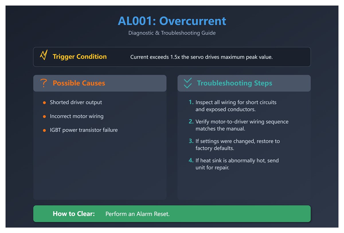
1. AL001 Overcurrent
(1) Trigger conditions and causes of abnormal alarms
Condition: The main circuit current value exceeds 1.5 times the servo drive's instantaneous maximum current peak value.
Cause:
- Driver output shorted.
- Abnormal motor wiring.
- IGBT abnormality.
(2) Inspection and disposal
- Check the motor and driver wiring status or conductor body for short circuits, and prevent metal conductors from being exposed. Check the wiring sequence of the motor to the driver according to the wiring instructions in the manual.
- If abnormal heat sink temperature is found, please send it back to dealer or original factory for repair. Check if the setting value is much larger than the factory default value, it is recommended to revert to the original factory default value first, and then correct it quantity by quantity.
(3) Methods of elimination
Alien Alarm Reset.
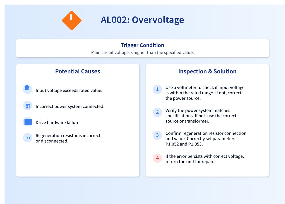
2. AL002 Overvoltage
(1) Trigger conditions and causes of abnormal alarms
Condition: The main circuit voltage value is higher than the specification voltage value.
Cause:
- The main circuit input voltage is higher than the rated allowable voltage value.
- Power input error (not the correct power system).
- Drive hardware failure.
- The regeneration resistor is selected incorrectly or the external regeneration resistor is not connected.
(2) Inspection and disposal
- Use a voltmeter to determine if the main circuit input voltage is within the rated allowable voltage (refer to Appendix A specifications), if it exceeds the set value, use the correct voltage source or series regulator; use a voltmeter to determine if the power supply system is in accordance with the specification definition, if it is not, use the correct voltage source or series transformer.
- When this error occurs even though the main circuit input voltage is within the rated allowable voltage value as determined by a voltmeter, return it to the dealer or factory for repair.
- Confirm the connection status of the regeneration resistor and recalculate the regeneration resistor value, and reset the parameter values of P1.052 and P1.053 correctly.
(3) Methods of elimination
Alien Alarm Reset.
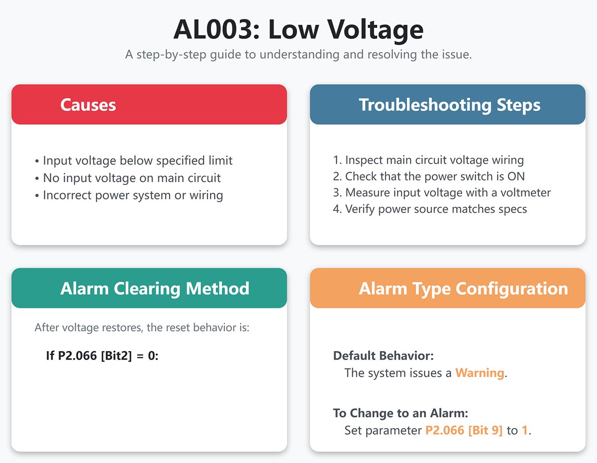
3. AL003 Low Voltage
(1) Trigger conditions and causes of abnormal alarms
Condition:
- The main circuit voltage is lower than the specification voltage. The type of abnormality for this alarm is preset as Warning, if you want to set it as Alarm, you can set P2.066 [Bit 9] to 1.
- DC Bus voltage value is less than P4.024 x √2.
Cause:
- The main circuit input voltage is lower than the rated allowable voltage value.
- No input voltage on the main circuit.
- Power input error (not the correct power system).
(2) Inspection and disposal
- Reconfirm the voltage wiring and check that the main circuit input voltage wiring is normal.
- Reconfirm the power switch and measure the main circuit voltage with a voltmeter.
- Determine with a voltmeter whether the power supply system is as defined in the specifications and check that the correct voltage source or series transformer is used.
(3) Methods of elimination
Follow the setting of P2.066 [Bit2] to exclude AL003:
- P2.066 [Bit2] is set to 0. After the voltage is restored, the abnormal alarm needs to be cleared by DI.ARST.
- P2.066 [Bit2] is set to 1. After the voltage is restored, the abnormal alarm is cleared automatically.
4. AL004 Motor Matching Abnormal
(1) Trigger conditions and causes of abnormal alarms
Condition: The motor corresponding to the driver is incorrect.
Cause:
- The motor is incorrectly matched.
- The motor encoder is loose.
- The motor encoder is damaged.
(2) Inspection and disposal
- Replace the motor with one that matches.
- Check and reinstall the motor encoder connector.
- If it is found that the motor encoder is abnormal, replace the motor.
(3) Methods of elimination
Re-energize to clear.
5. AL005 Rebirth Error
(1) Trigger conditions and causes of abnormal alarms
Condition: an error occurs during rebirth.
Cause:
- The regeneration resistor is selected incorrectly or the external regeneration resistor is not connected.
- No regenerative resistor is used, but the user has not set the regenerative resistor capacity parameter (P1.053) to zero.
- Parameter setting error (P1.052, P1.053).
(2) Inspection and disposal
- Confirm the connection status of the regeneration resistor and recalculate the value of regeneration resistor, reset the parameter values of P1.052 and P1.053 correctly, and if the alarm is still not lifted, please send the drive back to the factory.
- If no regenerative resistor is used, set the regenerative resistor capacity (P1.053) to zero.
- Reset and confirm the set values of regenerative resistor value (P1.052) and regenerative resistor capacity (P1.053) correctly.
(3) Methods of elimination
Alien Alarm Reset.
6. AL006 Overload
(1) Trigger conditions and causes of abnormal alarms
Condition: Motor and drive overload.
Cause:
- Exceeding the rated load of the drive and continuous use.
- Improperly set control system parameters.
- The motor and position detector are wired incorrectly.
- The position detector of the motor is defective.
(2) Inspection and disposal
- The average load ratio [%] can be monitored to see if the average load ratio [%] consistently exceeds 100% or more after setting the drive status display (P0.002) to 12. If it consistently exceeds 100% or more (refer to Appendix A Load Ratio vs. Run Time graph), the motor capacity needs to be increased or the load reduced.
- Check the mechanical system for oscillating vibration or acceleration and deceleration settings that are too fast.
- Check that U, V, W and motor encoder wiring is correct.
- Return the motor to the dealer or factory for service.
(3) Methods of elimination
Alien Alarm Reset.
7. AL007 Excessive Speed Control Error
(1) Trigger conditions and causes of abnormal alarms
Condition: The error between the speed command and speed return is greater than the allowable setting (P2.034).
Cause:
- The speed input command changes too drastically.
- The speed control error warning condition (P2.034) is not set properly.
- Incorrect wiring of U, V, W and motor encoder.
(2) Inspection and disposal
- Use a signal detector to check whether the input analog voltage signal is abnormal, you can adjust the input signal variation rate or turn on the filtering function.
- Check that the parameter value of the speed control error warning condition (P2.034) is set appropriately.
- Check for proper wiring of U, V, W and motor encoder.
(3) Methods of elimination
Alien Alarm Reset.
8. AL008 Abnormal Pulse Control Command
(1) Trigger conditions and causes of abnormal alarms
Condition: The input frequency of the pulse command exceeds the hardware interface tolerance.
Cause: Pulse command frequency is higher than the rated input frequency.
(2) Inspection and disposal
Check that the input frequency does not exceed the rated input frequency with a pulse frequency check meter and enter the pulse frequency correctly.
(3) Methods of elimination
Alien Alarm Reset.
9. AL009 Excessive Position Control Error
(1) Trigger conditions and causes of abnormal alarms
Condition: The error between the position command and position return is greater than the allowable setting value (P2.035).
Cause:
- The maximum position error parameter is set too small.
- The gain value is set too small.
- Torque limit or speed limit is too low.
- Excessive external load.
- The electronic gear ratio ratio is not set properly.
- The power cord is loose.
- The maximum speed limit is too low.
(2) Inspection and disposal
- Check the maximum position error setting value for the excessive position control error warning condition (P2.035), and increase the setting value if necessary.
- Check whether the gain value is appropriate according to the actual usage conditions.
- If the speed and torque limiting function is not needed, please turn off parameter P1.002; otherwise, please check whether the internal speed limiting (P1.009 ~ P1.011) and internal torque limiting (P1.012 ~ P1.014) setting values are correct.
- Check the external load and if necessary reduce the external load or re-evaluate the motor capacity.
- Check whether the ratio of P1.044 and P1.045 is appropriate according to the actual usage conditions and set the correct value.
- Check for loose power cords.
- Check that the maximum speed limit (P1.055) setting is not too low.
(3) Methods of elimination
Alien Alarm Reset.
10. AL010 Abnormal Voltage in Regenerative State
(1) Trigger conditions and causes of abnormal alarms
Condition: an error occurs during rebirth.
Cause:
- In the regeneration state, the regeneration voltage is maintained at 400V for a period of time. The cause may be that the regeneration resistor is wrongly selected or the external regeneration resistor is not connected.
- No regenerative resistor is used, but the user has not set the regenerative resistor capacity (P1.053) to zero.
(2) Inspection and disposal
- Confirm the connection status of the regeneration resistor and recalculate the value of regeneration resistor, reset the parameter values of P1.052 and P1.053 correctly, and if the alarm is still not lifted, please send the drive back to the factory.
- If no regenerative resistor is used, set the regenerative resistor capacity (P1.053) to zero.
(3) Methods of elimination
Alien Alarm Reset.
11. AL011 Position Detector Abnormal
(1) Trigger conditions and causes of abnormal alarms
Condition: The position detector generates an abnormal pulse signal.
Cause:
- Position detector wired incorrectly.
- Loose position detector connector.
- Bad position detector wiring.
- Encoder communication is disconnected due to interference.
- The position detector is damaged.
(2) Inspection and disposal
- Verify that the wiring is in accordance with the recommended wiring in the instruction manual and that the wiring is correct.
- Look for a loose CN2 and position detector connector on the drive. If loose, reinstall.
- Check whether there is any defective wiring or broken wires between the detector and the CN2 of the drive and the motor, and replace the connectors and wires if there are.
- Please monitor the encoder communication error rate P0.002 = -80, if this value will continue to accumulate, it means that there is interference, please check the following items: (a) Confirm whether the motor grounding terminal is indeed grounded, please connect the grounding terminal of the power cord (green) with the heat sink of the drive. (b) Make sure the encoder signal line is normal, and separate the encoder signal line from the power supply or high current line to avoid interference. (c) Use encoder cables with isolation mesh and pull out the isolation mesh wire to ground it properly.
- If all of the above checks have been completed and the alarm still cannot be eliminated, replace the motor.
(3) Methods of elimination
Re-energize to clear.
12. AL012 Calibration Anomaly
(1) Trigger conditions and causes of abnormal alarms
Condition: When performing electrical calibration, the calibration value exceeds the allowable value.
Cause:
- Analog input contacts are not properly zeroed.
- Detection of component damage.
(2) Inspection and disposal
- Measure whether the voltage of the analog input contact is the same as the ground potential.
- Power reset test; if reset is still abnormal, return drive to dealer or factory for service.
(3) Methods of elimination
Clear after removing CN1 wiring and performing auto-correct.
13. AL013 Emergency Stop
(1) Trigger conditions and causes of abnormal alarms
The emergency stop switch is pressed.
(2) Inspection and disposal
Verify that the emergency switch is off.
(3) Methods of elimination
EMGS Disarm automatically clears this alarm.
14. AL014 Reverse Limit Exception
(1) Trigger conditions and causes of abnormal alarms
Condition: The reverse limit switch is triggered.
Cause:
- The reverse limit switch is triggered.
- The servo system is not stable enough.
(2) Inspection and disposal
- Verify that the reverse limit switch is closed.
- Confirm the parameter settings or re-evaluate the motor capacity.
(3) Methods of elimination
Automatically clears when out of limits.
15. AL015 Positive Limit Anomaly
(1) Trigger conditions and causes of abnormal alarms
Condition: Positive limit switch is triggered.
Cause:
- The positive limit switch is triggered.
- The servo system is not stable enough.
(2) Inspection and disposal
- Verify that the positive limit switch is closed.
- Confirm the parameter settings or re-evaluate the motor capacity.
(3) Methods of elimination
Automatically clears when out of limits.
16. AL016 IGBT Temperature Abnormality
(1) Trigger conditions and causes of abnormal alarms
Condition: Abnormal IGBT temperature.
Cause:
- Exceeds the drive's rated load and is used continuously.
- Driver output shorted.
- The site ambient temperature is too low.
(2) Inspection and disposal
- Check if the load is too high or the motor current is too high, try to increase the motor capacity or reduce the load.
- Check that the drive outputs are wired correctly.
- The field temperature is below 0°C. The permissible ambient temperature is 0°C to 55°C.
(3) Methods of elimination
Alien Alarm Reset.
17. AL017 Memory Exception
(1) Trigger conditions and causes of abnormal alarms
Condition: Memory (EEPROM) access exception.
Cause:
- Parameter data is written abnormally or the parameter setting is out of the tolerance range.
- When power is supplied, the data in ROM is destroyed or there is no data in ROM.
(2) Inspection and disposal
Press the panel SHIFT key to display EXGAB.
X = 1, 2, 3
G = group code of the parameter
AB = number of the parameter hexadecimal code
If the panel displays E320A, it means the parameter is P2.010; if it displays E3610, it means the parameter is P6.016, please check the pen parameter.
- Press the SHIFT key on the panel to display the parameter code; if this alarm occurs during power up, it means that the value of a parameter is out of the setting range, and power up can be resumed after correcting it. If this alarm occurs during normal operation, it means that there is an error in writing the parameter, which can be cleared by DI.ARST.
- Press the SHIFT key on the panel to display E100X or E0001; if this alarm occurs when power is supplied, it is usually because the data in ROM is corrupted or there is no data in ROM, please send it back to the dealer or the original factory for repair.
(3) Methods of elimination
If it occurs on power-up, please reset the parameters before re-powering; if it occurs during operation, please carry out alien alarm reset.
18. AL018 Position Detector Output Abnormal
(1) Trigger conditions and causes of abnormal alarms
Condition: The detector output pulse frequency is higher than the hardware maximum output frequency.
Cause:
- Detector pulse resolution is set too high.
- The encoder cable suffers from stray wave interference or the cable is damaged, resulting in abnormal communication.
- The encoder is abnormal.
(2) Inspection and disposal
- Please set the parameters correctly, P1.076 and P1.046 must meet the conditions: browse here.
- Monitor the encoder communication error rate P0.002 = -80, if this value continues to accumulate, it indicates interference, please check the following items:
- To verify that the motor ground terminal is actually grounded, connect the ground terminal (yellow-green) of the power cord to the drive's heat sink.
- Make sure the encoder signal line is normal, and separate the encoder signal line from the power supply or high current line to avoid interference.
- Use encoder cables that contain an isolation mesh and pull out the isolation mesh wire for proper grounding.
- Check whether an encoder alarm (AL011, AL024, AL025, AL026) is generated along with the abnormal status log (P4.000 to P4.004). If an alarm occurs, check and troubleshoot the alarm.
- If OA/OB pulses are not required, set P2.065 [Bit 13] to 1 to turn off position detector output exception (AL018) detection.
(3) Methods of elimination
- Alien Alarm Reset.
- Please contact your dealer.
19. AL020 Serial Communication Timeout
(1) Trigger conditions and causes of abnormal alarms
Condition: RS-485 communication is abnormal.
Cause:
- The parameter of Modbus communication timeout setting (P3.004) is not set properly.
- The drive has not received a communication command for an extended period of time (refer to P3.004).
(2) Inspection and disposal
- Check the settings of the parameters related to communication overdue and set their parameter values correctly.
- Check for loose or broken communication wires and make sure they are wired correctly.
(3) Methods of elimination
Alien Alarm Reset.
20. AL022 Abnormal Main Circuit Power Supply
(1) Trigger conditions and causes of abnormal alarms
Condition: The main circuit power supply RST power cord may be loose or not energized. The exception type of this alarm is preset as Warning, if you want to set it as Alarm, you can set P2.066 [Bit 12] to 1.
Cause: Abnormal main circuit power supply.
(2) Inspection and disposal
Check if the RST power cord is loose or without power supply. 1.5 kW (including) drive needs no power supply in all three phases to generate this alarm; 2 kW (including) drive will generate this alarm as long as there is no power supply in one phase. Please make sure to connect the power supply, if the power supply is normal but still can not rule out the alarm, please send the drive back to the dealer or the original factory for repair.
(3) Methods of elimination
Alien Alarm Reset.
21. AL023 Advance Overload Warning
(1) Trigger conditions and causes of abnormal alarms
Pre-overload warning.
(2) Inspection and disposal
- To determine if overloaded use has occurred, refer to AL006 Alarm Disposition.
- Check whether the parameter setting of motor overload output warning (P1.056) is too small. If the setting is too small, increase the setting value of parameter P1.056 or make the setting value greater than 100 to cancel the warning function.
(3) Methods of elimination
Alien Alarm Reset.
22. AL024 Encoder Initial Magnetic Field Error
(1) Trigger conditions and causes of abnormal alarms
Condition: Encoder magnetic field position U, V, W is incorrect.
Cause: Incorrect initial magnetic field of the encoder (incorrect magnetic field position U, V, W).
(2) Inspection and disposal
- To verify that the motor ground terminal is actually grounded, connect the ground terminal (green) of the power cord to the drive's heat sink.
- Make sure the encoder signal line is normal, and separate the encoder signal line from the power supply or high current line to avoid interference.
- Please use the encoder cable with isolation mesh and pull out the isolation mesh wire for proper grounding. If there is no improvement, please send the motor back to the dealer or factory for repair.
(3) Methods of elimination
Re-energize to clear.
23. AL025 Encoder Internal Error
(1) Trigger conditions and causes of abnormal alarms
Condition: Encoder internal memory abnormality and internal counter abnormality.
Cause:
- Encoder internal error (internal memory exception and internal counter exception).
- On power-up, the motor rotates due to mechanism inertia or other factors.
(2) Inspection and disposal
- To verify that the motor ground terminal is actually grounded, connect the ground terminal (green) of the power cord to the drive's heat sink.
- Make sure the encoder signal line is normal, and separate the encoder signal line from the power supply or high current line to avoid interference.
- Use encoder cables that contain an isolation mesh and pull out the isolation mesh wire for proper grounding.
- Ensure that the motor shaft center remains stationary at the moment of power-up.
(3) Methods of elimination
Re-energize to clear.
24. AL026 Encoder Internal Data Reliability Error
(1) Trigger conditions and causes of abnormal alarms
Condition: three consecutive abnormalities in internal data.
Cause:
- External disturbances result.
- Encoder hardware failure.
(2) Inspection and disposal
Please check the following items for interference:
- To verify that the motor ground terminal is actually grounded, connect the ground terminal (green) of the power cord to the drive's heat sink.
- Make sure the encoder signal line is normal, and separate the encoder signal line from the power supply or high current line to avoid interference.
- Check whether the wire of the position detector is using isolation net.
- The communication error rate of the encoder line can be monitored by setting P0.002 = -80 from the panel. If the value is greater than 0 and continues to increase, double-check points 1 to 3 of the disposition. If the value is 0, send the motor back to the dealer or factory for repair.
(3) Methods of elimination
Re-energize to clear.
25. AL027 Encoder Internal Reset Error
(1) Trigger conditions and causes of abnormal alarms
Condition: The encoder chip is reset abnormally.
Cause: Encoder chip reset.
(2) Inspection and disposal
- Check and verify that the encoder signal wires do not have a poor contact condition.
- Check that the power supply to the encoder is stable and that it does use cables containing isolation grids.
- Check that the operating temperature of the encoder is not higher than 95°C. Eliminate the cause of the increase in temperature and allow it to cool down before operating. If there is no improvement in any of the above cases, please return the motor to the dealer or factory for repair.
(3) Methods of elimination
Re-energize to clear.
26. AL028 Abnormal Battery Voltage or Internal Encoder Error
(1) Trigger conditions and causes of abnormal alarms
Condition: Battery voltage higher than specification (> 3.8V) or encoder signal error.
Cause:
- Battery voltage is too high.
- Internal encoder error.
(2) Inspection and disposal
- Check the drive for charging circuitry, if pin 1 (5V) of CN2 is incorrectly connected to BAT+, this will cause the drive's 5V supply to charge the battery.
- Check for abnormal battery installation (high voltage > 3.8V) or use of non-Delta battery packs.
- To verify that the motor ground terminal is actually grounded, connect the ground terminal (green) of the power cord to the drive's heat sink.
- Make sure the encoder signal line is normal, and separate the encoder signal line from the power supply or high current line to avoid interference.
- Check whether the wire of position detector is using isolation net. If there is no improvement, please send the drive and motor back to the distributor or factory for repair.
(3) Methods of elimination
Re-energize to clear.
27. AL029 Gray Code Error
(1) Trigger conditions and causes of abnormal alarms
One lap absolute position error.
(2) Inspection and disposal
Re-energize and run the motor to verify that the alarm returns. If the alarm still occurs, the encoder must be replaced.
(3) Methods of elimination
Re-energize to clear.
28. AL02A Encoder Revolution Count Error
(1) Trigger conditions and causes of abnormal alarms
Condition: An abnormality occurred in the encoder revolution count.
Cause: Abnormalities in the internal signals of the encoder have occurred, resulting in an incorrect number of turns.
(2) Inspection and disposal
Please return the motor to the dealer or factory for service.
(3) Methods of elimination
None.
29. AL02B Motor Data Exception
(1) Trigger conditions and causes of abnormal alarms
Motor internal data access error.
(2) Inspection and disposal
Please return the motor to the factory for inspection.
(3) Methods of elimination
None.
30. AL02F Anti-blocking Protection
(1) Trigger conditions and causes of abnormal alarms
Condition: Motor speed is maintained at 10 rpm or less or blocked and the drive is overloaded.
Cause:
- Motor or connecting mechanism malfunction deadlocked resulting in failure to rotate.
- Extremely low RPM or excessive blocking time.
(2) Inspection and disposal
- Increase motor speed to reduce blocking time.
- Check the motor connection mechanism for proper operation.
- Check that U, V, W and motor encoder wiring is correct.
- Return the motor to the dealer or factory for service.
(3) Methods of elimination
Alien Alarm Reset.
31. AL030 Motor Collision Error
(1) Trigger conditions and causes of abnormal alarms
Condition: When the motor strikes a hard device, the torque setting of P1.057 is reached and the set time of P1.058 elapses.
Cause:
- Verify that the motor crash protection function (P1.057) is activated, and set the parameter value to 0 if it is turned on by mistake.
- Check if the setting value of P1.057 is too low and the time setting of P1.058 is too short. Please set the value of P1.057 according to the actual torque, too low a value may cause false operation, too high a value will lose the protection function.
(2) Inspection and disposal
Re-energize and run the motor to verify that the alarm returns. If the alarm still occurs, the encoder must be replaced.
(3) Methods of elimination
Alien Alarm Reset.
32. AL031 Motor Power Cable error/Break Detection
(1) Trigger conditions and causes of abnormal alarms
Condition: Motor power (U, V, W) and ground (GND) wires are incorrectly wired or disconnected.
Cause: Incorrectly wired or disconnected motor power (U, V, W) and ground (GND) wires. The protection against disconnection is enabled or disabled by parameter P2.065 [Bit 9], the preset is disabled. Miswire detection is enabled or disabled by parameter P2.065 [Bit 8] and is preset to be disabled.
(2) Inspection and disposal
Check if the motor power (U, V, W) and ground (GND) wires are disconnected, please follow the manual for proper wiring and grounding.
(3) Methods of elimination
Re-energize to clear.
33. AL032 Abnormal Encoder Vibration
(1) Trigger conditions and causes of abnormal alarms
Condition: Abnormal vibration occurs inside the encoder.
Cause: Abnormalities in the internal signal or mechanism of the encoder, and the encoder returns an incorrect signal.
(2) Inspection and disposal
Check that the vibration range of the motor is within 2.5 G. If you confirm that the vibration specification is within the specification, return the motor to your dealer or the original manufacturer for repair.
(3) Methods of elimination
Alarm reset or re-power-up clears.
34. AL033 Motor Abnormality
(1) Trigger conditions and causes of abnormal alarms
The motor is abnormal.
(2) Inspection and disposal
None.
(3) Methods of elimination
Please return the motor to the factory for service.
35. AL034 Encoder Internal Communication Exception
(1) Trigger conditions and causes of abnormal alarms
Condition:
- Absolute encoder chip internal communication abnormality.
- Other types of encoder internal exceptions.
Cause: Abnormal communication within the encoder.
(2) Inspection and disposal
- Check to see if the battery wiring is reversed or loose. If loose, reconnect battery wiring and repower.
- Check that the battery voltage is normal.
- Absolute type position detector chip internal communication abnormality, please replace the motor.
(3) Methods of elimination
Re-energize to clear.
36. AL035 Encoder Temperature Exceeds Protection Limit
(1) Trigger conditions and causes of abnormal alarms
Condition: The encoder temperature exceeds the upper limit value by 100°C.
Reason: The temperature of the encoder exceeds 100°C.
(2) Inspection and disposal
Set P0.002 to -124 to read the temperature and see if the displayed temperature is below 100°C. If the temperature exceeds the upper limit, reduce the temperature by dissipating heat. If the temperature difference from the actual motor temperature is more than 30°C, send the motor back to the factory for repair.
(3) Methods of elimination
Allow the motor temperature sensor to display below 100°C before reapplying power to clear.
37. AL036 Encoder Alarm Status Error
(1) Trigger conditions and causes of abnormal alarms
Condition: A status exception occurs within the encoder.
Cause: The encoder sends out a false alarm signal, but the drive reads back the encoder false alarm status without error.
(2) Inspection and disposal
- To verify that the motor ground terminal is actually grounded, connect the ground terminal (green) of the power cord to the drive's heat sink.
- Make sure the encoder signal line is normal, and separate the encoder signal line from the power supply or high current line to avoid interference.
- Use encoder cables that contain an isolation mesh and pull out the isolation mesh wire for proper grounding.
- Check the motor speed, please make sure the motor speed is within the rated range. If there is no improvement, please return the motor to the dealer or factory for repair.
(3) Methods of elimination
Alarm reset or re-power-up clears.
38. AL042 Analog Speed Voltage Input Too High
(1) Trigger conditions and causes of abnormal alarms
The analog speed voltage exceeds the set parameter P1.083.
(2) Inspection and disposal
Check and verify that there is no problem with the analog speed voltage source. Check the setting of parameter P1.083 and set it to 0 if this function is not used.
(3) Methods of elimination
Alien Alarm Reset.
39. AL044 Drive Function Utilization Warning
(1) Trigger conditions and causes of abnormal alarms
Condition: Turn on the motor control function of the MultiDrive.
Cause: Drive function utilization alarm.
(2) Inspection and disposal
- Check the filters that are currently turned on and evaluate the need to turn them on.
- Setting P2.066 [Bit 4] to 1 turns off the display of this alarm.
(3) Methods of elimination
- Turn off the filters that do not need to be used, such as low-pass smoothing filter (P1.006 ~ P1.008), Moving filter (P1.068), low-frequency vibration suppression (P1.025 ~ P1.028), Flexure Compensation (P1.089 ~ P1.094), Notch Filter (Group 1 to 5), Friction Compensation (P1.062), and Motor Crash Protection - Torque Percentage (P1.057). P1.062) and Motor Crash Protection - Torque Percentage (P1.057).
- Set P2.066 [Bit 4] to 1 and re-power up.
40. AL045 Electronic Gear Ratio Setting Error
(1) Trigger conditions and causes of abnormal alarms
Condition: When the electronic gear ratio setting is out of range (1 ~ 262144), this alarm occurs when power is restored.
Cause: The electronic gear ratio was found to be set incorrectly after the servo was powered up.
(2) Inspection and disposal
Check that the electronic gear ratio setting is within the normal range (1 ~ 262144). If the setting is incorrect, correct the electronic gear ratio and re-power up the unit.
(3) Methods of elimination
Once set correctly, re-power up to clear.
41. AL048 Position Detector Output Abnormality
(1) Trigger conditions and causes of abnormal alarms
Condition: The detector output pulse frequency is higher than the hardware maximum output frequency.
Cause:
- Detector pulse resolution is set too high.
- The encoder cable suffers from stray wave interference or the cable is damaged, resulting in abnormal communication.
- The encoder is abnormal.
(2) Inspection and disposal
- Please set the parameters correctly, P1.076 and P1.046 must meet the conditions: browse here.
- Monitor the encoder communication error rate P0.002 = -80, if this value continues to accumulate, it indicates interference, please check the following items:
- To verify that the motor ground terminal is actually grounded, connect the ground terminal (green) of the power cord to the drive's heat sink.
- Make sure the encoder signal line is normal, and separate the encoder signal line from the power supply or high current line to avoid interference.
- Use encoder cables that contain an isolation mesh and pull out the isolation mesh wire for proper grounding.
- Check whether an encoder alarm (AL011, AL024, AL025, AL026) accompanies the abnormal status green (P4.000 to P4.004). If an alarm occurs, check and troubleshoot the alarm.
- If OA/OB pulses are not required, set P2.065 [Bit13] to 1 to turn off detector output abnormality detection.
(3) Methods of elimination
- Alien Alarm Reset.
- Please contact your dealer.
42. AL053 Motor Parameters Not Recognized
(1) Trigger conditions and causes of abnormal alarms
Condition: If the Motor Parameter Recognition Wizard function has not been executed or the recognition failed, the alarm will be displayed once the Servo Servo is turned on.
Cause: The motor has not executed the Motor Parameter Recognition Wizard function or the execution has failed.
(2) Inspection and disposal
Please execute or re-execute the Motor Parameter Recognition Wizard function.
(3) Methods of elimination
The alarm is canceled by switching the servo to Servo Off state.
43. AL056 Motor Speed Too High
(1) Trigger conditions and causes of abnormal alarms
Condition: When the motor speed (after filtering) exceeds the setting of P1.111, the servo drive immediately switches to the Servo Off state and displays this alarm.
Cause: This alarm alerts the user that the motor speed has reached the upper limit of the current setting (P1.111).
(2) Inspection and disposal
- Check the cause of high motor speed, such as P1.111 setting too small or bandwidth not properly set.
- The user can evaluate the motor speed and the condition of the mechanism. If both are allowed, the speed can be increased by itself and the setting of P1.111 can be increased.
(3) Methods of elimination
Alien Alarm Reset.
44. AL05C Abnormal Motor Position Feedback
(1) Trigger conditions and causes of abnormal alarms
Condition: Sudden jump abnormality in motor position return.
Cause:
- The encoder return is not normal or the encoder is damaged.
- The encoder teachback is disturbed.
(2) Inspection and disposal
- Check whether the feedback signal is abnormal. Using a software oscilloscope, select [Feedback Position PUU] for channel type and sample at 16 kHz or 20 kHz, manually push the motor and monitor the feedback value for abnormal discontinuous jumps.
- Check if there is any interference in the return signal that causes the motor position return to generate a sudden jump abnormality.
- Check if the communication error rate increases due to interference. For example, to check the communication error rate: P0.017 = -80, read and observe if the value of P0.009 is not 0 and tends to increase.
(3) Methods of elimination
Re-energize to clear.
45. AL060 Absolute Position Lost
(1) Trigger conditions and causes of abnormal alarms
Condition: Absolute encoders lose the number of revolutions recorded internally due to low battery voltage or interruption of power supply.
Cause:
- Battery voltage is too low.
- Replace the battery with the drive control power off.
- Batteries are not installed after activating the absolute type function.
- Poor contact or disconnection of the battery supply line.
(2) Inspection and disposal
- Check if the battery voltage is lower than 2.9V; after replacing the battery, re-establish the absolute type origin coordinates.
- Do not replace or remove the battery with the drive control power off.
- The following inspections are recommended:
- Install the battery.
- Check the battery power wiring from the external battery box to the drive.
- Check the encoder wiring.
- Verify that the wiring allows battery power to be supplied to the encoder properly, and re-establish absolute home coordinates.
(3) Methods of elimination
After connecting or repairing the wiring so that battery power can be supplied to the encoder properly, re-establish the absolute home position coordinates.
46. AL061 Encoder Voltage Too Low
(1) Trigger conditions and causes of abnormal alarms
Condition: The battery voltage of the absolute encoder is below the norm (3.1V).
Cause: Low battery voltage.
(2) Inspection and disposal
- Use the monitor variable 26h to read if the battery voltage is below 3.1V.
- Measure the battery voltage to see if it is below 3.1 V. If it is too low, replace the battery with the drive control power on.
(3) Methods of elimination
Automatically cleared.
47. AL062 Absolute Position Circle Overrun (Encoder)
(1) Trigger conditions and causes of abnormal alarms
Condition: Absolute type position circle out of maximum range: -32768 ~ +32767.
Cause: Stroke out of range.
(2) Inspection and disposal
Check that the number of motor revolutions is within the range of -32768 to +32767 revolutions. If out of range, re-establish absolute home position coordinates.
(3) Methods of elimination
Re-energize to clear.
48. AL064 Encoder Vibration Warning
(1) Trigger conditions and causes of abnormal alarms
Condition: Abnormal vibration occurs inside the encoder.
Cause: An abnormality occurs in the internal signal or mechanism of the encoder, and the encoder returns a warning signal.
(2) Inspection and disposal
Verify that the motor vibration range is within 2 G. If you confirm that the vibration specification is within the specification, return the motor to the dealer or the original manufacturer for repair.
(3) Methods of elimination
Alarm reset or re-power-up clears.
49. AL066 Absolute Position Circle Overrun (Driver)
(1) Trigger conditions and causes of abnormal alarms
Condition: The number of absolute type position turns exceeds half of the turn resolution.
- Delta motors have a turn count of -32768 to +32767.
- For third-party motors, please make your own calculations according to the motor specifications.
Cause: Stroke out of range.
(2) Inspection and disposal
- Check that the number of motor revolutions is within the range. If out of range, re-establish absolute type origin coordinates.
- Check that the indexing coordinates do not overflow function is off. If it is off, the indexing non-overflow function needs to be turned on (P2.069.Z = 1).
(3) Methods of elimination
Clear after re-establishing the absolute type origin coordinates.
50. AL067 Encoder Temperature Warning
(1) Trigger conditions and causes of abnormal alarms
Condition: The encoder temperature exceeds the warning value (85°C) but is within the upper temperature protection limit (100°C).
Reason: High encoder temperature warning (85°C ~ 100°C).
(2) Inspection and disposal
Set P0.002 to -124 to read the encoder temperature and see if it matches the motor temperature. If the temperature is too high, increase the heat dissipation or reduce the temperature during operation. If the actual temperature difference between the encoder and motor is more than 30°C, return the motor to the factory for service.
(3) Methods of elimination
Re-energize to clear.
51. AL068 Absolute Data I/O Transfer Error
(1) Trigger conditions and causes of abnormal alarms
Condition: Timing error in reading absolute position using DIO.
Cause:
- Timing error.
- The reading is out of time.
(2) Inspection and disposal
- Correct I/O read timing:
- DI.ABSQ must wait for DO.ABSR Off before cutting Off.
- DI.ABSQ must wait for DO.ABSR On before cutting On.
- Check whether the interval between DO.ABSR turning On and DI.ABSQ turning On exceeds 200 ms. The correct operation is to read DO.ABSD within 200 ms after DO.ABSR turns On and the absolute position bit data is ready, switch DI.ABSQ to On, and notify the driver of the completion of data bit reading.
(3) Methods of elimination
Re-energize to clear.
52. AL069 Motor Type Error
(1) Trigger conditions and causes of abnormal alarms
It is not permitted to activate the absolute type function for incremental motors, since incremental motors do not have an absolute type function.
(2) Inspection and disposal
- Check whether the motor is an incremental or absolute encoder.
- Check the setting of parameter P2.069 and set the value correctly. If the absolute function is not used, set parameter P2.069.X to zero.
(3) Methods of elimination
Set parameter P2.069.X to 0 and re-power up.
53. AL06A Absolute Position Lost
(1) Trigger conditions and causes of abnormal alarms
Absolute position loss can be categorized into two situations. One is when the absolute coordinates have not been established, so the home position is lost after the absolute home position coordinates have been established and the power is turned on again; the other is when an abnormality occurs, and the AL06A abnormal alarm occurs after the absolute home position coordinates have been established and the power is turned on again.
No coordinates established
Condition:
- The drive is being used for the first time since it was shipped from the factory.
- When the battery is dead and the drive control power supply is disconnected.
- When a bus communication type servo is used with an absolute type motor, the first time the electronic gear ratio is used or modified, the user gives an absolute type position command.
Cause:
- The drive is being used for the first time since it was shipped from the factory, so absolute type origin coordinates have not yet been established.
- The absolute position is maintained by electric power, so when the battery is dead and the driver is powered off, the absolute position of the servo is lost.
- After modifying the electronic gear ratios, the coordinate system of the communication type needs to be re-established.
Abnormalities
Condition:
- Damage to the encoder wires (both external and internal).
- Battery power supply has experienced a momentary power failure (i.e., insufficient battery capacity).
- Absolute type motor abnormality.
- When using the battery box, J1 and J2 are wired in reverse.
- When the battery voltage is below 2.9V.
Cause:
- The supply power is unstable due to damage to the encoder wire.
- The cause of instantaneous power failure may come from a loose connector on the battery compartment itself, or excessive vibration of the machine.
- An abnormality has occurred in the absolute encoder of this motor.
- If J1 and J2 are wired backwards, the battery will not charge the capacitor. The purpose of the capacitor is to act as a buffer mechanism when switching the battery power supply at the moment of driver power failure.
(2) Inspection and disposal
- Verify that absolute type origin coordinates have been established.
- Avoid changing the battery when the drive is powered off. It is recommended to do the replacement with the drive powered up so that the absolute encoder retains a continuous power supply.
- Replace the motor.
- Make sure that the J1 terminal in the battery compartment is connected to the battery and the J2 terminal is connected to the drive.
- Replace the encoder wire. The internal part of the wire is not easy to identify and needs to be X-rayed.
- Check the wire for loose condition, if there is no loose condition, replace the battery box for cross test.
- Re-establish the absolute type origin coordinates.
(3) Methods of elimination
Absolute type origin coordinates will be cleared automatically when the establishment is completed.
54. AL06B Drive Internal Coordinates and Encoder Coordinates Error Is Too Large
(1) Trigger conditions and causes of abnormal alarms
Condition: When the absolute type motor is powered by a battery, the number of revolutions is greater than half of the revolution resolution.
Cause: The difference between the internal drive coordinates and the encoder coordinates is too large.
(2) Inspection and disposal
The mechanism was not secured properly when the machine was transported, causing the motor to rotate.
(3) Methods of elimination
Re-establish the absolute type origin coordinates.
55. AL06E Encoder Type Not Recognized
(1) Trigger conditions and causes of abnormal alarms
The drive does not recognize the encoder type.
(2) Inspection and disposal
None.
(3) Methods of elimination
Replace the motor immediately.
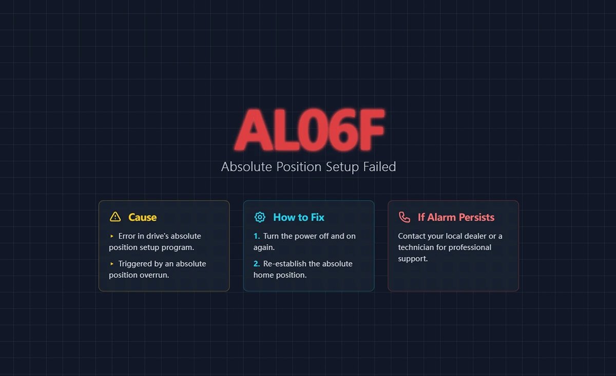
56. AL06F Absolute Position Establishment Not Completed
(1) Trigger conditions and causes of abnormal alarms
Condition: Absolute position overrun is established.
Cause: Abnormality in the drive's absolute position establishment program.
(2) Inspection and disposal
If this alarm occurs again after re-powering and re-establishing the home position, please contact your local dealer or technician.
(3) Methods of elimination
Re-power up and re-establish absolute type origin coordinates.
57. AL070 Encoder Read/Write Incomplete Warning
(1) Trigger conditions and causes of abnormal alarms
The encoder read/write program is not completed.
(2) Inspection and disposal
Verify that the wiring is correct or that the connectors are not loose, and wire correctly. If the error persists, contact the original manufacturer.
(3) Methods of elimination
Re-energize to clear.
58. AL071 Encoder Turn Error
(1) Trigger conditions and causes of abnormal alarms
Condition: The encoder internal revolution count is abnormal.
Cause: Encoder lap counting error due to abnormal internal encoder signal.
(2) Inspection and disposal
If there is no improvement after resetting the abnormal alarm, return the motor to the dealer or factory for service.
(3) Methods of elimination
Alien Alarm Reset.
59. AL072 Encoder Overspeed
(1) Trigger conditions and causes of abnormal alarms
- Under drive power: speeds over 8,800 rpm.
- On battery power: over 10,000 rpm.
- Battery voltage is too low.
(2) Inspection and disposal
- To verify that the motor ground terminal is actually grounded, connect the ground terminal (green) of the power cord to the drive's heat sink.
- Make sure the encoder signal line is normal, and separate the encoder signal line from the power supply or high current line to avoid interference.
- Use encoder cables that contain an isolation mesh and pull out the isolation mesh wire for proper grounding.
- Check the motor speed, make sure the motor speed is within the rated range.
- Measure if the battery voltage is below 3.1V.
- Battery wiring for poor contact.
If there is no improvement, return the motor to the dealer or factory for service.
(3) Methods of elimination
Re-energize to clear.
60. AL073 Encoder Memory Error
(1) Trigger conditions and causes of abnormal alarms
An error occurred while the encoder was reading/writing the EEPROM.
(2) Inspection and disposal
- To verify that the motor ground terminal is actually grounded, connect the ground terminal (green) of the power cord to the drive's heat sink.
- Make sure the encoder signal line is normal, and separate the encoder signal line from the power supply or high current line to avoid interference.
- Use encoder cables that contain an isolation mesh and pull out the isolation mesh wire for proper grounding.
- Check the motor speed, make sure the motor speed is within the rated range.
If there is no improvement, return the motor to the dealer or factory for service.
(3) Methods of elimination
Re-energize to clear.
61. AL074 Encoder Single-turn Absolute Position Error
(1) Trigger conditions and causes of abnormal alarms
Abnormal single-turn position inside the encoder.
(2) Inspection and disposal
- To confirm that the motor ground terminal is indeed grounded, connect the ground terminal (green) of the power cord to the heat sink (HeatSink) of the drive.
- Make sure the encoder signal line is normal, and separate the encoder signal line from the power supply or high current line to avoid interference.
- Use encoder cables that contain an isolation mesh and pull out the isolation mesh wire for proper grounding.
- Check the motor speed, make sure the motor speed is within the rated range.
If there is no improvement, return the motor to the dealer or factory for service.
(3) Methods of elimination
Re-energize to clear.
62. AL075 Encoder Absolute Turn Error
(1) Trigger conditions and causes of abnormal alarms
The number of absolute turns inside the encoder is abnormal.
(2) Inspection and disposal
- To verify that the motor ground terminal is actually grounded, connect the ground terminal (green) of the power cord to the drive's heat sink.
- Make sure the encoder signal line is normal, and separate the encoder signal line from the power supply or high current line to avoid interference.
- Use encoder cables that contain an isolation mesh and pull out the isolation mesh wire for proper grounding.
- Check the motor speed, make sure the motor speed is within the rated range.
If there is no improvement, return the motor to the dealer or factory for service.
(3) Methods of elimination
Re-energize to clear.
63. AL077 Encoder Internal Error
(1) Trigger conditions and causes of abnormal alarms
Encoder internal error (internal arithmetic error).
(2) Inspection and disposal
- To verify that the motor ground terminal is actually grounded, connect the ground terminal (green) of the power cord to the drive's heat sink.
- Make sure the encoder signal line is normal, and separate the encoder signal line from the power supply or high current line to avoid interference.
- Use encoder cables that contain an isolation mesh and pull out the isolation mesh wire for proper grounding.
- Check the motor speed, make sure the motor speed is within the rated range.
If there is no improvement, return the motor to the dealer or factory for service.

(3) Methods of elimination
Re-energize to clear.
64. AL079 Encoder Parameter Setting Not Completed Error
(1) Trigger conditions and causes of abnormal alarms
After the encoder parameters were written to the encoder, the drive was not re-powered to allow the parameters to take effect.
(2) Inspection and disposal
Please make sure that the encoder parameters have been written, if so, please re-power on to make the parameters take effect.
(3) Methods of elimination
Re-energize to clear.
65. AL07A Encoder Z-phase Position Missing
(1) Trigger conditions and causes of abnormal alarms
Encoder Z phase position abnormal.
(2) Inspection and disposal
Please return the motor to the dealer or factory for service.
(3) Methods of elimination
None.
66. AL07B Encoder Memory Busy
(1) Trigger conditions and causes of abnormal alarms
The encoder's memory is busy.
(2) Inspection and disposal
- To verify that the motor ground terminal is actually grounded, connect the ground terminal (green) of the power cord to the drive's heat sink.
- Make sure the encoder signal line is normal, and separate the encoder signal line from the power supply or high current line to avoid interference.
- Use encoder cables that contain an isolation mesh and pull out the isolation mesh wire for proper grounding.
- Check the motor speed, make sure the motor speed is within the rated range.
If there is no improvement, return the motor to the dealer or factory for service.
(3) Methods of elimination
Re-energize to clear.
67. AL07C Clear Absolute Position Command When Motor Speed Exceeds 200 rpm
(1) Trigger conditions and causes of abnormal alarms
When the motor speed exceeds 200 rpm, a clear absolute position command is issued.
(2) Inspection and disposal
- Verify that the Clear Absolute Position command is not issued when the motor speed exceeds 200 rpm, and if so, perform the normal Clear Absolute Position procedure to automatically clear the alarm.
- Avoid giving a clear absolute position command when the motor speed exceeds 200 rpm.
(3) Methods of elimination
Re-energize to clear.
68. AL07D Reapplied Without Releasing AL07C, Motor Stopped.
(1) Trigger conditions and causes of abnormal alarms
Failure to release AL07C and reapply power after AL07C occurs causes the motor to stop running.
(2) Inspection and disposal
Clear with DI.ARST; after this alarm is cleared, AL07C occurs, so follow the AL07C alarm checking and disposal method to clear AL07C.
(3) Methods of elimination
Re-energize to clear.
69. AL07E Encoder Clear Program Error
(1) Trigger conditions and causes of abnormal alarms
The encoder clearing program error retries more than 11 times.
(2) Inspection and disposal
If this alarm persists, check the encoder communication quality by setting P0.002 to -80. If the communication quality is normal, you can use DI.ARST to clear this alarm.
(3) Methods of elimination
Re-energize to clear.
70. AL07F Encoder Version Number Exception
(1) Trigger conditions and causes of abnormal alarms
The encoder version number read back by the drive is abnormal.
(2) Inspection and disposal
None.
(3) Methods of elimination
Replace the motor immediately.
71. AL083 Driver Output Current Too High
(1) Trigger conditions and causes of abnormal alarms
Condition: Under normal operation, if the driver output current exceeds the internal limit of the firmware, the AL083 will be triggered to protect the IGBT from overheating and burning due to excessive current.
Cause:
- A short-circuit condition has occurred in the drive UVW.
- Abnormal motor wiring.
- The analog signal GND of the driver is disturbed.
(2) Inspection and disposal
- Check for UVW short circuits due to exposed metal wires or broken wire gauge on the motor power cord and power cord connector configurations; if there is a similar condition, replace the power cord with a new one and prevent the metal conductor from being exposed to preclude a short circuit condition.
- Please check the following two points and rewire according to the wiring instructions in Chapter 3 of the User's Manual:
- If you are using a power cord other than Delta's standard power cord, check that the wiring sequence of the UVW is correct.
- Check that the drive UVW output to the motor terminal is not missed or connected incorrectly.
- Check whether the GND of the analog signal is connected to other ground signals (if it is connected to other ground signals by mistake, it is easy to cause interference); please note that the GND of the analog signal should not be connected to the common ground with other sources, and please rewire it according to the wiring instructions in Chapter 3 of the User's Manual.
(3) Methods of elimination
Alien Alarm Reset.
72. AL085 Abnormal Rebirth Setting
(1) Trigger conditions and causes of abnormal alarms
Condition: abnormal rebirth control action.
Cause: No regeneration action occurred, but the regeneration voltage remained at 400V for a period of time.
(2) Inspection and disposal
Confirm the connection status of the regeneration resistor, recalculate the regeneration resistor value, and reset the parameter values of P1.052 and P1.053 correctly. If the abnormal alarm is still not released, please send the drive back to the factory.
(3) Methods of elimination
Alien Alarm Reset.
73. AL086 Regenerative Resistor Overloading
(1) Trigger conditions and causes of abnormal alarms
Condition: The energy released by the driver capacitor into the regenerative resistor is too high causing the resistor to be overloaded.
Cause:
- The regeneration resistor is selected incorrectly or the external regeneration resistor is not connected.
- Parameter setting error (P1.052, P1.053).
- There is other energy (e.g., interference) being fed back into the drive, or the power input voltage is higher than the rated allowable voltage.
- Drive hardware failure.
(2) Inspection and disposal
- Check the connection status of the regenerative resistor and the parameter values of P1.052 and P1.053.
- Re-evaluate the regeneration energy to see if it exceeds the parameter value of P1.053, if so use a higher power regeneration resistor.
- Use a voltmeter to determine if the input voltage to the power supply is within the rated allowable voltage (refer to Appendix A specifications), and if it is, remove the source of the interference.
- Measure the voltage between P3 and the terminal, if it does not match the DC Bus voltage value of P0.002 = 14, it can be determined that the drive is faulty, please send it back to the dealer or the original manufacturer for repair.
- If none of the above is true, please use a solid oscilloscope with a differential carbon bar to measure whether the incoming voltage is interfered by high-frequency signals. If there is any interference, please remove the source of interference and use the correct voltage source or a series voltage regulator.
(3) Methods of elimination
Alien Alarm Reset.
74. AL088 Drive Function Utilization Alarms
(1) Trigger conditions and causes of abnormal alarms
Condition: Turn on the motor control function of the MultiDrive.
Cause: Drive function utilization alarm.
(2) Inspection and disposal
Check the filters that are currently turned on and evaluate the need to turn them on.
(3) Methods of elimination
Turn off the filters that do not need to be used, such as Low Pass Smoothing Filter (P1.006 ~ P1.008), Moving Filter (P1.068), Low Frequency Vibration Suppression (P1.025 ~ P1.028), Flexibility Compensation (P1.089 ~ P1.094), Notch Filter (Group 1 to 5), Friction Compensation Percentage (P1.062), and Motor Crash Protection - Torque Percentage (P1.057). P1.062) and Motor Crash Protection - Torque Percentage (P1.057).
75. AL089 Current Sense Interference
(1) Trigger conditions and causes of abnormal alarms
Condition: Current sensing is disturbed.
Cause: External interference source affects the current sensing inside the drive.
(2) Inspection and disposal
Check for other sources of interference in the environment surrounding the drive.
(3) Methods of elimination
- Remove or move away from the source of interference to avoid the drive being affected by it.
- Set parameter P2.112 [Bit 1] to 0 to turn off the AL089.
- If the problem still cannot be solved, return the drive to your dealer or the original manufacturer for service.
76. AL08A Automatic Gain Adjustment Command Abnormal
(1) Trigger conditions and causes of abnormal alarms
Condition: When entering the auto tuning process, no command has been issued for more than 15 seconds.
Cause:
- When the command source is the host computer, no command is sent from the host computer or PR register.
- When the command source is a drive, Position 1 is in the same position as Position 2.
- Signal wires are not connected or misconnected, resulting in the servo not receiving commands.
(2) Inspection and disposal
- Confirmation that the order has been issued.
- Please reset the two-point positioning.
- Confirm the wiring between the host computer and the drive.
(3) Methods of elimination
Alien Alarm Reset.
77. AL08B Automatic Gain Adjustment Stop Time Too Short
(1) Trigger conditions and causes of abnormal alarms
Condition: When entering the auto-tuning process and selecting the host computer as the command source, the stop time planned by the host computer is too short. A stop time that is too short will cause the auto tuning algorithm to fail to make a judgment, which in turn will affect the tuning result.
Cause: Cycle stopping time too short.
(2) Inspection and disposal
- When the stroke is a reciprocating motion between two points, it is necessary to make a stop on the way back, and the stopping time must be more than 1 second.
- When the travel is unidirectional, add a stopping time within a moderate distance (greater than 2 revolutions of the motor).
(3) Methods of elimination
Alien Alarm Reset.
78. AL08C Automatic Gain Adjustment Inertia Estimation Abnormality
(1) Trigger conditions and causes of abnormal alarms
Condition: Abnormal servo driver estimated inertia when entering the auto tuning process.
Cause:
- Acceleration and deceleration times are too long.
- RPMs are too low.
- The mechanism load inertia is too large.
- The change in institutional inertia is too drastic.
(2) Inspection and disposal
- Acceleration and deceleration times from 0 rpm to 3,000 rpm should be less than 1.5 seconds.
- Minimum speed should be 200 rpm or more, 500 rpm or more is recommended.
- The load inertia must be less than 50 times the motor inertia.
- Not suitable for applications where the inertia ratio changes too drastically.
(3) Methods of elimination
Alien Alarm Reset.
79. AL095 Broken Regeneration Resistor or Abnormal Regeneration Processing Circuitry
(1) Trigger conditions and causes of abnormal alarms
- The set value of regenerative resistor capacity P1.053 is greater than 0, but the actual wiring is not connected to the regenerative resistor.
- Abnormality in the regeneration processing circuit.
(2) Inspection and disposal
- Please make sure to connect the regenerative resistor and check if the setting of P1.053 is correct.
- If the driver has no built-in regenerative resistor and does not connect an external regenerative resistor, set the resistor capacity P1.053 to zero.
- Please check the wiring of the regenerative resistor for broken wires.
If AL095 is not cleared after checking all of the above steps, send the drive back to the factory.
(3) Methods of elimination
Alien Alarm Reset.
80. AL099 DSP Firmware Error
(1) Trigger conditions and causes of abnormal alarms
EEPROM resizing has not been performed after the DSP firmware version upgrade.
(2) Inspection and disposal
To check if you have done the firmware upgrade, first set the setting of P2.008 to 30, then to 28, and then reset the power. If the error persists, please contact the original manufacturer.
(3) Methods of elimination
Set the setting value of P2.008 to 30, then to 28, and then reset the power.
81. AL09C Parameter Reset Failure
(1) Trigger conditions and causes of abnormal alarms
Condition: The parameter reset process has not completed properly.
Cause: An exception occurred in the parameter reset process and the reset procedure could not be completed normally.
(2) Inspection and disposal
Verify that power is not abnormally disconnected during the reset process, and check the power wiring and switch.
(3) Methods of elimination
Set the setting value of P2.008 to 30, then to 28, and then reset the power.
82. AL0A6 Drive and Motor Absolute Position Coordinate Mismatch
(1) Trigger conditions and causes of abnormal alarms
Condition: When the servo has already established the absolute home position coordinates, but the motor that has already established the absolute home position coordinates with another driver is replaced in the middle of the process, and the absolute home position coordinates have not been re-established.
Cause: Replace the drive with the motor.
(2) Inspection and disposal
Please re-establish the absolute type origin coordinates.
(3) Methods of elimination
Clear after re-establishing the absolute type origin coordinates.
83. AL111 SDO Receive Overflow
(1) Trigger conditions and causes of abnormal alarms
SDO Rx Buffer Overflow (more than two SDOs received within 1 ms).
(2) Inspection and disposal
Check that the drive (master) is not receiving or transmitting more than one SDO demand in 1 ms.
(3) Methods of elimination
Reset NMT, reset with OD 0x6040, or clear DI.ARST.
84. AL112 PDO Receive Overflow Bit
(1) Trigger conditions and causes of abnormal alarms
PDO Rx Buffer Overflow (more than two PDOs with the same COBID received within 1 millisecond).
(2) Inspection and disposal
Check if the driver (master) receives or transmits more than one PDO with the same COBID in 1 ms.
(3) Methods of elimination
Reset NMT, reset with OD0x6040, or clear DI.ARST.
85. AL113 TxPDO Transmission Failure
(1) Trigger conditions and causes of abnormal alarms
PDO packets could not be sent properly.
(2) Inspection and disposal
Check that the drive communication lines are normal.
(3) Methods of elimination
Reset NMT, reset with OD 0x6040, or clear DI.ARST.
86. AL121 PDO Access with Index Error
(1) Trigger conditions and causes of abnormal alarms
When the host computer sends a PDO to the drive, the object dictionary Index number specified in the PDO is incorrect and the drive cannot recognize it.
(2) Inspection and disposal
- Check that the object dictionary Index number in the host computer PDO mapping is correct.
- If the Index number is correct, the drive does not support this object. Evaluate the need for this object and find a replacement with similar functionality.
(3) Methods of elimination
Reset NMT, reset with OD 0x6040, or clear DI.ARST.
87. AL122 Sub-index Error in Object Dictionary that PDO Needs Access To.
(1) Trigger conditions and causes of abnormal alarms
When the host computer sends a PDO to the drive, the object dictionary Sub-index number specified in the PDO is incorrect and the drive cannot recognize it.
(2) Inspection and disposal
- Check that the object Sub-index number in the host computer PDO mapping is correct.
- If the Sub-index number is correct, the drive does not support this object dictionary. Evaluate the need for this object and find a replacement object dictionary with similar functionality.
(3) Methods of elimination
Reset NMT, reset with OD 0x6040, or clear DI.ARST.
88. AL123 PDO Incorrect Length of Object Dictionary to be Accessed
(1) Trigger conditions and causes of abnormal alarms
The length of the data in the message does not match the specified object dictionary.
(2) Inspection and disposal
Checks if the length of the Entry profile in the PDO mapping is modified when the PDO is sent or received.
(3) Methods of elimination
Reset NMT, reset with OD 0x6040, or clear DI.ARST.
89. AL124 PDO Incorrect Scope of Object Dictionary to be Accessed
(1) Trigger conditions and causes of abnormal alarms
The data in the message is outside the scope of the specified object dictionary.
(2) Inspection and disposal
Check if the write data range is incorrect when PDO is sent or received.
(3) Methods of elimination
Reset NMT, reset with OD 0x6040, or clear DI.ARST.
90. The Attributes of the Object Dictionary that AL125 PDO Needs to Access are Read-only and Not Writable
(1) Trigger conditions and causes of abnormal alarms
The specified object dictionary in the message is read-only and not writable.
(2) Inspection and disposal
Checks if the object dictionary attribute within the PDO mapping is read-only.
(3) Methods of elimination
Reset NMT, reset with OD 0x6040, or clear DI.ARST.
91. The Object Dictionary Specified in AL126 Cannot be Mapped to a PDO.
(1) Trigger conditions and causes of abnormal alarms
The specified object dictionary cannot be mapped to a PDO.
(2) Inspection and disposal
Checks if the specified object dictionary is available for PDO mapping when PDO is sent and received.
(3) Methods of elimination
Reset NMT, reset with OD 0x6040, or clear DI.ARST.
92. The Object Dictionary that AL127 PDO Needs to Access Is Not Allowed to be Written While Servo On.
(1) Trigger conditions and causes of abnormal alarms
The object dictionary that PDO needs to access is not allowed to be written (cannot be changed) when Servo On.
(2) Inspection and disposal
Ensure that PDOs are received and sent without the specified PDO object dictionary being written on Servo On.
(3) Methods of elimination
Reset NMT, reset with OD 0x6040, or clear DI.ARST.
93. AL128 An Error Occurred While Reading the PDO Object Dictionary From the EEPROM.
(1) Trigger conditions and causes of abnormal alarms
An error occurs when loading initial values from ROM at power-on, and all object dictionaries automatically revert to their initial values.
(2) Inspection and disposal
Checks whether the specified object dictionary causes an error when reading the EEPROM when PDO is sent or received.
(3) Methods of elimination
Reset NMT, reset with OD 0x6040, or clear DI.ARST.
94. AL129 An Error Occurred While Writing the PDO Object Dictionary to the EEPROM.
(1) Trigger conditions and causes of abnormal alarms
An error occurred while writing the PDO object dictionary to the EEPROM.
(2) Inspection and disposal
Checks whether the object dictionary specified in PDO receive and send causes an error when writing to the EEPROM.
(3) Methods of elimination
Reset NMT, reset with OD 0x6040, or clear DI.ARST.
95. AL130 EEPROM Address Limit Exceeded.
(1) Trigger conditions and causes of abnormal alarms
The amount of data in the ROM exceeds the space planned by the firmware. Maybe the firmware version has been updated and the data in the ROM is stored for the old version, so it can't be used.
(2) Inspection and disposal
Checks whether the object dictionary specified in the PDO receipt and delivery will cause the EEPROM address to exceed the limit.
(3) Methods of elimination
Reset NMT, reset with OD0x6040, or clear DI.ARST.
96. CRC Calculation Error for AL131 EEPROM
(1) Trigger conditions and causes of abnormal alarms
Indicates that the data stored in the ROM has been destroyed and all object dictionaries automatically return to their initial values.
(2) Inspection and disposal
Check that the object dictionary specified in the PDO send/receive does not cause the CRC of the EEPROM to be calculated incorrectly (usually this problem occurs when there is a problem with the DSP chip that prevents it from being calculated).
(3) Methods of elimination
Reset NMT, reset with OD 0x6040, or clear DI.ARST.
97. AL132 Write Parameter Function Limited
(1) Trigger conditions and causes of abnormal alarms
When a parameter is written using bus communication, the current state of the parameter is that writing is prohibited.
(2) Inspection and disposal
See how to use this parameter to release the write restriction.
(3) Methods of elimination
Reset NMT, reset with OD 0x6040, or clear DI.ARST.
98. AL170 Bus Communication Timeout
(1) Trigger conditions and causes of abnormal alarms
The servo did not receive any PDO data during the set communication cycle.
(2) Inspection and disposal
- Check for proper communication.
- Check that the wiring is connected properly.
(3) Methods of elimination
Reset NMT, reset with OD 0x6040, or clear DI.ARST.
99. AL180 Bus Communication Timeout
(1) Trigger conditions and causes of abnormal alarms
The servo did not receive any PDO data during the set communication cycle.
(2) Inspection and disposal
- Check for proper communication.
- Check that the wiring is connected properly.
(3) Methods of elimination
Reset NMT, reset with OD 0x6040, or clear DI.ARST.
100. AL185 Bus Hardware Exception
(1) Trigger conditions and causes of abnormal alarms
Condition: Bus communication is disconnected.
Cause: Communication hardware abnormality.
(2) Inspection and disposal
- Check that the communication cable is in good condition.
- Check that communication quality is good; it is recommended that devices share a common ground and use isolated communication cables.
- For communication models, see if the value of monitor variable 120 increases continuously.

(3) Methods of elimination
Reset NMT, reset with OD 0x6040, or clear DI.ARST.
101. AL186 Bus Data Transfer Error
(1) Trigger conditions and causes of abnormal alarms
Bus data transfer error.
(2) Inspection and disposal
- Check whether the communication line is connected properly and whether there is any noise interference, if there is any problem, please replace the communication line or clear the noise.
- The number of connected stations is too high and the communication period is too short, increase the communication period.
(3) Methods of elimination
Reset NMT, reset with OD 0x6040, or clear DI.ARST.
102. AL201 Object Dictionary Data Initial Error
(1) Trigger conditions and causes of abnormal alarms
Condition: The drive is loaded with data from the EEPROM and an error occurred.
Cause: Initial CANopen data error.
(2) Inspection and disposal
- If the power is restored to normal, it means that a data error has occurred in the previous reading moment.
- If the error persists even after reboot, it means that the EEPROM data has been corrupted and the correct value must be rewritten as follows:
- To write the default value, enter parameters P2.008 in order 30, 28, or use the CANopen Object Dictionary 0x1011 to do so.
- To write the current value, set the CANopen object dictionary 0x1010.
- If the alarm cannot be cleared by the above treatment, it means the data array is wrong, please set P2.008 = 10 to reset the parameter.
(3) Methods of elimination
Use OD 0x6040 Reset, DI.ARST Clear, or Object Dictionary 0x1011.
103. AL207 PR Command Type-8 Command - Source Parameter Group Out of Range
(1) Trigger conditions and causes of abnormal alarms
Condition: The PR command Type-8 command sets the source parameter group out of range.
Reason: The source parameter group is out of range.
(2) Inspection and disposal
PR PROGRAM WRITE PARAMETER: The group setting is out of range when the source is written as a parameter, check the group setting of the written parameter.
(3) Methods of elimination
Alien Alarm Reset.
104. AL209 PR Command Type-8 Command - Source Parameter Number Out of Range
(1) Trigger conditions and causes of abnormal alarms
Condition: the PR command Type-8 command sets the source parameter number out of range.
Reason: The source parameter number is out of range.
(2) Inspection and disposal
PR program writing parameter: If the number setting is out of range when the source is written as a parameter, check the setting range of the written parameter number.
(3) Methods of elimination
Alien Alarm Reset.
105. AL211 PR Command Type-8 Command - Parameter Formatting Error
(1) Trigger conditions and causes of abnormal alarms
Condition: The parameter of PR command Type-8 command is set incorrectly.
Cause:
- The parameter setting format is incorrect.
- ASDA-Soft does not match the ligaments.
(2) Inspection and disposal
- Confirm that the parameter settings are in the correct format.
- Whether ASDA-Soft is the latest version.
If there is no improvement with any of the above treatments, contact your local dealer or technician.
(3) Methods of elimination
Alien Alarm Reset.
106. AL213 PR Command Type-8 Command - Parameter Setting Error
(1) Trigger conditions and causes of abnormal alarms
Condition: The parameter value was set incorrectly when the PR command Type-8 Write Parameter function was used.
Cause: An error occurred in the PR command Type-8 write parameter.
(2) Inspection and disposal
Ensure that the value of the parameter that the user specifies to write is within the set range.
(3) Methods of elimination
Alien Alarm Reset.
107. AL215 Write Parameter: Read-only
(1) Trigger conditions and causes of abnormal alarms
Condition: PR Program write parameter: parameter is read-only.
Cause: An error occurred in the PR command Type-8 write parameter.
(2) Inspection and disposal
User-specified parameters are read-only and cannot be written.
(3) Methods of elimination
Alien Alarm Reset.
108. AL217 Write Parameter: Not Writable When Servo On
(1) Trigger conditions and causes of abnormal alarms
Condition: PR program write parameter: Servo Servo On cannot be written or the parameter value range does not match.
Cause: An error occurred in the PR command Type-8 write parameter.
(2) Inspection and disposal
Write the parameter in the Servo Off state and make sure that the parameter value is within the setting range.
(3) Methods of elimination
Recorrect the PR commands and parameters.
109. AL219 Write Parameters: Parameter Locking
(1) Trigger conditions and causes of abnormal alarms
Condition: the parameter is forbidden to be written.
Cause: Parameter write-protection is on.
(2) Inspection and disposal
Check that the parameter and data array protection function (P5.097) is turned on.
(3) Methods of elimination
Release the parameter and data array protection function or parameter reset.
110. AL231 PR Command Type-8 Command - Source Monitor Item Out of Range
(1) Trigger conditions and causes of abnormal alarms
Condition: PR Command Type-8 The command sets the source monitoring project code out of range.
Reason: Source monitoring project code is out of scope.
(2) Inspection and disposal
PR Program write parameter: The code setting is out of range when the write source is a monitoring item, check the code setting of the monitoring item.
(3) Methods of elimination
Alien Alarm Reset.
111. AL235 Position Counter Overflow Warning
(1) Trigger conditions and causes of abnormal alarms
Condition: The position command is executed after the position command counter overflows.
Cause: The position command counter has overflowed.
(2) Inspection and disposal
Incremental system:
When the motor continues to run in a single direction, it will eventually cause the feedback position register (FB_PUU) to overflow.
The coordinate system does not reflect the correct position. This error occurs when a positioning command is issued. Use the
The oscilloscope observes the return grant position for overflow and performs the home return procedure.
Absolute type system:
This error occurs when an absolute addressing command is issued under the following conditions:
- When the grant position register (FB_PUU) is overrun.
- Absolute type origin coordinates are not established after changing P1.001.Z.
- After changing the electronic gear ratio (P1.044, P1.045) the absolute type origin coordinates have not been established.
- Absolute origin coordinates are established and the program is not completed.
- When AL060 and AL062 occur, use an oscilloscope to observe whether the return position is overflowed or not, and check whether cases 1 to 4 above occur, and then establish the absolute home position coordinates.
(3) Methods of elimination
Incremental type system: Performs the origin reversion procedure.
Absolute type system: establish absolute type origin coordinates.
112. AL237 Indexing Coordinates Not Defined
(1) Trigger conditions and causes of abnormal alarms
When the user executes the indexing positioning command directly without defining the start point of the indexing coordinates before operating the indexing function, the driver generates this alarm because it is not clear about the indexing coordinate system.
(2) Inspection and disposal
Check whether the indexing coordinates are undefined: Before operating the indexing function, be sure to perform home return to avoid this alarm.
(3) Methods of elimination
Alien Alarm Reset.
113. AL245 PR Positioning Timeout
(1) Trigger conditions and causes of abnormal alarms
Condition: triggers the PR positioning function.
Cause: Positioning has been running for too long.
(2) Inspection and disposal
Check whether the PR's wait completion condition is not set or triggered, causing the PR to fail to complete the action.
(3) Methods of elimination
Alarm reset or re-power-up clears.
114. AL249 PR Path Number Out of Range
(1) Trigger conditions and causes of abnormal alarms
Condition: The triggered PR path number exceeds the upper limit.
Cause: The triggered PR path number is greater than 99.
(2) Inspection and disposal
- Check if PRs are jumping to out-of-range paths.
- Check for errors in PR writing.
(3) Methods of elimination
Alarm reset or re-power-up clears.
115. AL283 Software Positive Limits
(1) Trigger conditions and causes of abnormal alarms
Condition: The position command exceeds the software forward limit.
Cause: software positive limit.
(2) Inspection and disposal
The software positive limit is based on the position command, not the actual return position, since the command will arrive first and the return will lag behind. When this limit protection is in effect, the actual position may not have exceeded the limit. Setting the deceleration time appropriately can achieve the desired effect, please refer to the description of parameter P5.003.
(3) Methods of elimination
Automatically clears when out of limits.
116. AL285 Software Reverse Limit
(1) Trigger conditions and causes of abnormal alarms
Condition: The position command exceeds the software reverse limit.
Cause: Software reverse limit.
(2) Inspection and disposal
The software reverse limit is determined from the position command, not the actual return position, since the command will arrive first and the return will lag behind. When this limit protection is in effect, the actual position may not have exceeded the limit. Setting the deceleration time appropriately can achieve the desired effect, please refer to the description of parameter P5.003.
(3) Methods of elimination
Automatically clears when out of limits.
117. AL289 Position Counter Overflow
(1) Trigger conditions and causes of abnormal alarms
Position counter overflow.
(2) Inspection and disposal
- Please set the appropriate gear ratio according to the actual application and the total stroke of the absolute type operation to avoid overflow of the grant calculation.
- If P2.069.Z is set to 1 (indexing coordinate non-overflow function), set P2.070 [Bit 2] to 1.
(3) Methods of elimination
Alien Alarm Reset.
118. AL304 Failure of Interpolation Mode Command
(1) Trigger conditions and causes of abnormal alarms
Condition: Command cannot be sent in interpolation mode.
Cause: Interpolation command failed.
(2) Inspection and disposal
The servo internal calculation time is too long, please turn off the USB monitoring function.
(3) Methods of elimination
Reset the NMT or use 0x6040 to reset.
119. AL305 SYNC Period Error
(1) Trigger conditions and causes of abnormal alarms
Condition: CANopen 301 Obj 0x1006 Data Error.
Cause: SYNC Period error.
(2) Inspection and disposal
Check the data content of 0x1006, if it is less than or equal to 0, this error will be generated.
(3) Methods of elimination
Reset the NMT or use 0x6040 to reset.
120. AL35F Emergency Stop (During Deceleration)
(1) Trigger conditions and causes of abnormal alarms
DI(0x47) upper edge trigger, AL3CF alarm after deceleration to 0.
(2) Inspection and disposal
Check if any of the parameters (P2.010 ~ P2.017, P2.036 ~ P2.040) are set to DI (0x47) and triggered to this DI.
(3) Methods of elimination
Re-energize to clear.
121. Position Offset Alarm for AL380 DO.
(1) Trigger conditions and causes of abnormal alarms
DO.MC_OK has become Off after it was already On.
(2) Inspection and disposal
See parameter P1.048 for details. When DO.MC_OK is already On and then DO.TPOS becomes Off, causing DO.MC_OK to become Off, the position may be shifted by external force after the motor positioning is completed, and this alarm can be turned off by setting P1.048.Y to 0.
(3) Methods of elimination
Alien Alarm Reset.
122. AL3CF Emergency Stop
(1) Trigger conditions and causes of abnormal alarms
An AL35F alarm has occurred and has slowed down to 0.
(2) Inspection and disposal
Check if any of the parameters (P2.010 ~ P2.017, P2.036 ~ P2.040) are set to DI (0x47) and triggered to this DI.
(3) Methods of elimination
Re-energize to clear.
123. AL3E1 Communication Synchronization Failure
(1) Trigger conditions and causes of abnormal alarms
Condition: In interpolation mode, the synchronization mechanism with the host computer is disabled.
Cause: Communication synchronization failure.
(2) Inspection and disposal
- Ensure that line communications are of good quality.
- After removing the predictable faults, make the host computer transmit the SYNC signal again and make sure that the signal is sent out successfully.
- Synchronization correction parameter P3.009 is set (please use the default value as much as possible).
(3) Methods of elimination
Reset the NMT or use 0x6040 to reset.
124. AL3E2 Communication Synchronization Signal Too Fast
(1) Trigger conditions and causes of abnormal alarms
Condition: The SYNC synchronization signal was received too early.
Cause: Synchronization signal is too fast.
(2) Inspection and disposal
- Ensure that the synchronization period 0x1006 is the same as the host computer setting.
- Moderately relax the synchronization error range setting (P3.009.U).
- Ensure that the timing of packets sent by the host computer is accurate, if there is a drift or delay in the timing of the packets, it will result in a synchronization failure.
(3) Methods of elimination
Reset the NMT or use 0x6040 to reset.
125. AL3E3 Communication Synchronization Signal Timeout
(1) Trigger conditions and causes of abnormal alarms
In interpolation mode, no target command is received during consecutive communication cycles.
(2) Inspection and disposal
- Ensure that line communications are of good quality.
- Ensure that the synchronization period 0x1006 is the same as the host computer setting.
- Moderately relax the synchronization error range setting (P3.009.U) (not applicable to FS-E models).
- Moderate relaxation of interpolation command timeout (P3.022.YX)
- Ensure that the timing of packets sent by the host computer is accurate, if there is a drift or delay in the timing of the packets, it will result in a synchronization failure.
(3) Methods of elimination
Reset the NMT or use 0x6040 to reset.
126. AL3F1 Communication Type Absolute Position Command Error
(1) Trigger conditions and causes of abnormal alarms
Condition: When a bus communication type servo is used with an incremental motor and the user issues an absolute addressing command when the position overflow occurs and the absolute home coordinate has not yet been established.
Cause:
- Absolute type origin coordinates have not been established.
- Continuous operation in one direction results in overflow.
(2) Inspection and disposal
Create absolute type origin coordinates.
(3) Methods of elimination
Create absolute type origin coordinates.
127. AL400 Indexing Coordinate Setting Error
(1) Trigger conditions and causes of abnormal alarms
Condition: The motor is deflected by more than the total indexing travel (P2.052) parameter setting within 1 ms.
Cause: P2.052 setting is too small.
(2) Inspection and disposal
Check that parameter P2.052 is set according to the manual specification.
(3) Methods of elimination
Alien Alarm Reset.
128. NMT Reset Command is Received When AL401 Servo On.
(1) Trigger conditions and causes of abnormal alarms
The NMT Reset command is received when Servo On.
(2) Inspection and disposal
Check that the NMT Reset command was received in the Servo On state, with the disposition to reset the NMT or use 0x6040 to reset it.
(3) Methods of elimination
Alien Alarm Reset.
129. AL404 PR Special Filter Setting Too Large
(1) Trigger conditions and causes of abnormal alarms
Condition: The value of the PR command special filter (P1.022) is set too large causing the internal accumulated position backwardness to exceed the range.
Cause: Accumulated backwardness in internal position exceeded the range.
(2) Inspection and disposal
Check the setting of parameter P1.022. If the setting is too large, the accumulated backlog may exceed the range quickly, so please readjust P1.022 to the appropriate value.
(3) Methods of elimination
Alien Alarm Reset.
130. AL422 Control Power Failure Write Failure
(1) Trigger conditions and causes of abnormal alarms
Condition: The motor fails to store the current position when the indexing coordinates do not overflow function is turned on (P2.069.Z = 1) and control power is lost.
Cause:
- Exceeding the rated load of the drive and continuous use.
- After updating the firmware, the internal variables vary depending on the version.
- Drive hardware EEPROM exception.
- The drive hardware circuit is shorted.
- An AL520 has occurred causing a drive failure.
(2) Inspection and disposal
- The drive status display P0.002 can be set to 12 and then monitored to see if the average load ratio [%] consistently exceeds 100% or more. If it does (refer to the Load Ratio vs. Runtime graph in Appendix A), it is necessary to increase the motor capacity or reduce the load.
- If this alarm persists, return the drive to the dealer or factory for service.
(3) Methods of elimination
Re-power up.
131. AL510 Driver Internal Update Parameter Program Abnormality
(1) Trigger conditions and causes of abnormal alarms
The drive's internal update parameter program was abnormal.
(2) Inspection and disposal
If this alarm occurs while performing the motor parameter recognition function, perform the motor parameter recognition function again after re-powering up.
(3) Methods of elimination
None.
132. AL520 Computational Procedure Overruns
(1) Trigger conditions and causes of abnormal alarms
The drive calculation program overruns.
(2) Inspection and disposal
- Re-power up.
- If AL520 still occurs, turn off the deflection compensation function (P2.094 [Bit 8] & [Bit 9] = 0).
(3) Methods of elimination
None.
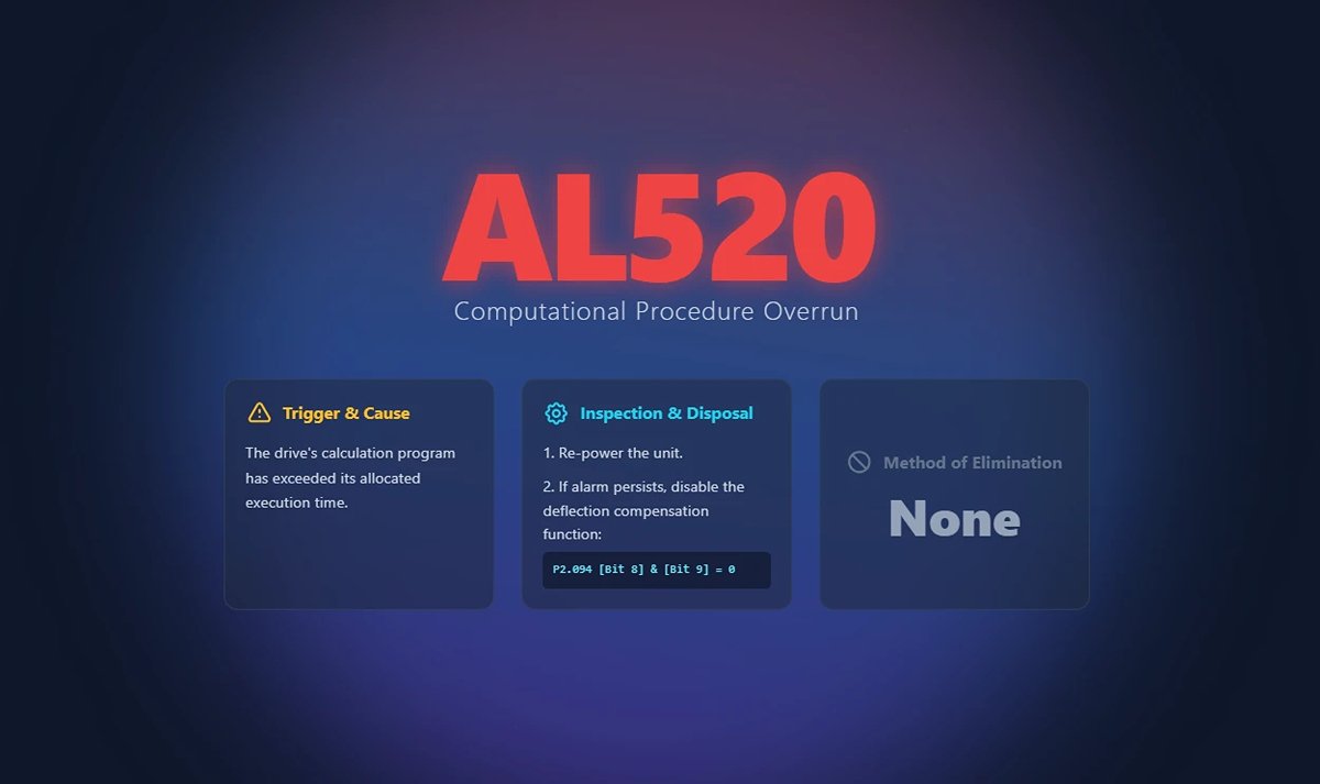
133. AL521 Flexural Compensation Parameter Anomaly
(1) Trigger conditions and causes of abnormal alarms
Condition: The servo judges that the value of the input deflection compensation parameter is not reasonable.
Cause:
- The user manually entered an unreasonable value for the deflection compensation parameter.
- The operating system analyzes the program for other variables that cause the baud graph to be abnormal.
(2) Inspection and disposal
Re-execute the system analysis and set the deflection compensation parameters.
(3) Methods of elimination
- Re-execute the system analysis and set the deflection compensation parameters.
- If it still does not release, turn off the deflection compensation function (P2.094 [Bit 8] & [Bit 9] = 0).
134. AL555 System Failure
(1) Trigger conditions and causes of abnormal alarms
Drive processor exception.
(2) Inspection and disposal
If AL555 occurs, do not make any changes to the original machine, please return it directly to the factory.
(3) Methods of elimination
None.
135. AL809 PR Basic Action Setting or Command Decoding Error
(1) Trigger conditions and causes of abnormal alarms
Condition: A command decoding exception occurred in the driver Motion execution.
Cause: The PR internal program may have generated an error due to a command error or software compilation exception.
(2) Inspection and disposal
- If this alarm occurs in non-PR control mode, store the current parameter file and provide it to your dealer.
- If you are an advanced user, please capture the oscillogram when the alarm occurs, set the channel to capture P5.007 and P0.001, and store the waveform.
(3) Methods of elimination
Re-energize to clear.
Ⅲ. Standardized Diagnostic Framework
1. Pre-Diagnosis Preparation: Safety Protocols (LOTO) and Essential Tool Kit
Before touching any hardware, thorough preparation is what separates professionals from amateurs. Rushing in is the breeding ground for both safety incidents and diagnostic mistakes. Our diagnostic process begins with uncompromising safety and a fully equipped toolset.
(1) Safety First: Power Down, Verify, Discharge, Lock and Tag — Standard Procedure
Servo systems are high-voltage “beasts.” The DC bus capacitors inside a drive can retain lethal voltages even after power is switched off. That’s why LOTO (Lockout/Tagout) isn’t just a regulation—it’s your non-negotiable lifeline. Always follow these four steps:
1) Power Off: Decisively shut down both the main supply and control power to the servo driver, and lock them in the OFF position.
2) Verify De-energization: Using a properly calibrated multimeter, check the driver’s main circuit terminals (L1, L2, L3) and the DC bus terminals (P, N) multiple times to ensure voltage has dropped to a safe level (typically below 5V). Never rely solely on indicator lights or software status.
3) Discharge Capacitors: Even when the meter reads zero, wait at least 5–10 minutes (consult the equipment manual for exact timings) to allow internal capacitors to fully discharge through bleed resistors. This is a critical but often overlooked step.
4) Lock and Tag: Attach your personal ID tag to the lock, clearly stating: “Under Maintenance—Do Not Energize.” This protects not just you, but also your colleagues and the equipment.

(2) Hardware Tool Kit
1) Multimeter
The absolute basic tool—your “stethoscope.” Used to measure supply voltage, verify three-phase balance and stability; check cable continuity and shorts; detect physical damage to power or encoder cables; measure resistance in motor windings, brake resistors, and contactor coils.
2) Oscilloscope
Your “ECG monitor” for advanced diagnostics. When troubleshooting signal quality, this is the one tool that exposes elusive anomalies. Capture encoder signals to check clarity, absence of glitches, and adequate amplitude. Analyze power noise by observing ripple and disturbances on DC bus or control power. Verify analog commands to ensure speed/torque references from the host are smooth and accurate.
3) Encoder Tester
A specialist’s “truth detector.” When encoder failure is suspected, it can assess the encoder’s condition independently of the drive, reducing diagnosis time from hours to minutes.
4) Cable Tester
Especially critical for high-flex drag chain applications. Detects intermittent faults or poor contacts that only occur during motion—issues often invisible to standard multimeters.
(3) Software Tool Kit
- Servo Tuning Software: Your main control console—valuable far beyond parameter tuning. Includes powerful diagnostic features: Alarm History—view detailed logs to spot fault patterns; Real-Time Monitoring—observe live plots of speed, current, position error, and other variables; Data Trace/Black Box—the most important feature, capturing hundreds of milliseconds of data before and after a fault for root cause analysis—effectively your “flight recorder.”
- Parameter Backup & Comparison Tools: The system’s “genetic record.” Perform regular backups during normal operation. For troubleshooting, compare current settings with a “healthy” backup (using tools like Beyond Compare). Over 90% of logic-related issues stem from unauthorized or accidental parameter changes.
2. The “Three Steps × Four Layers” Integrated Diagnostic Method
(1) Three-Step Diagnostic Method
This is our strategic roadmap—the cognitive process we follow to tackle any problem.
1) Identify:
Stop grumbling about “another alarm” and start gathering on-site evidence like a detective. What’s the alarm code? (e.g., AL.24 – Encoder Communication Error). What’s the context? (e.g., Occurs at high speed? Or at power-up?). What’s the frequency or pattern? (e.g., Always on the first startup each morning? Random?). Any related symptoms? (e.g., unusual noise, smell, or vibration?).
2) Categorize:
Based on collected information, form a preliminary, logical hypothesis. For example: “AL.24 alarm occurs during high-speed motion, specifically when vibration peaks at a drag chain bend. Likely cause: feedback-layer issue—encoder cable damaged due to prolonged flexing, resulting in poor contact.”
3) Isolate:
The most critical step—validate or rule out your hypothesis by minimizing variables. For instance: “Swap the suspect axis’s encoder cable with one from a known-good axis. If the fault moves to the other axis, the cable is confirmed faulty. If not, rule out the cable and check the motor’s encoder or the drive’s interface.” Isolation testing is the only scientific safeguard against “part-swapping guesswork.”
(2) Four Diagnostic Layers
Think of this as your troubleshooting map—check from easiest to hardest, from the outside in, for maximum efficiency.
1) Power Layer: The source of all operation. Check main supply, control power, and grounding. Without stable power, all diagnostics are meaningless. Easy to check, low cost, yet often overlooked.
2) Control Layer: The system’s “brain and nerves”—including PLC/controller, the servo drive itself, and all parameter settings. Are commands correct? Are parameters reasonable? Is the drive hardware damaged?
3) Feedback Layer: The “eyes and ears” of the system—primarily encoders and their cables. Can the system accurately know what the motor is doing? Signal integrity is the key here.
4) Mechanical Layer: The “bones and muscles” of the system—motor, couplers, gearboxes, ball screws, linear guides, and load mechanics. Are there jams, poor lubrication, excessive resistance, inertia mismatches, or other physical issues?
By combining the Three-Step method with the Four-Layer approach, you have the ultimate toolkit for diagnosing any servo alarm.
Ⅳ. Conclusion
By refining our maintenance and management practices, we transition from passive reaction to proactive prevention. Servo alarms are no longer production-stopping nightmares, but simply the system’s friendly way of telling us it’s time for a routine check-up. This is the pinnacle of expert thinking—where the real goal isn’t just the ability to solve problems, but the wisdom and conditions that prevent them from arising at all.


