I. Introduction to Laser Cutting Machines
Laser cutting machines have revolutionized the metal processing industry by offering unparalleled precision and versatility. Understanding their capabilities and limitations, particularly concerning material thickness, is essential for optimizing their use and achieving high-quality end products. For readers exploring how material thickness influences machine choice, the Choose the Laser Cutting Machine Size: Expert Guide offers a comprehensive perspective on aligning machine dimensions with your application needs.
1.1 Importance of Laser Cutting Machine Thickness
The thickness of the material that a laser cutting machine can handle is a critical parameter that directly impacts its performance and suitability for specific tasks. Material thickness not only determines the type of laser required but also influences cutting speed, edge quality, and overall efficiency.
Thin materials can be cut quickly with minimal heat-affected zones, while thicker materials require more power and slower cutting speeds to maintain precision and avoid overheating.
Recognizing the importance of material thickness helps in selecting the appropriate laser cutting machine and optimizing its operational parameters for different applications.
II. Factors Affecting Laser Cutting Machine Thickness
To truly master thick-plate cutting, you must look beyond surface-level parameter comparisons and delve into the underlying physics. From laser generation to material interaction, every step holds the key to enhanced cutting capability. Understanding these driving forces is your essential bridge from equipment operator to true process expert.
2.1 The Core Engine: The Critical Role of Laser Power and Energy Density
Laser Power (measured in watts, W, or kilowatts, kW) is the most fundamental and visible indicator of cutting capability. Higher power means more total energy output per unit of time—essential for melting and penetrating thicker materials. Clearly, as power scales from 3 kW to 6 kW, 12 kW, 20 kW, and beyond, the achievable cutting thickness increases dramatically.
However, power alone doesn’t tell the whole story. Energy Density (measured in W/mm²) is the true “blade” of the laser—it reflects how tightly the energy is concentrated at the focal point and defines the beam’s sharpness. A sufficiently high energy density can instantly raise a small region of material to its melting or even boiling point, forming a deep, narrow molten pool that enables efficient cutting.
Core relationship: Energy Density ∝ Power / (Beam Spot Area)
This equation reveals a key insight: a lower-power laser with exceptional beam quality (able to focus to a smaller spot) can achieve higher energy density than a higher-power but poorly focused one—resulting in superior penetration under specific conditions. Therefore, when evaluating equipment, don’t be deceived by raw power alone. Energy density is the true driver of thick-plate cutting performance.
2.2 Technology Choices: Performance Showdown Between CO₂ and Fiber Lasers in Thick-Plate Cutting
In today’s industrial cutting field, CO₂ and fiber lasers dominate as the two primary technology routes. Their differing wavelengths lead to distinct material interactions, which directly determine their suitability for thick-plate applications.
To compare how each performs with metals like aluminum and copper, refer to the Guide to Laser Cutting Metals.
| Feature Comparison | Fiber Laser | CO₂ Laser |
|---|---|---|
| Key Strengths | High absorption efficiency, fast thin-sheet cutting, minimal maintenance | Stable beam quality, outstanding for nonmetals, excellent edge quality on thick carbon steel |
| Wavelength | ~1.06 µm | ~10.6 µm |
| Thick Metal Cutting | The industry’s mainstay. Its wavelength is absorbed 3–10× more effectively by metals, offering a major advantage with reflective materials like aluminum and copper. Ultra-high-power (20 kW+) fiber lasers can now commercially cut metals over 100 mm thick. | Once the king of thick-plate cutting. For carbon steel over 20 mm, its longer wavelength creates a wider kerf that aids slag removal, producing mirror-smooth edges. However, it is inefficient and risky with reflective metals. |
| Thick Nonmetal Cutting | Poor performance—most energy is reflected or transmitted. | Irreplaceable. Nonmetals such as acrylic, wood, leather, and rubber absorb its 10.6 µm wavelength extremely well, making it ideal for cutting thick acrylic (>30 mm) or heavy wood panels. |
| Technology Frontier | Beam shaping / ring-mode innovation: adjusts the beam’s energy distribution so fiber lasers can mimic CO₂’s wide-kerf advantages, greatly improving cut quality and stability on thick carbon steel. | A mature technology with fewer recent breakthroughs; market share is declining as fiber lasers rise. |
| Operating Cost | Very low. Exceptional electro-optical efficiency (>30%), low energy use, fully fiber-delivered beam path with no mirrors to maintain, and long service life. | Relatively high. Low conversion efficiency (~10%), higher energy use, ongoing mirror maintenance and gas replenishment required. |
Practical conclusion: For most metal thick-plate applications (carbon steel, stainless steel, aluminum, copper), high-power fiber lasers have become the undisputed mainstream due to their efficiency, cost advantages, and broad material compatibility. CO₂ lasers, however, still retain a niche for ultra-thick carbon steel demanding superior edge quality and thick nonmetal materials, where their unique traits remain unmatched.
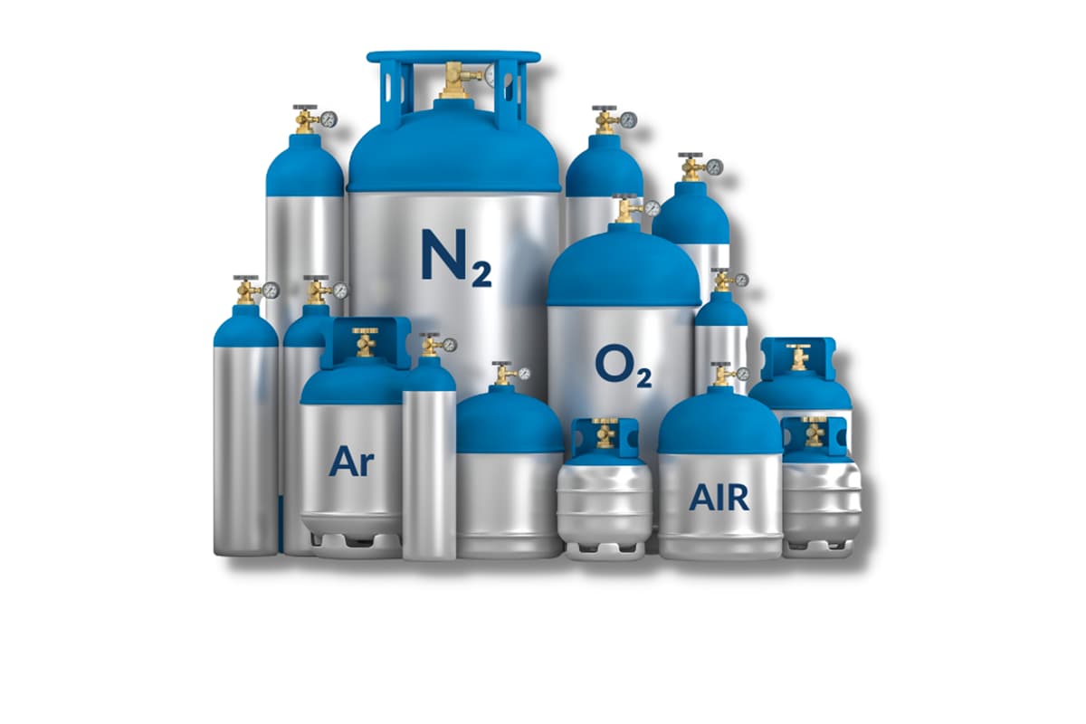
2.3 Productivity Multipliers: The Role of Assist Gases (Oxygen/Nitrogen/Air) and the Art of Pressure Optimization
If the laser is the "blade," then the assist gas is the "high-pressure airflow" that drives it and clears the battlefield. It performs three crucial roles during cutting: blowing away molten material, protecting the focusing lens from contamination, and—in some cases—participating in chemical reactions that enhance cutting power.
- Oxygen (O₂) – The Energy Booster: Primarily used for cutting carbon steel. Under the intense heat of the laser, oxygen reacts violently with iron in an exothermic reaction, releasing additional chemical energy that acts as a “fuel,” amplifying the laser’s cutting capacity beyond its physical limit. This is the hidden weapon enabling lower-power systems to cut thick carbon steel—but at the cost of forming a thin oxide layer on the cut surface, which can affect weld quality.
- Nitrogen (N₂) – The Quality Guardian: As an inert gas, nitrogen doesn’t take part in any chemical reactions. Its sole role is to use high pressure and flow velocity to expel molten metal before oxidation occurs. It’s therefore ideal for cutting stainless steel and aluminum alloys, producing bright, oxide-free cuts ready for direct welding. When cutting thick plates, maintaining high nitrogen pressure and purity is critical to achieving flawless stainless-steel edge quality.
- Air – The Economical Choice: Composed of roughly 80% nitrogen and 20% oxygen, air can be generated on-site with a compressor, making it an extremely low-cost option. It provides a middle ground between oxygen and nitrogen—offering a certain level of oxidation assistance, but far less than pure oxygen. Air is suitable for thin-plate processing where surface quality requirements are moderate and cost efficiency is prioritized. For thick plates, however, its inconsistent pressure and purity limit slag removal performance, so it’s generally not recommended.
The Art of Pressure Optimization: Gas pressure is an exceptionally sensitive variable. If the pressure is too low, molten material cannot be expelled effectively, leading to severe dross formation at the bottom of the cut. If it’s too high, the excessive cooling effect reduces cutting efficiency, may round the upper edges of the kerf, and causes unnecessary gas consumption. The key is to fine-tune pressure through repeated trials—balancing material thickness, type, and cutting speed—to discover the “optimal pressure window” where speed, quality, and cost intersect harmoniously.
2.4 The Key to Precision: How the Optical System (Focal Length and Beam Quality M²) Affects Penetration Power
The optical system serves as the “sight and lens assembly” of the laser cutter, determining whether laser energy can be delivered and focused with maximum precision and efficiency.
- Beam Quality (M²): M² is the benchmark for evaluating a laser beam’s focusability. The closer its value is to 1, the higher the beam quality, the smaller the divergence angle, and the more tightly it can be focused into an intensely concentrated spot. For cutting thick materials, a high-quality beam provides a greater depth of focus—meaning less variation in beam size and energy density as it passes through the material’s thickness. This consistency yields straighter and more uniform cuts from top to bottom.
- Focal Length and Focal Position:
- Focal Length Selection: A longer focal length produces greater depth of focus, crucial for maintaining consistent cutting quality through thick materials. The trade-off is a slightly larger spot size and lower energy density. In contrast, short focal length lenses achieve ultra-small spots and very high energy density, ideal for high-speed thin-sheet cutting. Consequently, long focal length cutting heads are typically chosen for thick-plate applications.
- Focal Position Control: This is the core process secret in thick-plate cutting. The focal point is not always on the material surface. It’s usually set one-third to two-thirds below the surface when cutting thick metal. This exploits the converging and diverging behavior of the beam around the focal point to create a wider channel mid-cut, making it much easier for high-pressure assist gas to expel molten material. It’s a key technique for eliminating bottom-side dross.
2.5 The Ultimate Battlefield: How Material Properties (Reflectivity, Thermal Conductivity, Melting Point) Shape Cutting Performance
Ultimately, cutting success depends on how laser energy interacts with each specific material. Every material presents its own battlefield—its physical properties determine how easy or difficult it is to cut.
- Reflectivity: Nonferrous metals such as aluminum, copper, and brass exhibit high reflectivity at the 1.06 µm wavelength typical of fiber lasers. This means that at the initial contact, most of the laser energy is reflected rather than absorbed. Cutting these materials requires extremely high peak power and specialized piercing techniques (such as pulsed piercing) to first “break through” the reflective surface and create an entry point for energy absorption.
- Thermal Conductivity: Materials with high thermal conductivity—like pure aluminum or pure copper—are a laser cutter’s nightmare. They rapidly dissipate the heat that the laser is trying to concentrate, making it difficult to sustain the melting temperature. It’s like trying to heat a massive heat sink with a small flame. Cutting such materials demands an exceptionally high energy density so that melting and vaporization occur faster than heat can spread away.
- Melting Point, Density, and Heat of Vaporization: These factors together determine how much energy is needed to transform a unit volume of material from solid to molten and then eject it. High-melting-point, high-strength materials such as titanium alloys naturally require significantly more energy input than mild steel, making them far more challenging to cut.
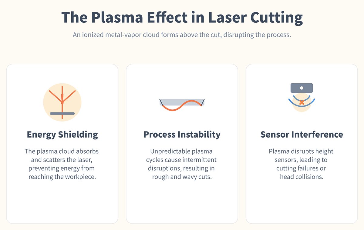
2.6 Beyond Power: The Physics of Plasma Effects and Dross Control in Thick-Plate Cutting
When laser power density reaches extreme levels—especially during thick metal cutting—a critical yet often overlooked physical phenomenon occurs: the plasma effect.
Under intense laser bombardment, vaporized metal becomes further ionized, forming a “metal-vapor plasma cloud” made up of high-temperature ions and free electrons. This cloud hovers above the cut, just below the nozzle. As spectacular as it appears, this plasma is in fact a major disruptor in the cutting process:
- Energy Shielding: The plasma cloud absorbs and scatters subsequent laser beams, acting like an opaque “energy shield” that prevents power from reaching the lower regions of the workpiece. This dramatically reduces energy transmission efficiency, undermining cutting performance—especially deep within the kerf, where energy attenuation is most severe.
- Process Instability: The formation and dissipation of plasma occur cyclically and unpredictably, causing intermittent disruptions in the cutting process. The result is a rough, wavy surface pattern on the cut edge, severely compromising quality.
- Sensor Interference: The plasma cloud alters the capacitive field between the nozzle and the workpiece, disrupting the function of capacitive height sensors. This can cause the cutting head to misread height (commonly known as “jumping”), increasing the risk of cutting failure or head collision.
Controlling plasma is the root of controlling dross formation. Dross consists of re-solidified molten metal that the assist gas failed to expel completely. The plasma shielding effect reduces energy at the kerf bottom, which is the fundamental cause of dross. Thus, mastering thick-plate cutting is essentially an exercise in precise plasma management:
- Optimize Gas Flow Dynamics: The most direct approach is to use strong, well-optimized laminar or turbulent gas flow to forcibly blow out metal vapor and molten material before a large plasma zone can form. This not only reduces plasma shielding but also serves as the primary means of removing dross. Fine-tuning nozzle type, orifice diameter, and standoff distance is crucial.
- Adjust Process Parameters: Moderately reducing cutting speed lowers the rate of metal vaporization, thereby reducing plasma concentration. Employing pulsed rather than continuous laser output allows plasma to dissipate between pulses—another effective countermeasure.
- Adopt Advanced Techniques: Using technologies such as wobble heads—which oscillate or spiral the beam at high frequency—can intentionally disturb the molten pool and gas flow, disrupting plasma stability. This is a cutting-edge method for mitigating the plasma effect.
Mastering thick-plate cutting is not just about delivering raw power. It’s about skillfully managing complex phenomena—like plasma formation and energy transfer—so every watt of energy is applied precisely and efficiently to the “cutting edge.” Mastery over plasma and dross behavior is what truly separates a skilled operator from a genuine process expert.
III. Comparing Laser Cutting Thickness Across Materials
3.1 Types of Lasers
- CO2 Lasers: Commonly used in industries such as signage, woodworking, and manufacturing, CO2 lasers are ideal for cutting non-metals like wood, acrylic, and plastics. They can cut relatively thick non-metal materials, up to 20 mm. However, they are less effective for cutting metals compared to fiber lasers.
- Fiber Lasers: Highly efficient for cutting metals, fiber lasers are prevalent in automotive, aerospace, and sheet metal industries. They can handle medium-thickness materials, up to 25 mm for metals like stainless steel and aluminum. They offer superior speed and lower operational costs.
- Nd:YAG Lasers: Known for high precision, Nd:YAG lasers are used in the medical device industry and for fine cutting applications. They are suitable for cutting both metals and non-metals but are generally limited to thinner materials, up to 10 mm.
| Laser Type | Strengths | Limitations |
| CO2 Lasers | Versatile for non-metals and some metals, offering high precision and quality for thicker non-metal materials. | Less effective for thicker metals due to lower absorption rates and higher maintenance requirements. Typically limited to cutting metals up to 20 mm thick. |
| Fiber Lasers | Superior for cutting metals with higher speed and efficiency. Capable of handling a wider range of thicknesses in metals, up to 25 mm. | Less effective for thicker non-metals. Fiber lasers are generally limited to cutting non-metals up to 15 mm thick. |
| Nd:YAG Lasers | High precision for fine cutting applications, suitable for both metals and non-metals. | Typically limited to thinner materials, up to 10 mm. Higher initial cost and more specialized applications. |
3.2 Typical Thickness Ranges for Different Materials
Metal
Steel (Carbon and Stainless)
Steel, including carbon and stainless steel, is one of the most commonly laser-cut metals in industrial applications.
- Maximum Thickness:
- Fiber Lasers: Up to 25 mm
- CO2 Lasers: Up to 20 mm
- Minimum Thickness:
- Both Lasers: As thin as 0.5 mm
- Characteristics:
- Carbon Steel: Easier to cut due to its lower carbon content but may require more power for thicker sheets.
- Stainless Steel: More challenging due to its higher resistance to heat and corrosion, but fiber lasers are particularly effective.
- Applications: Automotive components, construction materials, and manufacturing equipment.
- Advantages: High precision and efficiency.
- Challenges: Higher power requirements for thicker materials.
- Example: Automotive manufacturers use fiber lasers to cut precise components for car bodies, ensuring high accuracy and quality.
Aluminum
Aluminum's lightweight and corrosion-resistant properties make it a popular choice for various industries, but its reflective nature can pose challenges.
- Maximum Thickness:
- Fiber Lasers: Up to 20 mm
- CO2 Lasers: Up to 15 mm
- Minimum Thickness:
- Both Lasers: As thin as 0.5 mm
- Characteristics:
- Reflectivity: Requires careful handling with CO2 lasers to avoid beam reflection issues.
- Heat Conductivity: High thermal conductivity can dissipate heat quickly, necessitating higher power settings.
- Applications: Aerospace parts, transportation vehicles, and packaging materials.
- Advantages: Lightweight and corrosion-resistant.
- Challenges: Reflective nature can pose challenges for CO2 lasers.
- Example: Aerospace companies use laser cutting for aluminum parts in aircraft manufacturing, ensuring lightweight and durable components.
Brass and Copper
Brass and copper are highly conductive and reflective materials, presenting unique challenges for laser cutting.
- Maximum Thickness:
- Fiber Lasers: Up to 15 mm
- CO2 Lasers: Up to 10 mm
- Minimum Thickness:
- Fiber Lasers: As thin as 0.5 mm
- Characteristics:
- Reflectivity: Significant reflectivity requires special coatings or fiber lasers to manage the laser beam effectively.
- Conductivity: Excellent electrical conductivity, making them ideal for electrical components.
- Applications: Electrical connectors, plumbing fixtures, and decorative items.
- Advantages: Excellent electrical conductivity.
- Challenges: Reflectivity requires careful handling.
- Example: Electronic manufacturers use laser cutting for precise copper components in circuit boards.

Titanium
Titanium is valued for its high strength-to-weight ratio and corrosion resistance, making it suitable for high-performance applications.
- Maximum Thickness:
- Fiber Lasers: Up to 20 mm
- Minimum Thickness:
- Fiber Lasers: As thin as 0.5 mm
- Characteristics:
- Strength: High strength requires robust laser systems to ensure clean cuts, especially for thicker sections.
- Cost: Expensive material, necessitating efficient cutting processes to minimize waste.
- Applications: Aerospace components, medical devices, and high-performance sports equipment.
- Advantages: High strength-to-weight ratio.
- Challenges: Expensive material.
- Example: Laser-cut titanium is used in the Mars rover, showcasing its high-performance capabilities.
Non-Metals
Acrylic
Acrylic is a widely used non-metal in industries requiring clear, aesthetically pleasing cuts.
- Maximum Thickness:
- CO2 Lasers: Up to 25 mm
- Minimum Thickness:
- CO2 Lasers: Thin as 1 mm
- Characteristics:
- Clarity: Produces clear and polished edges when cut correctly.
- Fume Generation: Cutting acrylic generates fumes, requiring effective ventilation systems.
- Applications: Signage, displays, and decorative items.
- Advantages: Clear and aesthetically pleasing cuts.
- Challenges: Can produce fumes; requires proper ventilation.
- Example: Retail stores use laser-cut acrylic for high-quality, custom signage.
Wood
Wood is a versatile material for laser cutting, used in various artistic and practical applications.
- Maximum Thickness:
- CO2 Lasers: Up to 20 mm
- Minimum Thickness:
- CO2 Lasers: Thin as 1 mm
- Characteristics:
- Versatility: Suitable for a wide range of designs, from intricate patterns to large cuts.
- Smoke and Char: Proper ventilation is necessary to manage smoke and reduce charring.
- Applications: Furniture, art, and construction materials.
- Advantages: Versatile material for various designs.
- Challenges: Requires proper ventilation due to smoke.
- Example: Artisans use laser cutting for intricate wooden art pieces and custom furniture designs.
Plastics
Plastics are commonly used in consumer goods and industrial applications, offering ease of cutting and shaping.
- Maximum Thickness:
- CO2 and Nd:YAG Lasers: Up to 10 mm
- Minimum Thickness:
- Both Lasers: Thin as 1 mm
- Characteristics:
- Melting Point: Low melting points necessitate careful power and speed adjustments to avoid warping or charring.
- Variety: Different types of plastics (e.g., PET, PVC, ABS) have unique cutting requirements.
- Applications: Consumer goods, packaging, and automotive components.
- Advantages: Lightweight and easy to shape.
- Challenges: Melting and charring if not properly managed.
- Example: Packaging companies use laser cutting for precise plastic packaging designs.
Composite Materials
Composite materials, such as carbon fiber-reinforced polymers (CFRP) and glass fiber-reinforced polymers (GFRP), combine different materials to enhance properties like strength and durability.
- Maximum Thickness:
- Fiber Lasers: Up to 20 mm
- Minimum Thickness:
- Fiber Lasers: Thin as 0.5 mm
- Characteristics:
- Variable Composition: Different layers and materials within composites require tailored cutting settings.
- Dust Generation: Cutting composites can produce fine dust, necessitating effective extraction systems.
- Applications: Aerospace structures, automotive parts, and sports equipment.
- Advantages: High strength-to-weight ratio.
- Challenges: Requires specialized settings due to variability in composition.
- Example: Sports equipment manufacturers use laser cutting for carbon fiber components in high-performance bicycles.
| Material Type | Laser Type | Max Thickness (mm) | Cutting Speed | Edge Quality |
| Wood | CO2 | 20 | Medium | High |
| Acrylic | CO2 | 25 | Medium | High |
| Stainless Steel | Fiber | 25 | High | Medium to High |
| Aluminum | Fiber | 20 | High | Medium to High |
| Brass | Fiber | 15 | High | Medium to High |
| Plastics | CO2, Nd:YAG | 10 | High | High |

IV. Techniques for Optimal Laser Cutting Machine Thickness
4.1 Adjusting Laser Settings
Power and Intensity Adjustments:
- Higher Power for Thicker Materials: Increasing the laser power allows for deeper penetration into thicker materials. For example, cutting 20 mm thick steel might require a 3000-watt laser, while 10 mm may only need 1500 watts. This ensures efficient energy usage and clean cuts.
- Lower Power for Thinner Materials: Reducing power helps in cutting thinner materials with precision, minimizing heat-affected zones and avoiding material warping. A 500-watt laser is suitable for cutting 3 mm aluminum, ensuring delicate materials are not damaged.
Cutting Speed:
- Slower Speeds for Thicker Materials: Reducing the cutting speed ensures that the laser can effectively penetrate and cut through thicker materials, enhancing edge quality. For instance, cutting 25 mm stainless steel would require a slower pace to maintain a clean cut, avoiding incomplete cuts or rough edges.
- Faster Speeds for Thinner Materials: Increasing the speed is beneficial for cutting thinner materials, improving efficiency and throughput. Thin sheets of plastic or metal can be cut rapidly without compromising precision, speeding up production times.
Focus Adjustment:
- Optimizing the Focus: Properly focusing the laser beam is crucial for achieving clean and precise cuts, especially in thicker materials. Adjusting the focal length ensures the laser energy is concentrated at the right depth, reducing the risk of defocusing and poor quality cuts.
- Automatic Focus Systems: Modern laser machines often feature automatic focus adjustment to maintain optimal focus during the cutting process, enhancing consistency and quality. This is particularly useful for varying material thicknesses within a single cutting job.
4.2 Utilizing Appropriate Assist Gases
Selecting the correct assist gas plays a critical role in managing the cutting thickness. Oxygen can be used to enhance cutting efficiency in thicker metals through exothermic reactions, while nitrogen might be preferable for stainless steel to prevent oxidation and maintain edge quality.
The pressure and flow rate of these gases should be optimized based on the material and desired cutting thickness to ensure clean and precise cuts.
4.3 Layer-by-Layer Cutting for Thicker Materials
Incremental Cutting:
- Layer-by-Layer Approach: For extremely thick materials, a layer-by-layer cutting approach can be employed. This involves making multiple passes at increasing depths, gradually cutting through the material. For example, cutting a 50 mm thick titanium block might require several passes to achieve a precise cut.
- Reduced Heat Impact: This method helps in managing heat dissipation, reducing thermal distortion and improving overall cut quality. It ensures that each layer is cut cleanly without excessive heat build-up.
Sequential Cutting:
- Sequential Cuts: Breaking down the cutting process into sequential steps can enhance precision and quality, especially for complex shapes and thick materials. This technique allows for more controlled and accurate cuts.
- Adaptive Strategies: Using adaptive cutting strategies where the machine adjusts power and speed dynamically based on material thickness can optimize the cutting process, ensuring consistent results across varying thicknesses.
4.4 Advanced Techniques and Innovations
Dynamic Beam Shaping:
- Adapting Beam Shape: Advanced laser systems can dynamically adjust the beam shape to optimize cutting for different thicknesses. This allows for precise control over the cutting process, enhancing edge quality and consistency. For instance, adjusting the beam shape to a wider profile can improve cutting efficiency for thicker materials.
- Real-World Example: In industrial applications, dynamic beam shaping can be used to cut complex geometries in thick materials like aerospace-grade alloys, ensuring high precision and minimal material waste.
Automated Thickness Adjustments:
- Integration with Software: Modern laser cutting machines often integrate with advanced software that can automatically adjust settings based on material thickness. This reduces setup time and ensures optimal performance. Software can provide real-time feedback and adjustments, improving cutting accuracy.
- Real-Time Monitoring: Using sensors and AI, real-time monitoring systems can adjust laser settings on-the-fly, compensating for variations in material thickness and ensuring consistent quality. This technology is particularly useful in high-volume manufacturing environments.
4.5 Practical Tips for Operators
Regular Calibration:
- Ensuring Accuracy: Regularly calibrating the laser cutting machine ensures that it operates at peak performance, maintaining precise focus and alignment. Calibration should be part of routine maintenance to prevent deviations that can affect cutting quality.
- Preventive Maintenance: Implementing a preventive maintenance schedule helps in identifying and addressing potential issues before they affect cutting quality. This includes checking optics, cleaning components, and ensuring all systems are functioning correctly.
Material Preparation:
- Prepping Materials: Properly preparing materials, such as cleaning surfaces and ensuring flatness, can significantly impact the quality of the cut, especially in thicker materials. Removing contaminants and ensuring a smooth surface can improve laser efficiency.
- Fixture Design: Using appropriate fixtures to hold materials securely can reduce vibrations and movement during cutting, improving precision. Custom fixtures can be designed for specific shapes and materials, enhancing stability and accuracy.
Ⅴ. Decision Framework: A Five-Step Method for Selecting the Right Laser Cutter for Your Thickness Requirements
Choosing a laser cutting machine is a cornerstone investment in your company’s future productivity—a strategic decision that reaches far beyond a simple equipment purchase. A hasty choice can lead not only to wasted capital but also to persistent production bottlenecks, high operating costs, and missed market opportunities.
Move beyond guesswork and persuasive sales pitches. This rigorous five-step decision framework will guide you through marketing noise and parameter confusion, enabling you to select a laser cutter like a seasoned strategist—one that meets today’s requirements and supports tomorrow’s growth.
5.1 Step 1: Define Your Material and Thickness Profile—Identify the “80/20” Combination that Drives Your Business
Before diving into comparisons of machine models and power levels, the most crucial step is introspection: clearly and quantitatively define your own production needs. The pursuit of an all-powerful machine is one of the most common investment pitfalls. True intelligence lies in focusing precisely on the 20% of core tasks that generate 80% of your business value.
Quantify Core Business Composition:
Review your order history and business forecasts to create a data table listing:
- Primary Materials: What are the three materials you cut most frequently? (e.g., Q235 carbon steel, 304 stainless steel, 6061 aluminum alloy)
- Optimal Thickness Range: For each main material, what thickness range is most common? (e.g., carbon steel typically 8–16 mm; stainless steel 3–6 mm)
- Business Share: Assign an approximate percentage of total production time to each “material-thickness” combination.
Identify “Profit Engines” and “Opportunity Orders”: Your needs profile must distinguish between two kinds of tasks:
- Profit Engines (Essential Line): These are the core tasks you must perform efficiently, with high quality and low cost—for example, “consistently cutting 12 mm carbon steel with a daily output of no less than XX pieces.” For these tasks, machine performance, speed, and stability are non-negotiable.
- Opportunity Orders (Growth Line): These are occasional jobs taken on to expand your market reach or satisfy special customer requests. For example, “occasionally cutting a 30mm stainless steel plate.” For such tasks, slower cutting speeds or multiple passes are acceptable—you shouldn’t use them as a primary basis for equipment selection.

Once you complete this demand profile, you’ll have a reliable yardstick for comparing all candidate machines. It helps you avoid overpaying for extreme capabilities that you might only use a few times a year, saving unnecessary equipment premiums and ongoing operating costs.
5.2 Step Two: Power Calculation – Eliminate Guesswork with Data-Driven Power Estimation for Real Speed and Quality
Choosing the right power shouldn’t stop at the tempting “maximum cutting thickness” advertised in brochures. The power that truly matters to your business must align closely with your genuine expectations for production efficiency and delivery quality.
Build a Basic Speed Model:
Using your “Profit Engine” task (e.g., cutting 12mm carbon steel) as the benchmark, request detailed “power–material–thickness–speed” comparison charts from at least three reputable suppliers. This is not just a diagram—it’s the core dataset for your calculations.
Define Your Efficiency–Quality Baseline:
Clearly answer the following:
- Efficiency Target: For 12mm carbon steel, what is your minimum acceptable commercial cutting speed? (For instance, ≥2.0 meters/min to meet delivery deadlines.)
- Quality Standard: What surface quality do you require? (For instance, surface roughness Ra ≤ 25μm, minimal and easily removed slag.)
Back-Calculate “Effective Power” Instead of “Maximum Power”:
Use your efficiency–quality baseline as the reference point for reverse lookup in the data chart.
- If a 3kW laser cuts 12mm carbon steel at only 0.8 meters/min, it fails your efficiency requirement—thus, 3kW is ineffective for your needs.
- If a 6kW laser achieves 2.2 meters/min with the required quality, while a 12kW model reaches 4.5 meters/min, then 6kW is the starting point of your “effective power.”
Build in a “Power Safety Margin”:
Like people, machines deteriorate when pushed to their limits for extended periods. Based on your calculated “effective power,” it is strongly recommended to add 20–30% extra power capacity. This investment provides:
- Long-Term Stability: It cushions against performance fluctuations caused by optical degradation, lens aging, or variations in material batches.
- Process Flexibility: Enables you to temporarily boost power for faster production when handling urgent orders.
- Future Adaptability: Provides headroom for cutting thicker or more challenging materials in the future.
A machine that operates daily at roughly 70% of its capacity will far outlast one that constantly runs in “full-throttle” mode.
5.3 Step Three: System Evaluation – [Insight 2] Decoding the Hidden Messages Behind Technical Specifications
Two machines both labeled “12kW” can differ dramatically in actual performance and value. True experts know how to read between the lines of the specification sheet—to spot the subtle cues that manufacturers often prefer not to highlight. Those hidden details ultimately define long-term performance and return on investment.
- Laser Source Deep Characteristics: Continuous/Pulsed Power and Beam Quality (M²)
- Power Mode: A top-tier laser isn’t just about its Continuous Wave (CW) output—which determines speed and efficiency for thin-sheet cutting—but also its pulse capabilities, especially peak pulse power. Strong pulse performance is crucial for efficient, stable perforation of thick plates, delivering short bursts of high energy that minimize heat impact and drastically reduce piercing time.
- Beam Quality (M²): This is the most critical yet frequently overlooked parameter in laser specifications. M² measures the beam’s focusability—the closer its value is to 1, the better the beam quality, energy concentration, and focal depth. At equal power levels, lasers with superior M² values deliver noticeably better penetration, speed, and edge verticality when cutting thick materials.
- Hidden Message: Don’t just ask “how many watts?”—always request and compare the M² values across different brands. A transparent manufacturer will share beam quality data at high power output; those who avoid the question likely made compromises. For thick-plate cutting, beam quality can be more decisive than sheer wattage.

- Machine Tool “Skeleton and Nerves”: Bedframe Structure and Motion Control Precision
- Bedframe: The machine’s structural backbone supports all precision and stability. The immense acceleration and vibration from thick-plate cutting severely test this foundation. A monolithic cast structure (e.g., cast iron) or thick-plate welded frame undergoing thorough annealing heat treatment ensures accuracy retention over 5–10 years. Lightweight, thin-sheet welded frames will almost inevitably deform over time.
- Motion Control System: This is the machine’s neural network.
- Drive Motors: High-end industrial machines must use full closed-loop servo motors, delivering unmatched acceleration, deceleration, and positioning precision—essential for high-speed cutting of complex designs with zero dimensional error. Any thick-plate cutting solution still relying on stepper motors should be ruled out immediately.
- Transmission Mechanism: High-precision gear and rack systems are mainstream, but pay attention to their accuracy grade (such as Germany’s ALPHA brand) and installation quality. At the top tier, linear motor drives eliminate mechanical backlash entirely, offering exceptional dynamic response and contour precision—an ultimate option for precision manufacturing.
- Hidden Message: Request and compare the machine’s positioning accuracy and repeatability figures (e.g., ±0.02mm and ±0.01mm). Ask about bedframe weight and construction process. A solid, heavy frame is a silent declaration of quality. These “invisible” manufacturing costs will yield visible returns in part accuracy and machine longevity.
5.4 Step Four: Field Validation – Design an “Extreme Test” Plan and Let Real Data Speak
Never make decisions based solely on brochures or verbal claims from sales representatives. Conduct an on-site live demo (Live Demo) under your strictest standards, using your most demanding materials. This is the only way to make the right choice.
Prepare Test Materials Thoroughly:
Reject the supplier’s polished “showcase samples.” Bring materials from your own warehouse—those that best represent real conditions, even imperfect ones: slightly rusted, uneven surfaces, or plates from specific suppliers. Only then will the test reflect genuine production reality.
Design Your “Torture Test Card”:
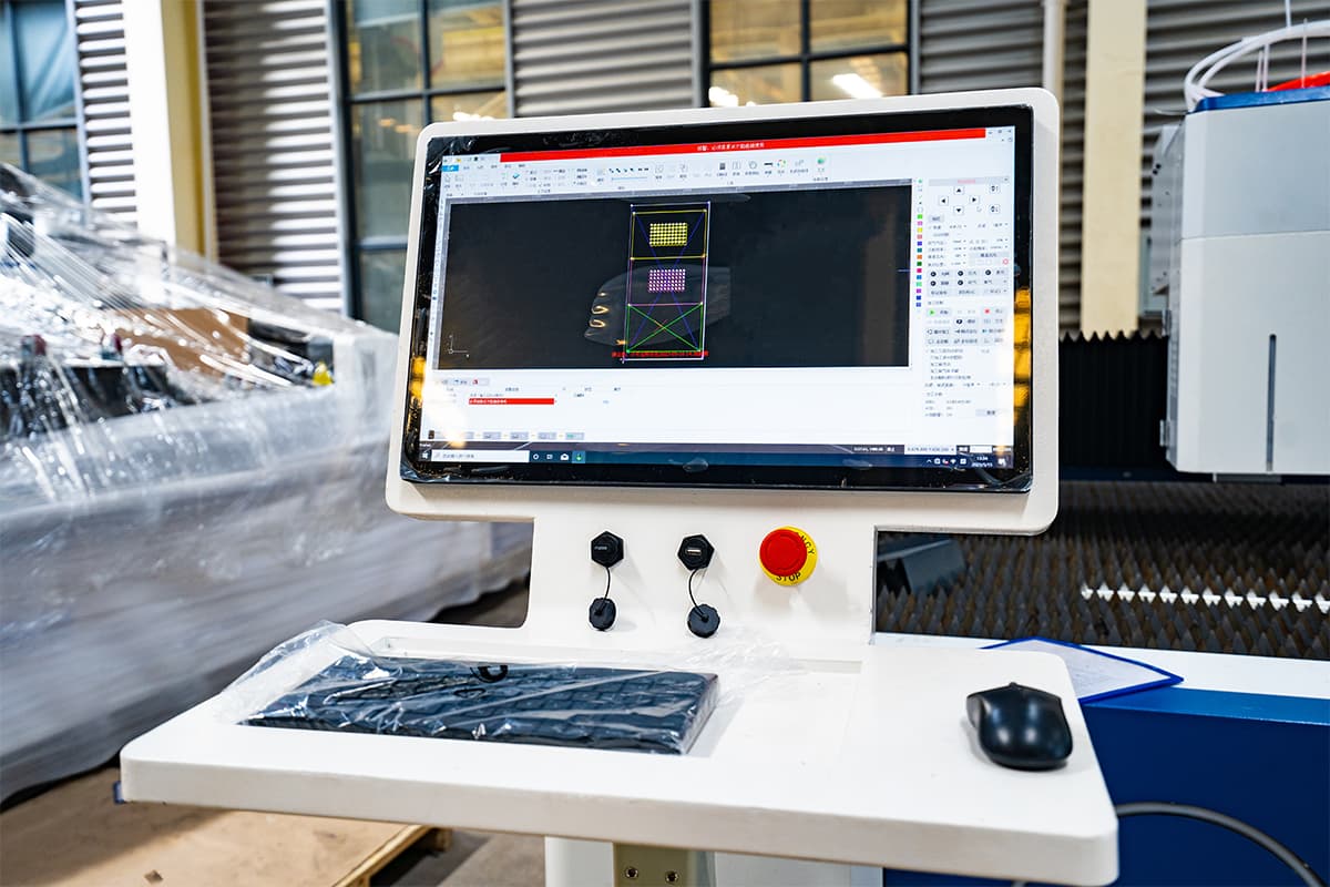
Using CAD software, create a comprehensive test file that includes the following elements. This will push the machine to its limits and reveal its true capabilities:
- Parameter Matrix: On a single sheet of metal, cut a grid of identical small squares. Assign each column an incremental cutting speed, and each row a different gas pressure or focal position. This allows you to visually pinpoint, in the shortest time, the optimal balance among speed, quality, and parameter settings.
- Sharp Angles and Microhole Arrays: Include angles ranging from 30° to 90°, as well as small, densely distributed holes from 1.0mm to 10mm in diameter. These features push the machine’s limits in corner overburn control, dynamic response, and micro-feature precision.
- Long Straight Lines and S-Curves: Use these to evaluate long-distance cutting power stability, surface consistency, and contour-following accuracy for complex shapes.
Rely on Quantitative Metrics, Not Gut Feelings:
Once cutting is completed, take on the role of a quality inspector. Use calipers, microscopes, and—if available—a surface roughness tester to perform a detailed, data-backed evaluation. Record your findings in a standardized scoring sheet:
- Effective Speed (m/min): The maximum cutting speed achievable while still meeting your quality standards.
- Cross-Section Quality: Measure the width of the cut at the top, middle, and bottom using calipers to calculate taper. Visually inspect the roughness and grain pattern of the surface.
- Dross Formation: Is the bottom-edge dross hard and brittle, or soft and easy to remove? Can it be eliminated without secondary grinding?
- Piercing Quality and Time (s): Does the piercing process on thick plates proceed smoothly? How large is the heat-affected zone around the piercing point?
Place “Torture Test Card” samples from different suppliers side by side on the conference table. Strengths and weaknesses will become immediately apparent—let the data guide you toward the most objective conclusion.
5.5 Step Five: Cost Modeling — [Insight #3] Build a Full Lifecycle Cost Model, Not Just an Upfront Budget
Savvy investors focus on Total Cost of Ownership (TCO) rather than the purchase price alone. A machine that seems 10% cheaper at acquisition might, over five years, erode your profits through higher electricity bills, gas consumption, and frequent repairs.
Before making your final decision, take one hour to build a simplified TCO model for your preferred machine:
TCO (5 years) = Initial Investment + (Annual Operating Cost × 5) − Estimated 5-Year Residual Value
- A. Initial Investment
- Equipment purchase price (including taxes)
- Transportation, lifting, installation, and commissioning expenses
- Infrastructure modifications (foundation, dedicated electrical circuits, gas lines)
- Initial training costs for operators and maintenance personnel
- B. Annual Operating Costs
- Electricity Costs: One of the largest variables. Request the machine’s rated and average power consumption from the supplier. Compare the electro-optical conversion efficiency across laser sources—every percentage point of improvement translates into long-term savings.
- Assist Gas Costs: Based on your main process (oxygen or high-pressure nitrogen) and average daily usage hours, calculate the yearly gas expense. High-pressure nitrogen represents a major cost driver, and differences in gas optimization among machines can lead to substantial savings.
- Consumables and Wear Parts: List expected replacement cycles and unit prices for key wear parts such as protective lenses, nozzles, and ceramic rings, then compute the annual total. Ask whether these are standard parts available from multiple sources or proprietary components restricted to the OEM.
- Maintenance and Repair Costs: Obtain quotes for the manufacturer’s annual maintenance contract. Even without a contract, allocate an annual maintenance reserve of approximately 3–5% of the equipment’s purchase price.
- C. Estimated Residual Value
- Estimate the resale value of the machine after five or seven years of use. Leading brands with solid maintenance histories tend to retain far higher market value than off-brand or low-end models.

Compare the TCO models of several candidate machines side by side. You may be surprised to discover that a machine costing 15% more upfront—thanks to higher efficiency, more durable components, and stronger brand reliability—can ultimately deliver the lowest total ownership cost over five years. That’s what true value for money looks like: a CEO-level decision made with a long-term strategic vision.
Ⅵ. Performance Breakthrough: Optimizing, Controlling, and Troubleshooting Thick-Plate Cutting
Owning a top-tier machine is like wielding a legendary sword—but unleashing its full potential depends on the skill of the swordsman. Now that you understand the underlying principles and have made a wise investment, it’s time to move into real-world execution. This chapter focuses on how to push your equipment to its limits through precision parameter tuning, rigorous quality control, and systematic troubleshooting—ensuring every thick plate is transformed into a commercially perfect workpiece.
6.1 Parameter Optimization Matrix: The Art of Coordinated Adjustment of Power, Speed, Gas Pressure, and Focus
Optimizing parameters for thick-plate cutting is not about tweaking numbers in isolation—it’s about mastering the dynamic balance among four core variables: power, speed, gas pressure, and focus. Blind trial and error wastes time and materials. A skilled process engineer applies a systematic “parameter optimization matrix” approach to efficiently pinpoint the best settings.
Its foundation lies in the controlled variable method:
- Establish a Baseline and Lock Variables: Start with the manufacturer’s recommended parameters or the best-performing settings from your past experience. Initially, lock gas pressure and focal position.
- Build a Speed–Power Matrix: On a test plate, create a grid where the X-axis represents cutting speed (e.g., 1.5 m/min to 3.0 m/min in 0.3 m/min increments) and the Y-axis represents laser power (e.g., 80% to 100% in 5% increments). Run this test sequence to generate a visual “map” showing exactly where clean cuts are achieved at various power levels.
- Optimize the “Cost–Quality” Variable: Gas Pressure: From the previous matrix, select a top-performing speed–power pair (for example, 95% power at 2.4 m/min for optimal edge quality). Keep these constant and begin fine-tuning the gas pressure. Adjust it in small steps—say, 0.2 Bar increments—above and below the recommended value, observing dross behavior at the bottom edge. Your goal is to identify the sweet spot where molten residue is efficiently cleared using the lowest possible pressure. This directly influences operational costs, especially when working with costly nitrogen gas.
- Fine-tuning the “Precision–Profile” Variable: Focus Position — Once the speed, power, and gas pressure are nearly optimized, proceed to the final stage: precise adjustment of the focal position. Move the focus up or down from the recommended level in increments of 0.5 mm. Observe and use calipers to measure the taper and kerf width of the cut.
- For thick carbon steel: A slightly positive focus (above the surface) facilitates faster ignition.
- For thick stainless steel: A slightly negative focus (below the surface) helps expel molten material from the bottom.
- The goal is to pinpoint the focus position that delivers the most consistent top and bottom widths and the highest perpendicularity of the cut edges.
This process may seem tedious, but the customized parameter database it builds for your core production tasks is an invaluable asset—one that no generic chart can ever replace.
6.2 Advanced Cutting Strategies
When standard methods reach their limits or you’re working with challenging materials and extreme thicknesses, true experts turn to their arsenal of advanced cutting techniques.
6.2.1 Multi-pass Cutting: When to Use It and How to Optimize Layering
When cutting through thick plates in a single pass requires extremely slow speeds and excessive heat input—causing severe edge burning, deformation, or stubborn dross buildup—multi-pass cutting becomes a smarter, more refined solution.
- Key Applications:
- Protecting Heat-Sensitive Materials: For materials highly sensitive to heat—such as thick wood, plywood, or certain laminated plastics—multi-pass cutting prevents over-charring or delamination from a single high-heat pass.
- Extending Machine Capability: Allows you to exceed the rated single-pass capacity of limited-power equipment—an especially practical approach when working under budget constraints while expanding your cutting range.
- Pursuing Ultimate Quality: When near-perfect cut surfaces are required and time is not a priority, multi-pass cutting minimizes the heat-affected zone and surface striations.
- Layering Optimization Methods:
- Rethink Cutting Logic: The principle is to replace a single slow, high-power “burn” with several fast, mid-power “scrapes.” For instance, instead of cutting through 30 mm acrylic at 10% speed and 100% power in one go, try cutting at 40% speed and 80% power for 3–4 passes, each penetrating 7–10 mm.
- Follow the Cutting Focus Layer by Layer: To keep the laser’s energy precisely concentrated at the cutting front, the ideal technique is to have the Z-axis automatically lower by one layer thickness after each pass—maintaining the focus just below the surface of the current cut. Many advanced CNC systems support this layered cutting feature.
- Manage Airflow and Debris Removal: During multi-pass cutting, ensure the assist gas flow is sufficient to clear away debris and fumes after each pass. Residual material in the kerf can interfere with laser absorption in subsequent cuts.
6.2.2 Piercing Techniques: Pulse, Progressive, and Frog-Leap Methods for Thick Plates
When cutting thick plates, piercing is often more demanding—and more critical—than the cutting itself. A poor-quality pierce can leave an irreversible blemish on the workpiece and contaminate the subsequent cutting path.
- Pulse Piercing: The standard advanced method for cutting thick metal plates (especially over 10 mm). Instead of continuous laser “drilling,” it uses a sequence of ultra-short (millisecond-level) high-peak-power pulses to vaporize and eject the material layer by layer—much like the tapping motion of a woodpecker.
- Advantages: Compared with traditional blast-piercing, pulse piercing generates a minimal heat-affected zone, greatly reduces spatter, and produces clean, round holes that set the stage for high-quality cutting that follows.
- Progressive Piercing (Power-Ramped Piercing): This method begins at a lower, safe power level and then gradually or stepwise increases to full power over a preset time (e.g., 0.5 seconds) until complete penetration is achieved.
- Advantages: This gentler approach minimizes spatter from sudden high-power surges, making it especially suitable for stainless steel and aluminum where surface appearance is critical.
- Frog-Leap / Fly Cutting: Though not a piercing technique per se, this is a revolutionary motion control method. After finishing a contour or a pierce, the cutting head rapidly lifts to a minimal safe height, then “leaps” to the next cutting point and drops back down—all at high acceleration.
- Advantages: This dramatically reduces idle travel time between cuts. For sheets with dense hole patterns or numerous small parts, it can boost overall productivity by more than 30%, making it a powerful tool for maximizing output per unit area.
6.3 The Quality Control Playbook
Outstanding quality never happens by chance—it is the inevitable outcome of a rigorous system. Integrating quality control into every step of production is the path that transforms a workshop into a precision manufacturer.
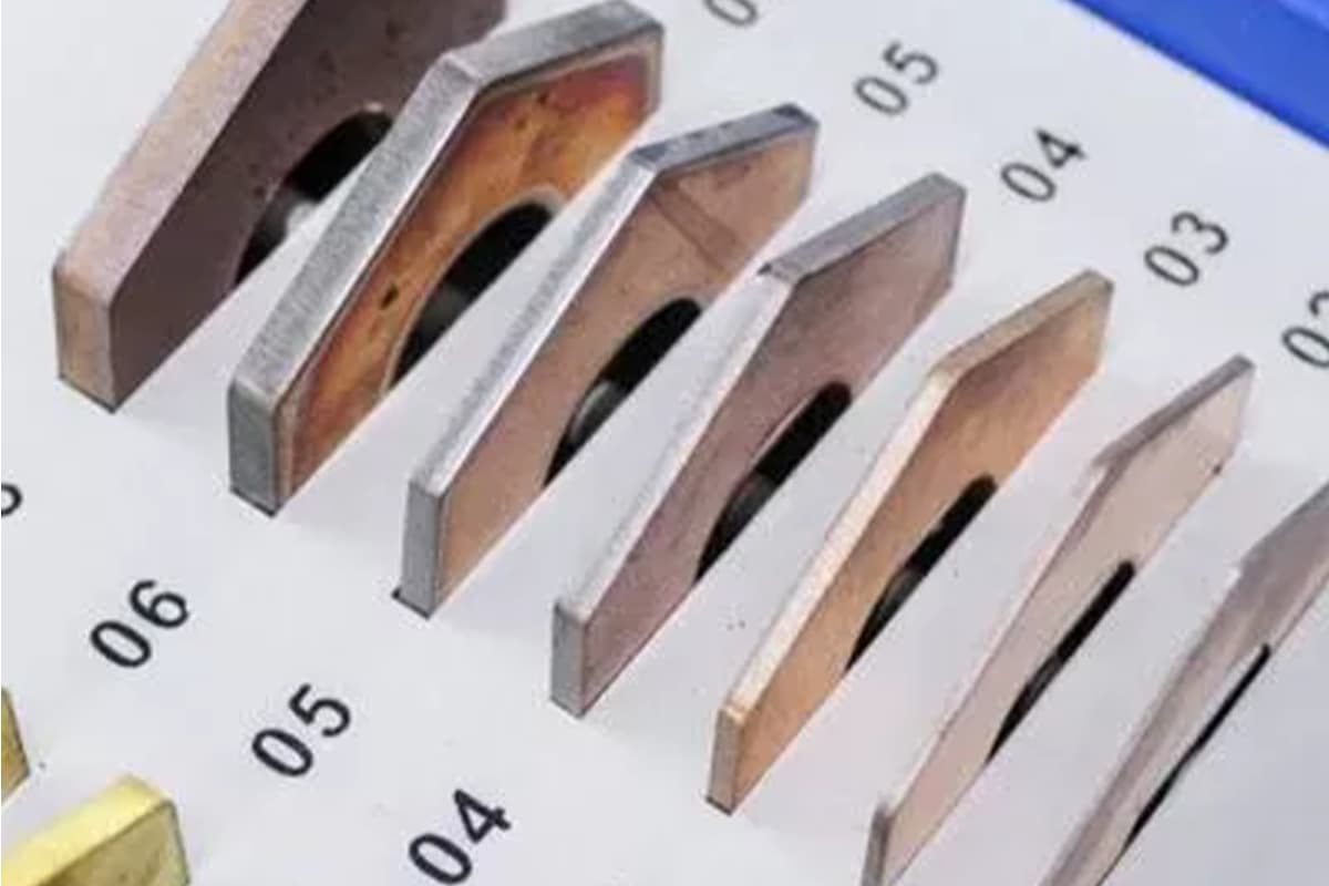
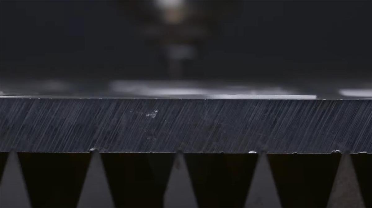
6.3.1 Common Defect Diagnostics: Causes and Remedies for Dross, Taper, and Rough Surfaces
| Defect Type | Visual Characteristics | Primary Causes | Solutions |
|---|---|---|---|
| Bottom Dross | Bead-like or flake-shaped resolidified metal adheres to the underside of the cut, difficult to remove. | 1. Insufficient gas kinetics: assist gas pressure or flow too low to fully blow the molten material away. 2. Thermal imbalance: cutting speed too fast, material not fully penetrated; or too slow, generating excessive molten metal. 3. Dispersed focal energy: improper focal position causing insufficient energy density at the bottom of the cut. | 1. Increase assist gas pressure (in 0.1 Bar increments). 2. Optimize speed—try reducing by 5–10% first. 3. Lower the focal position, typically set at about two-thirds of material thickness or slightly below. 4. Inspect and replace worn or clogged nozzles. |
| Excessive Taper | The cut appears “V”-shaped (wide top, narrow bottom) or inverted “V” (narrow top, wide bottom) instead of being perpendicular. | 1. Incorrect focal position—too high or too low is the main cause. 2. Excessive speed—beam moves before energy fully acts at the lower edge. 3. Poor beam quality—high divergence angle and short focal depth. | 1. Precisely adjust focal position—determine the position that yields optimal verticality. 2. Slightly reduce cutting speed to allow sufficient energy application. 3. If taper persists long-term, consider replacing with a lens of longer focal length to increase focal depth. |
| Rough / Grooved Cut Surface | Vertical, uneven, wavy striations appear instead of fine and smooth slanted lines. | 1. Process instability—mismatch between speed and power causes inconsistent molten pool behavior. 2. Airflow disturbance—impure or turbulent assist gas flow. 3. Mechanical vibration—subtle oscillations during high-speed table movement. | 1. Fine-tune speed and power; often lowering speed yields a smoother surface. 2. Check gas purity; optimize nozzle design and gas pressure. 3. Verify guideway lubrication and gear–rack alignment to eliminate vibration sources. |
6.3.2 [Insight #4] Acceptance Criteria: Establish Verticality and Roughness Tolerances for Different Material Thicknesses
There are no universally enforced laser cutting tolerance standards—quality levels vary greatly between top-tier manufacturers and small workshops. Therefore, developing internal, quantifiable, and documented acceptance standards is a vital step toward professionalized production and solid market reputation. It signifies a transition from subjective “looks good enough” judgments to quantifiable, traceable, and accountable scientific management.
Your in-house standards should at least cover the following parameters, categorized by material and thickness:
- Perpendicularity / Taper Tolerance:
- Example Standard:
- 1–10mm stainless steel: taper angle < 0.8°
- 10–20mm carbon steel: taper angle < 1.2°
- Measurement Method: Use a high-precision protractor or accurately measure the top and bottom kerf widths with calipers, then calculate taper using trigonometric formulas.
- Example Standard:
- Surface Roughness (Ra):
- Example Standard:
- Standard structural parts (non-mating surfaces): Ra < 25 μm
- High-precision mating or aesthetic components: Ra < 12.5 μm
- Measurement Method: Perform systematic sampling using a portable surface roughness tester.
- Example Standard:
- Dimensional Tolerance:
- Example Standard: For industrial-grade fiber laser cutters, a responsible tolerance commitment typically is:
- Profile dimension L ≤ 500mm: ±0.1mm
- Profile dimension L > 500mm: ±(0.1 + 0.0002 × L) mm
- Example Standard: For industrial-grade fiber laser cutters, a responsible tolerance commitment typically is:

Document these standards and apply them consistently for both operator self-checks and final inspections by QC personnel. When communicating with clients, this transforms “high quality” from a vague marketing slogan into a data-backed, trustworthy promise.
6.4 The Ultimate Troubleshooting Guide: Why Your Machine Can't Cut Its Rated Thickness
Few situations frustrate operators more than discovering their machine can no longer pierce materials it should easily handle. Before suspecting costly laser power degradation, remember this golden rule: Over 90% of “incomplete cut” issues stem from optical path, gas supply, or parameter settings—not the laser source itself.
Grab this ultimate diagnostic checklist and approach the task systematically—just like an experienced doctor examining every potential cause.
6.4.1 Diagnostic Checklist: Systematic Inspection from Optics and Lens Contamination to Gas Purity
| Inspection Category | Inspection Item | Key Questions (Check in this order) |
| Optical System (The #1 Culprit) | 1. Protective Lens | (Highest priority!) Remove the protective lens and inspect under proper lighting—any fogging, burn marks, or contamination? This is the most common source of malfunction. |
| 2. Internal Cutting Head Lenses | In a clean environment, check upper protective lens, collimating lens, and focusing lens for contamination. | |
| 3. Beam Alignment | Using tape test—does the laser beam exit precisely from the nozzle center? At the four corners of the worktable, is beam alignment consistent? | |
| Auxiliary System (The Enabler) | 4. Nozzle Condition | Is the nozzle diameter correct? Any deformation, clogging, or slag buildup inside? |
| 5. Gas Pressure / Flow Rate | During cutting, does the gauge reading remain stable? Any leaks in pipelines (soap-water test)? Is the solenoid valve fully open? | |
| 6. Gas Purity | (Especially for nitrogen cutting) Has the gas source just been replaced? Does the new supplier meet purity specs (e.g., ≥99.99%)? | |
| Parameters & Material | 7. Focal Position | Is the Z-axis zero point accurate? Any recent collisions causing offset? Is focal setup appropriate for the current process? |
| 8. Cutting Parameters | Any incorrect parameter database selected? Are power and speed settings balanced? | |
| 9. Material Issues | Does the material surface have rust, oil stains, or unevenness? These drastically reduce laser absorption efficiency. | |
| Cooling System (The Guardian) | 10. Chiller | Is water temperature within normal range (typically 20–25°C)? Any alarm on the chiller? Excess heat triggers auto power reduction for laser protection. |
6.4.2 Solutions: Fast Corrections and Preventive Measures for Each Root Cause
Lens contamination: Immediately clean using anhydrous ethanol or a dedicated optical lens cleaner along with optical-grade lint-free swabs or lens tissue. Gently wipe in a spiral motion from the center outward. If irreversible ablation damage is found, replace the lens at once—never compromise.
Prevention: Establish a daily pre-startup inspection and cleaning SOP (Standard Operating Procedure) for the protective lens.
Beam misalignment: Following the equipment manual, perform a complete optical realignment. Start from the laser output port and adjust each mirror stage-by-stage to ensure the beam remains centered at every reflection point. This can be a complex procedure, and if you require expert assistance to ensure precision, feel free to contact us.
Gas issues: Switch to a high-purity gas supplier with a reliable reputation. Routinely inspect all fittings and pipelines for leaks to ensure airtight integrity.
Incorrect focus: Conduct a “ramp test” on scrap material—cut a straight line across a sloped surface. The narrowest point of the kerf indicates the true focal position. Use this point to recalibrate the Z-axis zero.
Nozzle problems: Treat the nozzle as a high-frequency strategic consumable, not an ordinary spare part. Set up a regular replacement interval based on cut quality, rather than waiting for a full blockage that disrupts production.
By optimizing this systematic approach to process control and troubleshooting, you move from passively reacting to issues to proactively managing performance. This empowers you to unlock your equipment’s full potential and turn every thick-plate cutting challenge into a steady driver of business growth. For a detailed overview of the equipment and technologies that can help you achieve this, we invite you to browse our brochures.
Ⅶ. Frequently Asked Questions
1. What are the safety measures for cutting thick materials with a laser?
Key safety measures include:
Personal Protective Equipment (PPE): Wearing safety glasses, flame-resistant clothing, gloves, and masks.
Ventilation and Fume Extraction: Ensuring proper ventilation and using fume extractors to manage smoke and fumes.
Fire Safety: Keeping fire extinguishers and fire blankets nearby, and training operators on emergency procedures.
Regular Maintenance: Performing routine checks and maintenance to ensure the machine operates safely and efficiently.
2. What materials can be cut with a laser cutting machine?
Laser cutting machines can cut a wide range of materials, including:
Metals: Steel, aluminum, titanium, brass, and copper.
Non-Metals: Wood, acrylic, plastics, and glass.
Composites: Carbon fiber-reinforced polymers (CFRP) and glass fiber-reinforced polymers (GFRP).


