I. Introduction
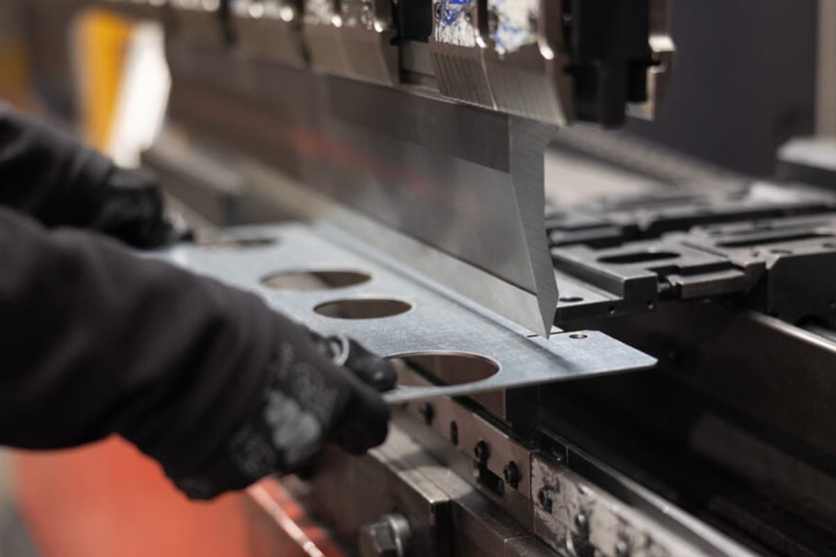
Before we learn how to use press brake effectively, let's have a dip view about the press brake machine tool. Press brake is an essential tool in metal fabrication, which is used to bend the metal sheet into the required shape, offering controllable and consistent bending force. It clamps the workpiece between a matching top tool and bottom die to bend.
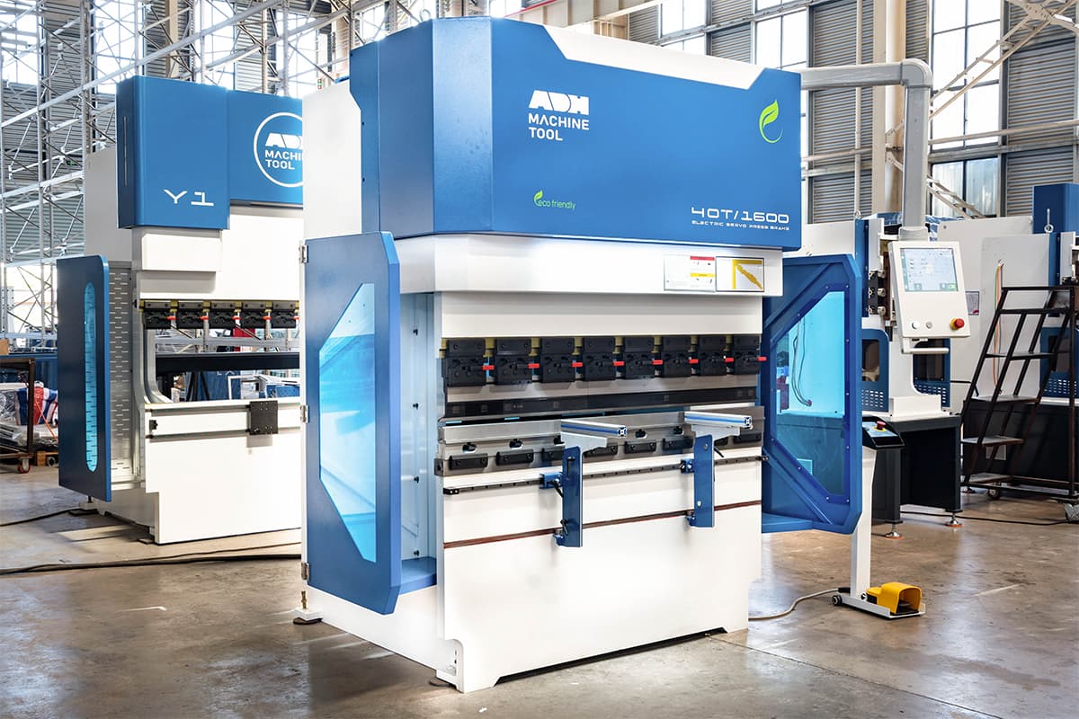
Common types of press brake machines are mechanical press brakes, hydraulic press brakes, electric press brakes, and CNC press brakes. Nowadays, modern press brakes are usually composed of a bed, ram, back gauge, control system, punch and die set, etc., which work together to form and bend sheet metal. Two C-frames, connected to a table at the bottom and a movable beam at the top, form the press brake’s sides.
Press brake bending methods usually include air bending, bottom bending, and coining process. Press brake metal forming is vital in the sheet metal fabrication industry. The difficulty of press brake forming is related to the material grade you are forming. The harder the material is, the more springback it is.
The press brake forming techniques compensate the spring back not by bottom bending, but through the proper use of press brake tooling. Choosing the appropriate tooling is critical for achieving accurate and efficient press brake operations. Here are key considerations for selecting the right tooling for your bending machine. For a deeper understanding of different tooling types and configurations, check out the Comprehensive Guide to Press Brake Tools.
II. Laying the Foundation: Essential Knowledge Before Operation
2.1 Press Brake Anatomy: A Visual Breakdown of Core Components
A modern press brake is a precise integration of mechanical, hydraulic, and electronic engineering. Understanding the function and interplay of its core components is essential for achieving accurate control. Readers seeking to compare press brakes with other forming tools can refer to the Guide to Punch Press for context on mechanical vs. hydraulic forming systems.
(1) Core Component Overview
Frame: The structural backbone of the machine, typically fabricated from high-strength steel plates in C-frame or O-frame designs. It provides stable support for all components and resists the immense stresses generated during bending. The rigidity of the frame directly impacts long-term precision and stability.
Ram: The vertically moving section that drives the punch downward. The ram’s movement accuracy, repeat positioning precision, and synchronized motion on both sides are crucial for consistent bend angles.
Bed: The stationary base used to mount the die and support the workpiece. It must remain perfectly parallel to the ram; any deviation can cause angle inconsistencies along the bend line. Many modern machines incorporate crowning systems into the bed to compensate for deflection.
Punch: Mounted on the ram, this upper tool applies bending force directly to the sheet. Its shape, angle, and tip radius determine the resulting internal bend radius and profile.
Die: Installed on the bed, its V-shaped opening supports the sheet. The width of the V-opening is a critical factor influencing required tonnage and the final bend radius. For those aiming to master die selection and bending accuracy, the Guide to Press Brake Tooling and Bending provides step-by-step insights into matching punches and dies effectively.
Backgauge: Located at the rear of the machine, this precision positioning device sets the flange length—the distance from the bend line to the sheet edge. Modern CNC backgauges can control multiple axes (X, R, Z1, Z2, etc.) to achieve accurate positioning for complex shapes.
CNC Control: The “brain” of the press brake. Operators input parameters such as material type, thickness, and target angle; the system automatically calculates required pressure, ram depth, and backgauge position, controlling the entire bending process. For operators looking to fine-tune their setup efficiency and component performance, learning from Mastering Press Brake Accessories provides actionable insights on optimizing each component.
(2) Power Mechanisms Explained
Mechanical: Utilizes a flywheel and crank linkage to drive the ram—fast and efficient, but with fixed stroke and speed. Once activated, it cannot be stopped mid-cycle, posing higher safety risks and offering less flexible pressure control. Rarely used today for high-precision applications.
Hydraulic: The current industry standard. Controls oil pressure and flow within hydraulic cylinders to move the ram. Offers powerful, flexible control with adjustable stroke, the ability to stop or reverse at any point, and precise pressure regulation—ideal for thick plates and complex parts.
To achieve optimal forming results, understanding how to calibrate system pressure is essential—learn more about How to Adjust the Press Brake Back Pressure.
Servo-Electric: Driven by high-power servo motors via pulleys or ball screws, eliminating hydraulic oil. Delivers exceptional precision, speed, low noise, and energy efficiency—using roughly 50% of the energy of hydraulic presses. Offers extremely high repeat positioning accuracy, making it perfect for precision, high-speed thin sheet work.
(3) Key Terminology Reference
Tonnage: The maximum force a press brake can apply—a core measure of its capacity. Required tonnage increases with material tensile strength, thickness, and bend length, and decreases with wider die openings.
Bending Length: The maximum width of the workpiece the machine can process.
Bend Angle: The final angle formed after bending.
Springback: The phenomenon where metal partially returns toward its original shape after bending due to elastic recovery—a universal characteristic of cold forming processes.
K-Factor: A coefficient related to material properties, thickness, and bend radius used to calculate flat patterns before bending. It represents the positional shift of the “neutral axis” (the layer neither stretched nor compressed) within the material’s thickness. Accurate K-factors are essential for meeting design specifications.
2.2 Safety Boundaries: Non-Negotiable Protocols and Environmental Standards
Operating a press brake ranks among the most hazardous tasks in a sheet metal workshop—any lapse can result in severe injury. Safety protocols are not mere suggestions; they are strict boundaries that must be observed.
(1) Personal Protective Equipment (PPE) Checklist
Operators must always wear the “triple set” of PPE:
- Safety Glasses: Protect eyes from flying metal fragments or broken tooling.
- Cut-Resistant Gloves: Safeguard hands when handling sharp sheet edges.
- Steel-Toe Safety Shoes: Prevent foot injuries from dropped heavy workpieces or tools.
(2) Built-In Machine Safety Systems
Modern press brakes feature multiple safety devices that must be verified before operation:
- Light Curtains: Create an invisible infrared barrier around the operating zone. If a hand or object enters the area while the ram is descending, the system instantly signals an emergency stop.
- Two-Hand Controls: Require simultaneous activation of two spaced-apart buttons to initiate ram movement, ensuring both hands remain safely away from the tooling area.
- Emergency Stop: Large red mushroom-head buttons located at key points on the machine. Pressing any will immediately cut all power and halt all movement.
- Golden Workspace Standards
A safe, efficient workspace is equally vital—follow the “three essentials” checklist:
1. Clean and Uncluttered: Keep floors free of oil, debris, and tools to ensure smooth movement and prevent slips or trips.
2. Well-Lit: Good lighting aids in reading drawings, aligning bend lines, and reducing operational errors.
3. Adequate Space: Allow sufficient clearance for rotating and handling large sheets to avoid collisions with people or equipment.
2.3 Blueprint and Material: The Source of a Perfect Bend
Success in bending begins the moment you interpret the blueprint and inspect the material—any error at this stage will undermine all subsequent efforts.
(1) Blueprint Reading Essentials
A sheet metal bending drawing contains all manufacturing instructions—quickly identify:
- Bend Lines: Indicate where bends occur.
- Angles and Directions: Specify each target bend angle (e.g., 90°, 135°) and whether the bend is up or down.
- Dimensions and Tolerances: Include flange lengths, distances from holes to bend lines, and acceptable error margins.
- Material Specifications: Clearly state the material type (e.g., SUS304, AL5052) and thickness.
- Material Verification Checklist
Upon receiving the sheet material, always verify:
- Verify material type, thickness, and hardness: Use a caliper to measure thickness and confirm it matches the specifications on the drawing. Different materials and hardness levels require distinct bending parameters.
- Pay close attention to grain direction: During rolling, sheet metal develops a grain structure. Bending along the grain significantly increases the risk of cracking—especially when the bend radius is small. The optimal bending direction is perpendicular to the grain. If bending along the grain is unavoidable, increase the bend radius accordingly.
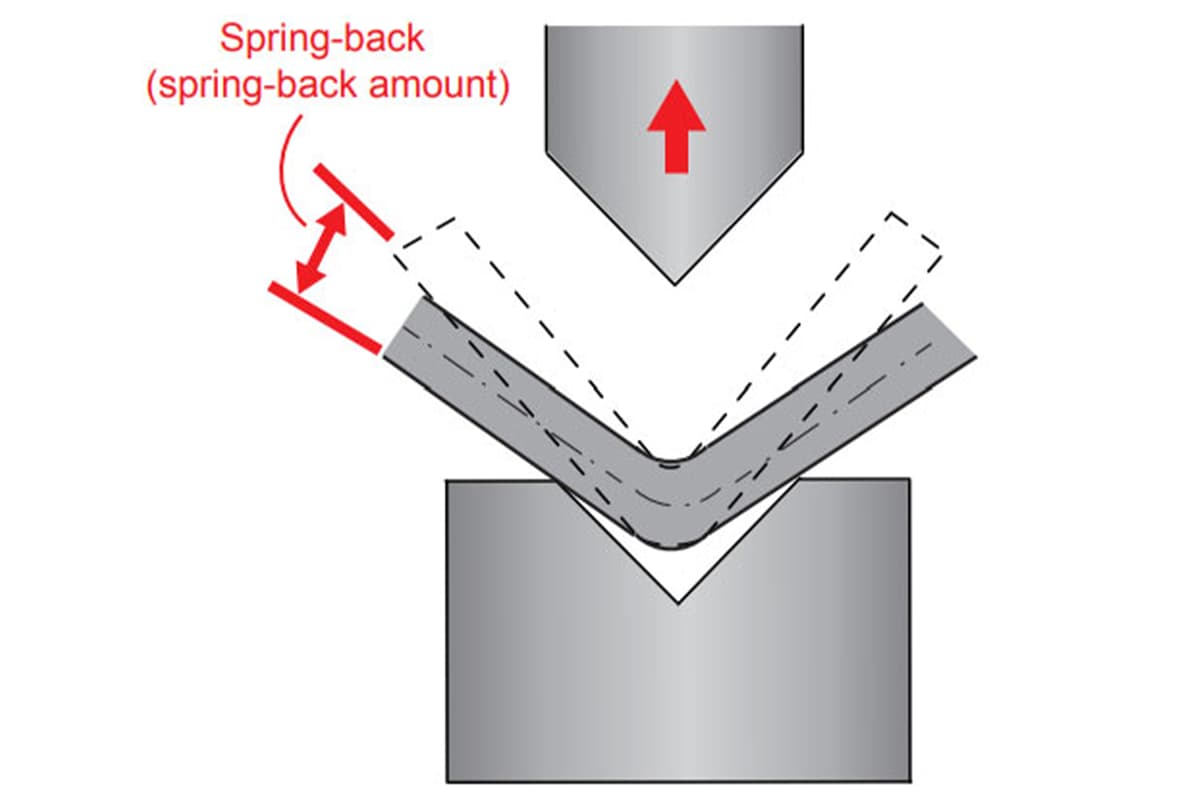
Why does a 90° setting rarely produce a perfect 90° bend? The culprit is the metal’s tendency to elastically recover after bending.
When the punch applies force to the sheet, the material undergoes both plastic deformation (permanent) and elastic deformation (recoverable). Once the punch is removed, the force disappears, and the suppressed elastic deformation is released—causing the angle to “spring back” slightly.
Springback is not a fixed value—it is influenced by multiple factors:
- Material strength: The higher the yield strength (e.g., high-strength steel), the greater the springback.
- Material thickness: Thicker sheets tend to exhibit less springback.
- Bend radius: A larger bend radius relative to sheet thickness results in greater springback.
- Bending method: For example, air bending produces more springback than bottoming.

To counteract springback, skilled operators or advanced CNC systems use overbending—programming a slightly smaller angle (e.g., 88°) so that after springback it settles at the desired 90°. Modern high-end press brakes may even feature laser angle measurement systems that monitor the bend in real time and dynamically adjust the punch depth, virtually eliminating springback uncertainty.
Ⅲ. Selecting the Right Tooling
3.1 Tool Material and Hardness
- Tool Material: The material of the tooling significantly impacts its performance and durability. Common materials include hardened steel, carbide, and specialized alloys. Hardened steel tools are durable and resistant to wear, making them suitable for heavy-duty applications. Carbide tools offer high hardness and wear resistance, ideal for precise and repeated operations. For example, using hardened steel tools for bending thick stainless steel sheets can prevent premature wear.
- Tool Hardness: Ensure the tooling has adequate hardness to withstand the forces involved in sheet metal bending. Higher hardness levels provide better wear resistance but may be more brittle. A tool with a Rockwell hardness of 60 HRC is typically suitable for bending high-strength materials.
3.2 Tool Coatings
- Coatings: Tool coatings, such as titanium nitride (TiN) or diamond-like carbon (DLC), can enhance wear resistance and reduce friction, extending the tool's lifespan. TiN-coated tools, for instance, can last up to three times longer than uncoated tools in high-volume production environments.
3.3 Workpiece Material and Thickness
- Material Type: Different materials have varying properties that affect the bending process. For instance, aluminum is more malleable than steel, requiring different tooling considerations. Stainless steel, with its higher tensile strength, may require harder and more robust tooling.
- Thickness: The thickness of the workpiece determines the tonnage required and the type of tooling. Thicker materials need more robust tooling to withstand the higher forces without deforming or breaking. For example, bending a 10mm thick steel plate requires a tool capable of handling higher tonnage compared to bending a 2mm aluminum sheet.
3.4 Tooling Types and Configurations
Punches and Dies: These are the primary tools in every press brake operation. The punch is the top tool that presses the material into the die, the lower tool that shapes the bend.
- V-Dies: Commonly used for air bending, V-dies come in various sizes to match different material thicknesses and bend angles.
- Gooseneck Punches: Designed for forming deep bends without interference from the punch body.
- Acute Angle Punches and Dies: Used for making sharp bends and angles less than 90 degrees.
- Specialty Tooling: For specific applications such as hemming, offset bends, or box bending, specialty tooling can be used. Hemming tools are used to fold the edge of the sheet metal back onto itself, while offset tools create a Z-shaped bend.
3.5 Compatibility and Machine Capacity
- Tooling Compatibility: Ensure the tooling is compatible with your press brake model. Check the tool clamping system, tool length, and mounting style. Some press brakes use standardized tooling systems like European, American, or Wila, which may influence your selection.
- Machine Capacity: Match the tooling to the capacity of your press brake. Consider the maximum tonnage, stroke length, and bed width. Using tooling that exceeds the machine's capacity can lead to damage and safety hazards.
3.6 Precision and Repeatability
- Tolerance Requirements: For high-precision applications, choose tooling that offers tight tolerances and minimal deflection. Precision-ground tools provide better accuracy and repeatability.
- Backgauge Integration: High-quality tooling should integrate well with the press brake's backgauge system to ensure consistent positioning and accurate bends.
3.7 Safety Considerations
- Tool Maintenance: Regular inspection and maintenance of tooling are essential for safe operation. Look for signs of wear such as cracks or deformations and replace tools as needed. For example, inspect the tooling for any chips or burrs that could affect the quality of the bends.
- Safety Features: Some tooling includes safety features like anti-slip surfaces or protective coatings to reduce the risk of accidents.
3.8 Cost-Effectiveness and Longevity
- Initial Investment vs. Long-Term Benefits: While higher-quality tooling may come with a higher initial cost, it often provides better performance, longer lifespan, and reduced downtime, leading to overall cost savings.
- Tooling Longevity: Invest in tooling that offers a good balance between durability and cost. Consider the frequency of use and the types of materials being processed.
3.9 User Experience and Skill Level
- Ease of Use: Choose tooling that is user-friendly and easy to set up, especially if multiple operators will be using the press brake.
- Operator Training: Ensure that operators are trained on the proper use and maintenance of the tooling to maximize efficiency and safety.
Ⅳ. How to Operate A Press Brake
4.1 Pre-Operation Checks
Review the Manual
- Thoroughly read the press brake's operation manual to understand the machine's capabilities, limitations, and safety features.
- Familiarize yourself with the control panel and any specific instructions related to the model you are using.
Inspect the Machine
- Conduct a visual inspection to check for any visible signs of wear, damage, or leaks.
- Verify that all safety guards are in place and functioning correctly.
- Ensure the emergency stop buttons are operational.
Check Tooling
- Inspect the punch and die for any signs of wear or damage.
- Verify that the tooling is properly aligned and securely fastened.
- Ensure the tooling matches the requirements of the material and bend you plan to perform.
Workspace Organization Requirements
- Clutter-Free Environment: Ensure that all tools, materials, and equipment are stored properly, keeping walkways clear of obstructions that could cause tripping hazards.
- Lubrication Management: Avoid over-lubrication of moving parts as this can lead to contamination or insufficient friction in critical areas like ball screws or guide rails.
4.2 Setting Up the Press Brake
Proper setup of the press brake is critical to achieving accurate bends and ensuring the safety of operations. The following steps outline the setup process:
(1) Select Appropriate Tooling:
Choose the correct matching punch and die based on the material type and the desired bend angle.
Ensure the tooling is in good condition and free from damage.
(2) Install and Align Tooling:
Carefully attach the punch to the ram and the die to the bed, ensuring they are securely fastened.
Use alignment tools or methods to ensure the punch and die are properly aligned. Misalignment can lead to inaccurate bends and potential damage.
(3) Program the Back Gauge:
Set the back gauge to the required positions based on the bending sequence and dimensions of the workpiece.
For CNC press brakes, input the necessary parameters into the control system for automatic positioning.
(4) Adjust Ram Stroke:
Set the ram stroke to the appropriate depth for the material thickness and the desired bend. This prevents over-bending or damaging the material.
4.3 Performing the Bending Operation
With the setup complete, you can proceed with the bending operation. Following these steps makes bending precise and safe:
(1) Position the Workpiece:
Place the metal plate on the bed, ensuring it is properly aligned with the backgauge.
Use clamps or other holding devices if necessary to keep the workpiece in position.
Verify the dimensions and alignment of the workpiece to ensure accuracy before starting the bending process.
(2) Initiate the Bend:
Activate the press brake using the control panel or foot pedal, depending on the machine’s design.
Monitor the initial bending process to ensure the workpiece is bending correctly.
(3) Monitor the Process:
Keep a close watch on the bending process to ensure it is proceeding as expected.
Listen for unusual noises and watch for unexpected movements, which could indicate a problem. Adjust the settings as necessary to correct any deviations.
(4) Check Bend Accuracy:
After completing a bend, carefully remove the workpiece from the machine, and measure the angle and dimensions of the bend to ensure it meets specifications.
Adjust the back gauge, ram stroke, or tooling as necessary to correct any inaccuracies.
(5) Sequence of Bends:
If the part requires multiple bends, follow the predetermined sequence to ensure accuracy and avoid reworking.
4.4 Final Inspection and Quality Control
Once the bending operation is complete, performing a thorough inspection ensures the quality and consistency of the finished part:
(1) Power Down the Machine
Turn off the press brake and follow the manufacturer’s shutdown procedures.
Ensure all moving parts have come to a complete stop before performing any further actions.
(2) Dimensional Checks:
Use calipers, die angle finders, and other precision tools to verify the final dimensions of the bends.
Compare the measurements against the design specifications.
(3) Visual Inspection:
Look for any defects such as cracks, wrinkles, or surface imperfections that might affect the part's integrity.
Ensure the bends are smooth and consistent across the workpiece.
(4) Adjustments and Corrections:
If any discrepancies or defects are found, make the necessary adjustments to the setup or process and rerun the operation on a new workpiece.
Document any changes to improve future setups and reduce errors.
(5) Clean the Work Area
Remove any debris, scrap material, or tools from the work area.
Ensure the press brake and surrounding area are clean and ready for the next operation.
(6) Perform Routine Maintenance
Conduct any necessary maintenance tasks such as lubrication, checking hydraulic fluid levels, and inspecting electrical connections.
Record maintenance activities in a log for future reference.
V. Advanced Press Brake Techniques in Practice
5.1 Advanced Press Brake Techniques
The following three techniques are the true litmus test of an operator’s skill level, playing a vital role in a product’s functionality, safety, and visual appeal.
(1) Hemming: Creating Safe, Attractive Folded Edges
Hemming involves folding the edge of a sheet completely back onto itself to produce a smooth, thickened safety edge. It is widely used to increase part rigidity, eliminate sharp edges, or prepare components for subsequent assembly. A standard hemming process is achieved through a precise two-step method:
1. Step One: Acute Bend Using an acute-angle punch (typically 30°) and a matching die, the sheet edge is first bent to a sharp angle well below 90°. This pre-bend shapes the fold in advance, preventing uncontrolled deformation or cracking during the final flattening.
2. Step Two: Flattening The pre-bent workpiece is transferred to a flattening die. A flat punch then applies pressure significantly greater than for standard bends to completely flatten and close the fold. This requires substantial tonnage, as the material is being forced into intense plastic deformation.

Expert Tip: Modern press brakes often feature spring-loaded two-stage hemming dies that cleverly integrate the acute V-groove and flattening surface into the same lower die. This allows both operations to be completed in a single stroke, delivering exponential gains in efficiency.
(2) Offset Bends: One Setup for a Z-Shaped Step
Offset bending (also known as Z-bending) creates two parallel bends in opposite directions on a single workpiece, producing a stepped or Z-shaped profile. This form is commonly used for overlapping parts, clearance, or added structural strength.
Methods:
Specialized Tooling (Most Efficient): Using dedicated joggle die sets, whose punches and dies already have a Z-shaped profile, both bends can be formed in a single stroke. This delivers maximum efficiency, consistency, and precision.
Two-Step with Standard Tooling (Most Versatile): Without specialized tooling, the offset can be made in two consecutive bends. First, perform a 90° bend at the target position; then flip the workpiece 180° and make a second 90° bend in the opposite direction. The distance between the two bends determines the offset height. The key challenge is ensuring precise positioning and parallelism for the second bend.
(3) Large Radius Bending: Step Bending for Smooth Curves
When the desired bend radius is much larger than the sheet thickness (for example, eight times the thickness or more), using a standard large-R die becomes impractical or prohibitively expensive. In such cases, step bending—also called bump bending—is an ingenious, highly adaptable technique. The principle is to approximate a large smooth curve using a sequence of closely spaced, small-angle bends.
- Programming Essentials: The operator simply inputs the target arc’s radius, angle, and arc length into the CNC system.
- System Calculation: Advanced CNC systems automatically break the large arc into dozens or even hundreds of tiny straight segments. They calculate the pitch—the distance the back gauge advances each time—and the step angle for each small bend.
- Execution: The operator positions the sheet against the back gauge and starts the machine. The back gauge advances in small, continuous steps while the ram performs shallow bends in sync, gradually “bumping” the material into the required large radius. The smaller the pitch and the greater the number of steps, the smoother and more perfect the resulting curve.
5.2 Efficiency Enhancement Strategies
In modern manufacturing, the adage “time is money” holds true more than ever. The following strategies are designed to drastically reduce non-productive time, enabling the press brake to deliver maximum value.
(1) A Revolution in Tool Change: From Hours to Minutes Traditionally, changing press brake tooling was a time-consuming, labor-intensive, and hazardous task, often taking 30 minutes to several hours. This extended downtime was a major bottleneck for small-batch, high-mix production. The advent of Quick Die Change (QDC) systems completely transformed this scenario, slashing tool change time to mere minutes or even seconds—a true leap in efficiency.
(2) Core Technologies:
Hydraulic/Pneumatic Clamping: Replaces the traditional manual tightening of bolts. With the push of a button, clamps along the upper beam and worktable instantly lock or release all tooling.
Segmented & Self-Aligning Tooling: Standard-length short dies can be quickly combined to any required length, and precision engineering ensures they automatically align to the centerline when clamped—no manual fine-tuning needed.
(3) Major Benefits:
Drastic Downtime Reduction: The machine spends over 95% of its time producing instead of waiting.
Small-Batch Viability: Even orders of just a few pieces can be profitable thanks to minimal changeover time.
Significantly Improved Safety: Automated operation reduces the risks associated with manually handling heavy tooling.
Batch Production Optimization: The Art of Bend Sequencing For complex parts with multiple bends, the sequence directly affects both efficiency and feasibility. A poor order can cause the workpiece to collide or interfere with the press brake or tooling during later bends, or require excessive flipping and rotating by the operator. Optimization Goal: Find a “golden path” that minimizes tooling changes and workpiece flips while completely avoiding collisions.
Manual Planning: Experienced operators mentally rehearse the entire process like a chess game, often following basic principles such as “short edges first, then long edges” or “bend the middle first, then the sides.”
Automated Software Optimization: This is where modern offline programming software truly shines. After importing the part’s 3D model, the software can simulate all possible bend sequences within seconds and, using collision detection algorithms, automatically recommend the most efficient, interference-free production path.
The Value of Offline Programming: Achieving Zero Downtime When Switching Tasks Offline Programming shifts the creation, simulation, and optimization of bending programs from the costly machine control panel to a standard office computer. Traditional approach: An operator stands at the machine, thinking through each step while inputting parameters, running trial bends, and making adjustments. During this entire process, equipment worth hundreds of thousands or even millions sits idle. Offline programming approach:
Parallel Workflow: While one press brake is busy completing Task A, the engineer is already preparing and virtually simulating all programs for Tasks B, C, and D on the computer.
Seamless Transition: As soon as Task A finishes, the fully tested program and setup drawings for Task B are instantly transmitted to the machine via the network. The operator simply installs the tooling according to the drawings—especially fast if using QDC—and can start production immediately.
(4) Key Advantages:
- Maximized Equipment Utilization: Keep the press brake focused on its core function—bending—rather than programming.
- Proactive Problem-Solving: High-precision simulations allow potential collision issues to be identified and resolved in the virtual environment, ensuring a first-run success and eliminating scrap or rework.
- Knowledge Preservation: Proven manufacturing solutions are stored as digital files, becoming valuable corporate assets that no longer depend on an individual operator’s intuition or memory. To see which modern press brakes incorporate these advanced features, feel free to explore our product Brochures.
Ⅵ. Safety Precautions in Using Press Brakes
6.1 General Safety Measures
Personal Protective Equipment (PPE):
Operators need to know to wear appropriate PPE at all times. This includes safety glasses to protect the eyes from metal shards, gloves to shield hands from cuts and abrasions, and steel-toed boots to protect feet from heavy objects. Additionally, hearing protection is recommended due to the noise generated during operation.
Safe Working Environment:
Maintaining a clean and organized workspace is crucial. Floors should be free of obstacles and spills to prevent slips and falls. Proper lighting ensures that operators can see their work clearly, reducing the risk of errors and accidents. It's also essential to have clear emergency exits and accessible fire extinguishers in the vicinity.
6.2 Machine-Specific Safety
Pre-operation Checks:
Before using the press brake, operators should know to perform a series of pre-operation checks. This includes verifying that all safety guards and barriers are in place and functioning correctly.
Inspecting the machine for any signs of damage or wear, such as cracks or leaks, is also necessary to prevent malfunctions during operation. Additionally, operators should ensure that the workpiece is securely clamped and that the tooling is appropriate for the task.
Emergency Stop Procedures:
Understanding and being able to quickly access the emergency stop mechanism is critical. Operators should familiarize themselves with the location and operation of the emergency stop button or pedal.
In the event of an emergency, knowing how to halt the machine immediately can prevent injuries and further damage to the equipment.
Ⅶ. Maintenance and Troubleshooting
7.1 Regular Maintenance
Daily Check-Up Routines
- Visual Inspection: Conduct a thorough visual inspection of the machine, looking for any signs of wear, damage, or leaks.
- Safety Guards and Sensors: Ensure all safety guards and sensors are in place and functioning correctly.
- Hydraulic Fluid Levels: Check the hydraulic fluid levels and top up if necessary, ensuring there are no leaks or contamination.
- Clean the Machine: Remove any metal shavings, dust, and debris that may have accumulated on the machine and work area.
- Lubricate Moving Parts: Lubricate all moving parts, such as the ram guides, back gauge screw, and any other critical points per the manufacturer’s guidelines.
- Check Bolts and Fasteners: Ensure that all bolts and fasteners are tightened properly to avoid any loose components during operation.
Lubrication and Cleaning Procedures
- Lubrication Schedule: Follow the manufacturer's recommended lubrication schedule, using the specified lubricants to ensure compatibility and effectiveness.
- Cleaning Tools and Solvents: Use appropriate cleaning tools and solvents to remove grime, grease, and debris without damaging the machine parts.
- Focus Areas: Pay special attention to high-usage areas such as the ram guides, back gauge slides, and punch and die holders. These areas experience more friction and require regular attention.
- Preventive Measures: Implement preventive maintenance measures such as regularly scheduled deep cleaning and scheduled replacement of consumable parts like filters and seals.
7.2 Common Issues and Solutions
Addressing Material Springback
Issue: Material springback occurs when the bending plate tries to return to its original shape after bending, resulting in less precise angles.
Solution:
- Over-Bending: Adjust the bend angle slightly beyond the desired angle to compensate for springback.
- Material Analysis: Understand the material properties and select appropriate tooling to minimize springback.
- Trial and Error: Perform test bends on scrap pieces to determine the correct over-bend angle for that specific batch of material.
Hydraulic System Issues
Issue: Hydraulic problems, such as inconsistent pressure or fluid leaks, can affect the machine's performance.
Solution:
- Monitor Pressure: Regularly check and monitor hydraulic pressure levels to ensure they are within the specified range.
- Inspect Connections: Ensure all hydraulic connections are secure and not leaking.
- Fluid Replacement: Change hydraulic fluids as recommended by the manufacturer to maintain the system's integrity.
Control System Failures
Issue: Malfunctions in the control system, particularly in CNC press brakes, can lead to operational disruptions.
Solution:
- Software Updates: Keep the control software up-to-date to benefit from the latest improvements and bug fixes.
- Diagnostic Tools: Utilize built-in diagnostic tools to identify and troubleshoot software issues.
- Professional Support: Seek assistance from qualified technicians for complex control system problems, ensuring the machine's programming is error-free.
Alignment Problems
Issue: Misalignment of the punch and die can lead to inaccurate bends and potential damage to the workpiece.
Solution:
- Check Alignment: Routinely check the alignment of the punch and die, especially after tooling changes or machine maintenance.
- Use Precision Alignment Tools: Employ precision tools to ensure accurate alignment for consistent bending results.
Ⅷ. FAQs
1. What are the different types of bends you can achieve with a press brake?
Press brakes can achieve various types of bends, including:
- Air Bending: The most common method, where the punch presses the material into an open die, forming an angle.
- Bottom Bending: The material is pressed into the bottom of the die, producing more precise bends. In bottoming, the punch tip radius determines the inside bend radius, and the die angle determines your bend angle.
- Coining: Involves pressing the punch into the die with significant force, creating highly precise bends and minimal springback.
2. How can you minimize errors while using a press brake?
To minimize errors during press brake operations:
- Ensure Proper Setup: Double-check the alignment of the punch and die, back gauge positions, and ram stroke settings.
- Use Consistent Parameters: Maintain uniform setup parameters for each batch of work.
- Conduct Test Bends: Perform test bends on scrap material to verify settings before bending the actual workpieces.
- Monitor Material Properties: Different materials may respond differently to bending forces, so adjust settings accordingly.
- Maintain Equipment: Regular maintenance and timely replacement of worn components help in maintaining accurate operations.
3. How do you troubleshoot a press brake if it’s not working properly?
When troubleshooting a press brake:
- Check the Basics: Ensure the machine is plugged in, powered on, and emergency stops are disengaged.
- Inspect Safety Systems: Verify that all safety guards and sensors are functioning.
- Hydraulic System: Check fluid levels, look for leaks, and ensure pressure is within the specified range.
- Control Systems: Use diagnostic tools to check for software or hardware issues in CNC systems.
- Mechanical Components: Inspect moving parts for wear or damage and replace any defective components.