I. Introduction
As an essential piece of equipment, the press brake plays a pivotal role in metal sheet fabrication. It is mainly designed for achieving metal sheet precise bending and forming. It is widely used in various precision machinery industries such as automobile manufacturing, aerospace, electrical appliance manufacturing, etc., which can ensure the products’ precision and production efficiency.
However, there is always a problem that the press brake won’t go up, troubling many sheet metal enterprises. This bending problem may not only cause production stagnation and delivery delays but also directly affect the quality of the workpiece, increasing unnecessary repair costs and production losses.
Our passage aims to offer a comprehensive solving guide for this troublesome issue. We will delve into the various reasons why the press brake won’t go up, and combine the abundant sheet metal knowledge ranging from equipment maintenance, and operation regulations to malfunction troubleshooting, to talk about how to solve this problem, making the operation stable and efficient and the overall the procedure smooth and effective.
For related cases and safety guidelines in similar machinery, you may also refer to Shearing Machine Troubleshooting & Safety to expand your technical knowledge and ensure comprehensive workshop safety.
II. Understanding Press Brakes
2.1 Basic Components of Press Brake Machine
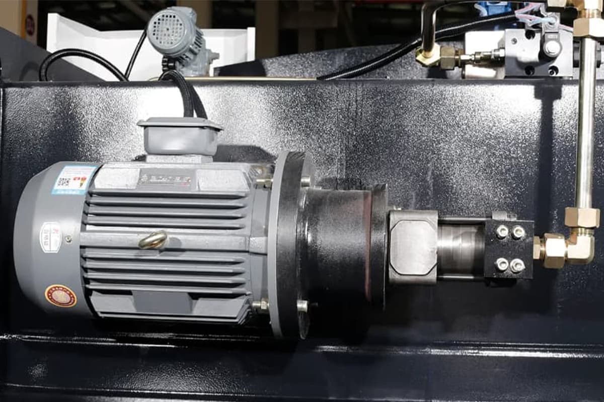
Press brake is mainly composed of the following basic components: body frame, hydraulic system, electric control system, back gauge device, tooling (upper punch and bottom die), and worktable.
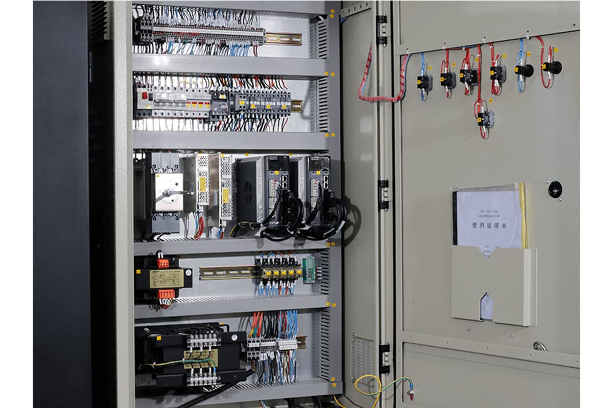
The body frame is the basic structure of the equipment, the hydraulic system is responsible for the pressure required by bending, electricity control system can ensure the precision and automation degree of the equipment operation.
The back gauge is designed for positioning the sheet, and the tooling determines the shape and size of the workpiece, while the workbench is designed for supporting and fixing the sheet to be processed.

2.2 How Press Brakes Function in Metal Fabrication
In metal fabrication processing, the press brake plays an important role, which is assisted by strong hydraulic pressure, and can precisely bend the flat metal sheet into the required 2D or 3D shapes through adjusting the angle and distance between the upper and bottom die, achieving the high efficient forming processing of the components.
This process is of decisive significance for manufacturing various sheet metals, like boxes, shells, and brackets.
2.3 Significance of Press Brake Maintenance
The stability and lifespan of the bending machine are mainly determined by routine maintenance.
Work like regular lubrication, cleaning, checking, and replacing abrasive components can effectively avoid malfunction situations occurrence won’t go up because of aging, abrasiveness, blocking, etc.
Besides, good habits of maintenance can ensure press brake precision, lower production errors, improve production quality, prolong the equipment lifespan, and reduce downtime and maintenance costs, which is beneficial for enterprises’ consistent and highly efficient production.
Ⅲ. Systematic Troubleshooting: A Multi-Dimensional Diagnostic Funnel
Once the “golden 60 seconds” of emergency handling and preliminary assessment are over, avoid jumping blindly into disassembly. True experts know to activate a structured “diagnostic funnel”—a step-by-step analytical framework that moves from surface symptoms to underlying causes. This model systematically cross-verifies the hydraulic, electrical, and mechanical systems to pinpoint issues with precision. It’s not just a method—it’s a mindset.
3.1 Deep Dive into the Hydraulic System: Following the Flow, Tracing Pressure and Movement
The hydraulic system is the “heart and circulatory network” of a press brake, with over 70% of ‘failure to rise’ issues originating here. The diagnostic route must follow the transmission path of hydraulic energy—from the “fluid condition,” the system’s vital sign, to the “valve assembly,” its command center, and finally to the “power source,” its driving force.

3.1.1 First Layer: Oil Condition (Quality, Level, Temperature)
The hydraulic fluid is the system’s “blood,” and its condition is the starting point of any diagnosis—an easily overlooked indicator of system health.
- Is the oil level within the standard range?
- Check: Inspect the tank’s level gauge to ensure the fluid level lies between the minimum (L) and maximum (H) marks.
- Insight: The danger of low oil level goes far beyond simple shortage—it can cause the pump to draw in air. Compressed air within a hydraulic system leads to the deadly phenomenon of cavitation, noticeable by a high-pitched hiss or a rattling noise similar to a damaged bearing. Cavitation produces unstable pressure, erratic ram movement, and localized high-temperature, high-pressure spots that erode metal surfaces like micro-explosions, resulting in irreversible pump damage.
- Is the fluid cloudy, milky, or showing metallic particles?
- Check: Take a small sample in a clean container and observe under light. Cloudiness indicates solid contamination; a milky appearance means water contamination and emulsification.
- Insight: Tiny metal particles signal severe internal wear (pump, valve spool, or cylinder). Water contamination is equally destructive—it degrades lubrication, accelerates oxidation, and reacts with additives to form acids that corrode valve spools, causing sluggish or completely stuck operation.
- Is the oil overheated?
- Check: Read the thermometer or use an infrared sensor on the tank’s outer wall. The normal working range is 35–55°C; exceeding 60°C is abnormal.
- Insight: Continuous overheating signals internal energy loss, typically pointing to three issues:
(1) prolonged overflow from a relief valve stuck open or pressure set too high, converting pump power into heat;
(2) severe internal leakage from worn pumps, cylinders, or valves allowing high-pressure oil to bypass;
(3) cooling system failure—blocked heat exchangers or inoperative fans.
3.1.2 Second Layer: Valve Assemblies and Solenoids (Command Executors)
When the system fluid is healthy, the issue may lie with the valves that distribute it.
- Listen for a distinct “click” from the solenoid valve when the lift command is triggered
- Check: In a quiet setting, press the lift button and listen directly or use a metal screwdriver as a makeshift stethoscope—touch its tip to the solenoid and the handle to your ear—to detect the engagement click.
- Insight: No sound suggests an electrical fault (coil unpowered or burned). Sound but no motion indicates a hydraulic issue—possibly a valve spool stuck by sludge or contamination, or in complex cartridge valves, a blocked pilot circuit preventing the main spool from opening.
- Use a multimeter to verify voltage at the solenoid coil
- Check: After ensuring power-off safety and understanding the circuit, unplug the solenoid connector and measure if the proper voltage (e.g., 24V DC or 220V AC) appears when the lift command is given.
- Insight: Voltage present but valve inactive means the fault is internal to the solenoid (burned coil or jammed spool). No voltage indicates the problem lies upstream in electrical control—PLC output, relay, or wiring.
- Check for sticking in relief or directional valve spools (try manual override)
- Check: Many solenoid valves feature a manual override, a tiny recessed button or pin. With power safely off, gently press it using a narrow tool to simulate solenoid actuation. If movement occurs, the spool is fine and the fault lies in the electrical control; if not, the spool is stuck or the downstream passage is obstructed.
- Deep Insight (a hidden trap): Excessive back pressure due to return flow restriction. When the slider rises, oil from the upper cylinder chamber must return freely to the tank. If a hydraulic check valve or balancing valve fails to open, or the return filter is clogged, massive back pressure builds up in the upper chamber—acting like an invisible air cushion resisting the upward thrust. This is a subtle yet often overlooked killer fault.

3.1.3 Third Layer: Power Source (Pump and Piping)
If commands are correctly issued and components are ready, it’s time to examine the system’s core source of power—the pump.
- Is pump pressure stable? Any unusual sound or strong vibration?
- Check: Observe the system’s pressure gauge. When the pump starts (without performing any motion), standby pressure should stabilize. Upon issuing the lift command, pressure must rise swiftly.
- Insight: If pressure remains at zero or fails to build, common causes include a broken coupling between motor and pump (motor idling), severe pump wear causing internal leakage, or a relief valve stuck open, allowing all pressure to bypass directly to the tank.
- Inspect suction and return filters for clogging
- Check: Review filter clog indicators (if available) or remove filters for direct inspection.
- Insight: A blocked suction filter mimics low oil level issues, causing air intake and pump cavitation. A clogged return filter leads to both excessive back pressure and ineffective filtration—allowing contaminants to circulate and worsen system wear.
- Check high-pressure hose for internal layer separation or blockage
- Inspection: Although rare, this fault can be extremely serious. Over time, the inner rubber lining of low-quality oil hoses may deteriorate and detach, forming a one-way “flap valve” that blocks oil flow in a specific direction. You can test this by disconnecting both ends of the hose and blowing low-pressure compressed air through it to check for obstructions.
3.2 Electrical Control Circuit: Tracing the Path of a Lost Signal
The electrical system functions as the machine’s “nervous network.” Any break in the signal chain—from transmission to reception—will effectively leave the entire system “disconnected.”
3.2.1 Input Signal Verification
- Test the continuity of the UP button and foot switch: Use a multimeter in continuity or resistance mode to measure state changes when the switch is pressed and released. The foot switch cable, often subjected to dragging and pressure, is a common failure point.
- Check interlock signals from the safety light curtain and safety doors: Modern press brakes have rigorous safety logic. Verify on the control panel whether there are any safety circuit alarms. Ensure the light curtain is free from oil, dust, or debris, and confirm the rear safety doors are fully closed and have properly engaged their sensors.
3.2.2 Logic Flow Diagnosis
- Inspect relays and contactors controlling the UP motion for pitting or sticking contacts: This is a common failure point on older machines. Transparent relay covers allow visual observation of contact movement. Pitted or welded contacts cause poor conductivity, interrupting signal output.
- Check the PLC/CNC controller’s output indicators to confirm if the UP signal is being sent: This is the most straightforward test. Each output point (Y point) on the PLC control cabinet has an LED indicator. If the UP command is issued and the corresponding Y-point LED (controlling the solenoid valve) lights up but the solenoid fails to energize, the fault is definitely within the wiring between the PLC output and the solenoid valve—such as a loose terminal or broken cable.

3.2.3 Output and Feedback Detection
- Inspect limit switches and sensor conditions
- Check the upper and lower limit switches and position sensors for sticking, contamination, or physical damage.
- Clean sensor surfaces to ensure stable signal transmission and verify that no connectors are loose or misaligned.
- Understand the control logic deeply The core logic of a CNC press brake requires the system to confirm, through position sensors (such as a linear scale), that the slide has completed its stroke—e.g., reached bottom dead center (BDC)—before executing the next command (such as the UP movement). If the bottom dead center sensor signal is not properly detected due to damage, contamination, or misalignment, the controller interprets the motion as incomplete and blocks further actions to prevent program confusion. This interruption in logic can result in a “logical freeze.”
- Verify wiring and connection integrity
- Focus on the connections at motor junction boxes, solenoid connectors, and sensor plugs.
- Confirm that all connectors are tight, corrosion-free, and that wire insulation is intact.
- Note that long-term mechanical vibration can lead to intermittent contact failures—apply anti-vibration measures and schedule regular inspections.
3.3 Mechanical Structure Check: Eliminating Physical Blockages
Although less frequent, mechanical jamming can be the hardest issue to resolve once it occurs, and should therefore be ruled out early.
- Mold and workpiece inspection: Has the upper die become wedged or “bitten” into the V-groove of the lower die due to overload, uneven loading, or excessive material spring-back? This issue typically appears after the final bending operation.
- Guideways and balancing system
- Inspection: Check whether both guideway surfaces (GIBs) on the slide are properly lubricated. Use a flashlight to look carefully for scoring or galling marks.
- In-depth insight: Improper guideway clearance adjustment is a subtle cause of mechanical seizure. If the gap is too tight, thermal expansion or poor lubrication increases friction, leading to jamming; if too loose, the slide may tilt under load, also causing unilateral binding. The synchronization system is just as critical: in torsion-bar synchronized press brakes, a loose mechanical stop on one side can trigger this issue; in electro-hydraulic models, if the readings from the two linear scales exceed the controller’s allowable tolerance, the system activates “out-of-tolerance protection”, halting all motion to prevent slide tilting and potential damage to dies and components. Such protective stops are often misdiagnosed as hydraulic or electrical failures.
- Peripheral interference: Inspect rear stoppers, front supports, and other accessories to ensure none are physically contacting the slide or workpiece. Even a seemingly unrelated part can be the final obstacle preventing upward movement.
Through this systematic diagnostic funnel, you can transform a vague “machine won’t move” problem into a set of specific, testable checkpoints. You’re no longer battling the machine—you’re unraveling a logical puzzle. Each eliminated cause brings you one step closer to the truth.
Ⅳ. Practical Repair Solutions: Targeted Fixes to Revive Your Machine
The end of diagnostic analysis marks the beginning of hands-on repair. After accurately identifying the root cause through the “three-dimensional diagnostic funnel,” we now enter the critical phase—problem-solving. This chapter discards abstract theory and provides precise, field-proven repair techniques for hydraulic, electrical, and mechanical systems. Every procedure here encapsulates the hard-earned expertise of senior engineers to ensure your maintenance work is efficient, precise, and above all, safe.
4.1 Rapid Hydraulic Troubleshooting Techniques
Over 70% of “no upward movement” faults stem from the hydraulic system, typically caused by either blockage or leakage. The goal is to restore perfect flow and stable pressure transmission.
Practical Guide: Safely Cleaning and Resetting a Stuck Solenoid Valve Spool
Solenoid valve spools can jam due to sludge or microscopic debris, making them the most common culprits behind a stopped slide. Before cleaning, always internalize the safety procedures.
- Safety Preparation: Strictly follow the Lockout/Tagout (LOTO) protocol. Turn off and lock the main power switch. Release system pressure manually or wait for automatic depressurization, and confirm with a pressure gauge that hydraulic pressure is zero. Place a clean drain tray beneath the valve body.
- Remove the coil and valve body: Unscrew the retaining nut and gently remove the solenoid coil (take care to preserve the waterproof O-ring and remember its orientation). Then, evenly loosen the bolts securing the valve body and carefully lift it from the manifold block. Expect a small amount of residual hydraulic oil to flow out.
- Extract the spool: Use a non-metallic tool—such as a clean bamboo stick or rigid plastic rod—to gently and steadily push the spool out from one end of the valve body. Never use metal tools like screwdrivers or nails, as these can permanently score the spool or valve bore, causing internal leaks. Take note of any return springs at either end to prevent them from springing loose or being lost.
- Cleaning and inspection:
- Cleaning: Wipe the components using lint-free industrial wipes (such as cleanroom cloth) and fresh hydraulic oil of the same brand and grade. Never use cotton rags, ordinary tissues, or any material that sheds fibers, as these can cause secondary contamination.
- Inspection: Under bright lighting, carefully examine the valve spool surface for dark scratches, metallic burrs, or bluish discoloration—signs of localized overheating. Also, check whether the inner wall of the valve bore is smooth and mirror-like. Any visible physical damage indicates that the entire valve body must be replaced, as cleaning alone will not restore proper function.
- Reassembly and Testing: Apply a thin, even layer of fresh hydraulic oil to the cleaned valve spool, then reinstall it into the valve body exactly as it was. Gently push the spool with your finger—it should move freely and smoothly under spring force, with no sticking or roughness. Once confirmed, reinstall the valve body and coil in reverse order, tightening the mounting bolts gradually in a crisscross pattern.
- Bleeding and Commissioning: When starting the machine for the first time after repair, do not perform any operations. Let the hydraulic pump run under no-load conditions for about five minutes. Then, repeatedly actuate the valve’s corresponding function (for example, slow manual ascent and descent) so that air inside the valve and pipelines is fully carried back to the tank and expelled.

Critical Step: Replace Clogged Hydraulic Filters and Bleed the System
- Filter Replacement: After performing LOTO and relieving system pressure, open the filter housing according to its location (suction, high-pressure, or return line). When removing the old filter element, observe the level of contamination—it reveals the overall cleanliness of the hydraulic system. Thoroughly clean the inside of the housing, then install a new filter element identical in specification and filtration rating.
- System Bleeding (Expert Technique): After replacing filters or disconnecting pipelines, air inevitably enters the system. Air is the “cancer” of a hydraulic system—when compressed, it causes noise and erratic motion, and when released, it generates cavitation that can severely damage pumps and valves.
- Standard Bleeding Method: Let the pump run at low pressure and no load for 5–10 minutes. Most of the trapped air will circulate with the oil back to the tank and naturally dissipate.
- Precision Bleeding Method: Locate the system’s highest actuator—usually the oil outlet fitting at the top of the cylinder. Loosen the fitting slightly (about a quarter turn, never fully). Then, jog the slide to rise very slowly. Watch the fitting gap: at first, a hissing mixture of air and oil will emerge; once the flow becomes steady, clear, and bubble-free, quickly tighten the fitting. This task requires two people working in coordination—one operating, one observing—while staying alert for potential high-pressure oil ejection.
Case Study: Rapid Fix for Pressure Loss Caused by a Loose Pump Suction Fitting
- Symptom: The pump motor runs normally, but the pressure gauge needle does not move or only flickers slightly. The oil tank churns with bubbles, accompanied by harsh grinding or whistling noises.
- Diagnostic Logic: This is a textbook case of pump air ingestion. Many technicians first check the oil level, but if the level is fine, the problem almost certainly lies in the airtightness of the suction line between the oil tank and the pump inlet.
- Quick Localization: Apply a layer of thick soapy water or shaving cream to the pump suction fitting, suction filter, and all pipeline joints. Start the pump and observe carefully—which joint continuously draws bubbles inward is the exact leak point.
- Repair: Shut down the equipment and tighten or replace the seal at the identified leaking joint. Though this issue may seem minor, its impact is severe—and because the joint sucks air instead of leaking oil, it is often easily overlooked.
4.2 Precise Troubleshooting for Electrical Failures
Electrical troubleshooting essentially means verifying whether a specific “signal path” in a complex circuit remains intact. Our approach focuses on locating that exact break quickly and accurately.
Illustrated Guide: Adjusting or Replacing a Faulty Limit Switch
- Testing: After disconnecting power, set a multimeter to continuity mode (buzzer). Measure the limit switch’s normally open (NO) and normally closed (NC) contacts separately. Manually depress the actuator lever to simulate contact— the meter should switch correctly between beeping (closed) and silence (open). If there is no response, the switch contacts inside are damaged.
- Adjustment: If the switch functions properly but the slider does not trigger it at the correct position during operation, adjust its mounting position. Loosen the mounting bolts and finely shift the switch forward or backward along its rail until the slider’s actuator reliably presses the switch roller and maintains a small, safe overtravel margin.
- Replacement: Take a clear photo of the switch model and wiring configuration. Purchase an identical replacement. Under LOTO conditions, disconnect the wires, remove the old switch, install the new one, and reconnect exactly as before.
Diagnostic Tip: Safely Using the “Bypass Method” to Test a Suspect Relay
Warning: This procedure carries electrical risk. Only qualified professionals who fully understand the circuit and safety precautions should perform it!
- Principle: If you suspect a relay or contactor output contact is failing due to wear or oxidation, you can temporarily “bypass” it—sending the signal directly to the downstream device—to confirm whether the relay itself is the fault point.
- Procedure:
- Locate on the circuit diagram the intermediate relay that controls the “slider up” solenoid valve.
- Identify the two terminals of its normally open (NO) contacts: one connected to the PLC or button input, the other leading to the solenoid output.
- Under LOTO conditions, prepare a short insulated jumper wire.
- Use the jumper to directly connect these two terminals.
- Remove LOTO, restore power, and keep your hand ready on the emergency stop. Issue the UP command.

- Evaluation: If the slider moves normally after the short connection, the fault is 100% within that relay—power down and replace it immediately. If it still does not move, the issue lies further downstream (for example, wiring between the relay and solenoid, or within the solenoid coil itself).
Pro Insight: The Most Common Electrical Connection Failure Points
Prolonged vibration and movement are the top causes of electrical connection failures. Check these high-risk zones first:
- Foot Switch Cable: As the most frequently moved cable on the machine, its core wires near the base or connector are prone to internal breakage from repeated bending.
- Motor Junction Box: The high current and continuous vibration during pump startup may loosen terminals and cause heating or oxidation at the connections.
- All Plug-In Connectors: Especially those on solenoid valves and sensors, which may suffer poor contact due to oil contamination, coolant ingress, or constant vibration. Try unplugging, applying a professional contact cleaner, and firmly reconnecting them.
4.3 Safe Methods for Releasing Mechanically Jammed Components
When dealing with mechanical jamming, safety must always come first—never resort to brute force. The objective is to relieve stress, not to inflict further damage.
Safe Practice: How to Release a Stuck Die
- Scenario: This typically occurs near the end of a bending process, when excessive force, material springback, or uneven load causes the upper die to bite deeply into the V-groove of the lower die.
- What Never to Do: Never strike the slide, die, or frame with a hammer or other heavy tool! This will not solve the problem and can easily result in catastrophic damage—such as cracking expensive precision dies or permanently distorting the slide guideways.
- Recommended Methods (from easiest to most challenging):
- Apply reverse pressure (preferred approach): If the hydraulic system allows, try pressurizing the upper chamber of the cylinder (the one controlling downward motion). In some systems, this means engaging the “down” command in a safe mode. This slight reverse pressure is often enough to free a jammed die.
- Manual slow pressure release: After completing the LOTO procedure and confirming all safety checks, very slowly and evenly loosen the main hydraulic fitting nut on the lower chamber of the slide cylinder (the chamber responsible for upward motion) to let the high-pressure oil escape gradually. The slide will slowly lower under its own weight and residual stress, releasing the jam. This must be done by two people—one operating the wrench, the other observing. Every movement must be controlled to the millimeter, ready to tighten the fitting instantly if the descent becomes irregular.
- Last resort: If none of the above methods work and the jam is confirmed to be caused by a deformed workpiece, the safest way is to relieve internal stress by cutting the trapped piece using plasma or flame cutting under professional supervision. Sacrifice the workpiece to protect the machine.
Best Practices: Proper Lubrication and Clearance Adjustment of Slide Guides
- The essence of lubrication:
- Use the right oil: Slide guides require specialized way lubricant, formulated with anti-wear and adhesive additives that cling tightly to vertical surfaces—almost like syrup. Never use ordinary hydraulic or motor oil as a substitute.
- Ensure proper oil flow: Regularly inspect both manual and automatic lubrication circuits to confirm the oil is being pumped effectively and evenly distributed across all contact surfaces of the guideways.
- Clearance adjustment (advanced-level operation):
- Why it matters: The guide clearance (GIBs clearance) is critical for maintaining bending accuracy and preventing mechanical wear. If the clearance is too tight, thermal expansion or poor lubrication can cause excessive friction and seizing; if too loose, the slide may tilt under load, leading to uneven contact and potential jamming.
- How to adjust: This requires a feeler gauge and strict adherence to the manufacturer’s recommended values (typically between 0.04–0.08 mm). The adjustment involves fine-tuning a series of set screws and locknuts on the guide pressure plates. It’s a highly delicate process—an incorrect adjustment can be worse than no adjustment at all. This task should only be performed by properly trained professionals.
By following this comprehensive, hands-on repair approach, your tools will no longer feel cold and mechanical—each operation will be imbued with confidence and precision. You’ll not only fix an immediate issue but also gain a deeper understanding of your equipment’s inner workings, taking a solid step toward becoming a true master of machine operation and productivity.
Ⅴ. Common Issues in Press Brake Operations
5.1 Overview of Common Press Brake Problems
Several potential problems occur in press brake operation, including no pressure in the hydraulic system of the hydraulic press brake, tooling worn or improper installation, and movement incoordination, the inaccurate position of the back gauge owing to electrical control system malfunction.
Our passage is mainly focusing on one of the common situations--press brake won’t go up. The reason for “press brake won’t go up” may be divided into two main types: mechanical and electrical problems.
A mechanical problem is concerned with the components worn, torn, or blocked, like hydraulic cylinders, pistons, connecting rods, bearings, and so on, and seals failure and oil circuit blockage in the hydraulic system.
Electrical problems are derived from the failure of electrical components like a controller, motor, relay, sensor, or poor contact, short circuit, open circuit, etc. in the power supply line.
5.2 Initial Diagnosis: Steps to Press Brake Troubleshooting Process
It is paramount to proceed with the initial diagnosis that the press brake won’t go up. The operator should troubleshoot according to the following procedures:
Check Power Supply
- Confirm that the machine is receiving power.
- Verify that the main disconnect switch is closed and that no circuit breakers or fuses are tripped.
- Use a multimeter to check for consistent voltage supply to the motor and control systems.
Inspect Hydraulic Oil Levels
- Check whether the oil level of the hydraulic system is common or not and whether the oil leaks or oil blocks. Ensure the oil level is adequate. Oil level is too low can reduce pressure and prevent the ram from moving.
- Inspect the oil quality for contamination or degradation. Replace any dirty or old oil with clean hydraulic fluid that meets the machine's specifications.
Check Electrical Connections
- Ensure the power supply and signal transmission of the electrical control system is smooth or not. Check the related button, switch, and contact working situation.
- Observe and test if the equipment has abnormal noise or vibration to check if the mechanical component is damaged or stuck.
Verify Control Signals
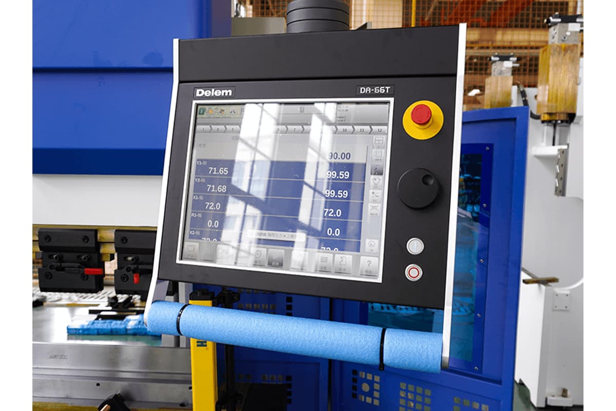
- Ensure that the control system, including any CNC components, is properly configured. Confirm that the machine is responding to commands by checking for error messages on the control panel.
5.3 Specific Troubleshooting Steps You Can Take
Once the initial checks are complete, proceed with more detailed troubleshooting of the hydraulic, electrical, and mechanical systems.
Hydraulic System
- Inspect Hydraulic Valves and Cylinders: Check for whether the valve is stuck and ensure the cylinders are functioning properly. Any stuck or damaged valves may need to be replaced.
- Check for Hydraulic Leaks: Inspect all hoses, seals, and connections for signs of leaks. Tighten fittings and replace worn-out seals as necessary.
- Test Hydraulic Pump Performance: Ensure the pump is generating sufficient pressure. If it’s underperforming, replace it.
Mechanical Components
- Inspect the Ram, Guide Rails, Bearings, and Moving Parts: Look for misalignment, excessive wear, or blockages. Lubricate or replace components as needed to maintain smooth operation.
- Examine Tooling Alignment: Verify that the upper punch and lower die are properly aligned and free from damage. Mismatched or worn tooling can obstruct the press brake ram’s movement.
Electrical System
- Test Motor and Drive System: Use diagnostic tools to check the motor’s performance and ensure it is operating normally. Look for signs of overheating or unusual noise that could indicate mechanical failure.
- Inspect Sensors and Limit Switches: Ensure that sensors and limit switches are functioning properly. Faulty sensors may send incorrect signals, preventing the machine from operating correctly.
- Reset the Control Panel: If the machine is unresponsive, try resetting the control panel to clear any errors and restore normal operation.
Ⅵ. Mechanical Causes and Solutions
6.1 Hydraulic Bending Machine System Malfunctions
- Hydraulic oil leakage: hydraulic oil leakage may be caused by seals worn or damaged. Regular checking and replacing seals and keeping hydraulic oil clean is the key. If the leakage is found, repair it immediately, and ensure the hydraulic oil is added correctly.
- Hydraulic pump: the hydraulic pump is the heart of the hydraulic system. The failure may result from the pump being worn or pressure lack. Regularly check the state of the hydraulic pump, replace the components when necessary, and ensure the pressure is within normal range.
- The hydraulic line blocked: the blocked hydraulic line affects the flow of the fluid, resulting in machine's optimal performance decreasing. Regular cleaning and maintaining the hydraulic line ensures the hydraulic fluid is smooth.
6.2 Mechanical Failures
- Bending rod problem: press brake bending rod bears large pressure and stress. The rod's abrasiveness and damage probably lead to inaccurate bending. Regularly check the press brake bending rod, making sure it is in good condition, and replace it when necessary.
- Ram and guide rail failure: ram and guide rail are important parts of the press brake, which are responsible for keeping the material stable. Damage or incorrect lubrication may lead to ram blocking or offset the rail. Regularly lubricating and checking the state of the ram and guide rail is the key to precaution the problem.
- Electrical component failure: mechanical failures are probably related to electrical components, like motors, sensors, or controllers. Regularly check electrical system connectivity and status, ensuring all the operation is normal.
6.3 Regular Maintenance Tips
- Checking regularly: establish a regular machine checking plan, including the mechanical system, mechanical components, and electricity system. Finding the problem early and repairing instantly can avoid mass-scale failure.
- Cleaning and lubricating: keep the machine clean, and lubricate the hydraulic system and mechanical components regularly to avoid friction and abrasiveness.
- Training the operator: ensure the operators accept the proper training, know the machine's normal movement and possible failure situation, and how to take appropriate approaches.
Ⅶ. Electrical Causes and Solutions
7.1 Electrical Component Failures
- Cable and wiring issues: the cable may be broken, poorly connected, or damaged, resulting in electrical malfunction. Check the integrity of cable and wire, ensuring their safe connection without wear or damage.
- Electrical components aging: Long-time use and abrasiveness may lead to electrical aging, such as relays, switches, and cable plugs. Check the state of the electrical components, and replace the aging ones when necessary.
- Power problem: power supply problems, such as voltage unstable or current load overloading, lead to electrical failure. Ensure all the equipment can be connected to stable power, and use the power protective equipment according to your needs.
7.2 Troubleshooting Electrical Issues
Shut down and ensure safety: the power supply must be cut off before maintaining any electrical issues to assure the operators’ safety.
Preliminary judgment: judge the probable trouble area preliminarily according to failure phenomenon (equipment unstarting, unusual movement, alarm displaying).
Detailed checking: check the probable malfunction area in detail. Check whether the connector is loose, the cable is damaged, and switches, relays, contactors, and other components are intact.
Test and verify: use the test tools to test the suspected components singly or combinationly to ensure the failure source.
Repair and replace: once the malfunction point is found, repair or replace the damaged electrical components in a timely, and restore the system's normal operation.
7.3 Preventative Electrical Maintenance
- Checking regularly: establish a plan for checking the electrical components’ state, including cable, plug, relay, and switch.
- Cleaning and maintenance: keep the electrical components clean, and avoid debris or dust accumulation. Clean the cable, plugs, and relay contacts.
- Electrical training: offer basic electrical training for the operators, making them recognize the common electricity problem and adopt the appropriate approaches.
Ⅷ. Software and Control System Errors
8.1 Identifying Software-Related Issues
- Abnormal operation interface: if your press brake operation interface displays abnormal or false information, this may be an obvious software problem phenomenon.
- Control system in reaction: when the equipment is started or stopped, if the control system doesn’t react or react slowly, this may be caused by software failure.
- Output unstable: abnormal output, such as unstable bending angle or size, which may result from the control system or software.
8.2 Resetting and Updating Control Systems
- Reset the system: try to reset the control system, which can be achieved by closing the power, waiting for a few minutes, and resetting. This can clear some instant problems.
- Update the software: check whether there is available software to be upgraded. The manufacturer usually releases fixed and improved software versions. The known problems can be solved by upgrading.
- Restore default settings: if the software problem can not be solved, the control system can be restored to the factory default settings, and reset it.
8.3 When to Seek Professional Help for Software Problems
- Problems can not solved: manufacturers or professional support may needed if the problems are still here after the above procedures are tried.
- Safety problem: if the software problem threatens the safety of operators or breaks the equipment, the equipment should not be used, and assistance is needed.
- Authorized maintenance personnel: it is better to connect the authorized maintenance personnel or manufacturing technique supporting teams to handle the software or control system problems when the relevant skills and knowledge are short.
For a practical, visual walkthrough of troubleshooting and resolving these types of issues on specific systems, view our detailed tutorial: How to Correct Errors on an Electro Hydraulic Press Brake DA 53TX& DA 58TX.
Ⅸ. Maintenance and Preventive Measures
9.1 Regular Maintenance Practices
Hydraulic System Maintenance
- Oil Quality and Levels: Check the hydraulic oil regularly to ensure it is clean and at the proper level. Replace the oil according to the manufacturer's schedule to prevent contamination and maintain optimal pressure.
- Filter Replacement: Regularly inspect and replace filters and strainers to prevent blockages and maintain optimal system performance.
- Leak Inspection: Check hoses, seals, and connections routinely for any signs of leaks. Promptly replace damaged components to prevent pressure loss.
Mechanical Component Care
- Lubrication: Regularly lubricate guide rails, bearings, and moving parts to reduce friction and wear. Use manufacturer-recommended lubricants for optimal results.
- Tooling and Guide Rail Maintenance: Inspect tooling for wear, and check guide rails for alignment and condition. Replace worn components to ensure accurate bending and smooth ram movement.
Electrical System Checks
- Wiring Inspections: Inspect the electrical wiring for damage, loose connections, or exposed wires. Replace or secure damaged components to prevent operational disruptions.
- Sensor Testing: Test sensors and limit switches to ensure proper functionality. Replace faulty components to maintain precision and safety.
- Control Panel Updates: Keep the control system software up-to-date. Address system alerts or error codes promptly to avoid disruptions.
9.2 Preventive Measures
System Calibration
- Ram Parallelism: Check and adjust ram parallelism regularly to ensure even pressure during operations. Misalignment can lead to defects in the workpiece and unnecessary strain on the machine.
- Tool and Die Alignment: Confirm the alignment of the punch and die before starting operations to achieve accurate and consistent bending results.
Environmental Considerations
- Temperature Control: Ensure the hydraulic system operates within the recommended temperature range to avoid overheating. Use cooling systems or fans if necessary.
- Clean Operating Environment: Maintain a clean working environment by keeping the machine and surrounding area free of dust and debris to prevent contamination of hydraulic oil and mechanical components.
Operational Best Practices
- Proper Loading: Do not overload the press brake beyond its rated capacity to protect the hydraulic system and frame.
- Routine Checks: Perform daily checks, including verifying oil levels, inspecting tooling, and testing the control system, to identify potential issues early.
9.3 Scheduled Inspections
Conduct detailed inspections of hydraulic, mechanical, and electrical systems at regular intervals as recommended by the manufacturer. For complex issues or scheduled overhauls, consider professional servicing by certified technicians.
Ⅹ. Advanced Troubleshooting Techniques
10.1 Diagnosing Software and Control System Issues
Effective troubleshooting starts with examining the software and control systems, as modern press brakes depend on precise digital control for smooth operation.
- Error Codes and Diagnostics: Start by using the machine's built-in diagnostics or CNC control system to identify any error codes. Refer to the manufacturer's manual for details on the codes and recommended actions.
- Control System Calibration: Make sure the CNC control system is correctly calibrated. Misconfigured settings, such as bending force, stroke length, or return settings, can prevent the ram from moving properly.
- Firmware Updates: Check for available firmware or software updates from the manufacturer to fix bugs or improve performance.
10.2 Handling Complex Hydraulic Problems
Hydraulic issues often require specialized tools and expertise to resolve. Here’s how to approach the most common hydraulic problems:
- Stuck or Malfunctioning Valves: Remove and clean any malfunctioning hydraulic valves, especially solenoid or proportional directional control valves, and test their operation with a multimeter to ensure proper electrical response.
- Pressure Testing: Use a hydraulic pressure gauge to check the pressure at different points in the system. This helps identify any irregularities in the oil pump, cylinders, or pressure relief valves.
- Cavitation or Aeration: Look for signs of cavitation (bubbles caused by low pressure) or aeration (air leaks) in the hydraulic system. Bleed the system, replace worn seals, or correct the pump operation to eliminate these issues.
10.3 Resolving Mechanical Alignment Issues
Misalignment can cause significant operational problems in a press brake, and correcting it often requires careful adjustments.
- Ram Alignment: Check that the ram is properly aligned with the bed. If it's misaligned, adjust the eccentric sleeves or use leveling tools to restore alignment.
- Guide Rail Adjustments: Inspect the guide rails for wear or improper tension. Tighten or replace pressure plates as necessary to ensure smooth ram movement.
- Component Replacement: Replace worn components like bearings, bushings, or guide rails that cannot be realigned effectively.
10.4 Addressing Advanced Electrical Faults
Electrical issues can be complex, but they can often be traced to key components.
- Signal Verification: Test the continuity of electrical signals to key components like limit switches, motors, and solenoid valves. Use a multimeter to detect wiring breaks or weak connections.
- Motor Testing: Use a megohmmeter to test the motor's windings and insulation resistance. Replace any motor that shows signs of wear, overheating, or electrical faults.
- Control Panel Issues: Check the control panel for loose connections, damaged circuits, or unresponsive buttons. Repair or replace faulty components as needed.
10.5 Guidelines for Engaging Professional Support
Some issues can be resolved in-house, but others require professional help.
- Manufacturer Support: Reach out to the press brake manufacturer for guidance on resolving complex issues, particularly those related to proprietary software or components.
- Certified Technicians: For advanced mechanical repairs, hydraulic troubleshooting, or electrical diagnostics that require specialized tools, engage a certified technician.
- Replacement Parts: Use genuine replacement parts from the manufacturer to ensure compatibility and reliability.
10.6 Preventing Recurrence of Advanced Issues
Once repairs are made, take steps to reduce the risk of future issues.
- Comprehensive Testing: After repairs, perform a full diagnostic test, including operational trials, to confirm that all systems are functioning properly.
- Documenting Repairs: Keep detailed records of repairs, including replaced parts and updated settings. This documentation is invaluable for future maintenance or troubleshooting.
- Advanced Operator Training: Train operators on best practices, focusing on load limits, daily checks, and spotting early signs of problems.
XI. Preventive Maintenance: Building a “Zero Downtime” System
The most effective form of maintenance is the kind that makes maintenance unnecessary. When we shift our mindset from “how to fix it” to “how to keep it from breaking,” we move from reactive repair to proactive reliability. This transformation marks the true beginning of equipment management excellence. From responding to failures to eliminating root causes, this is not just a methodological shift—it’s a philosophical one. This chapter will guide you through building a complete maintenance pyramid, from daily inspections to full annual overhauls, and reveal how rigorous control over your machine’s “lifeblood” (its working fluids) and human operations can eliminate most unplanned downtime at the source.
5.1 The Ultimate Maintenance Checklist: From Daily Inspections to Annual Overhauls
An unstructured maintenance plan only produces random failures. A systematic maintenance checklist, however, guarantees consistency—it turns preventive care into second nature. This checklist strategically breaks complex maintenance tasks into four interconnected time-based layers.
Daily Checks: The Operator’s Five-Minute Pre-Shift Ritual
This is the first—and most crucial—line of defense in your prevention framework. It’s designed to catch 80% of visible issues at minimal cost.
- Hydraulic system inspection (“look, listen, question, and feel”): Check that the oil level in the reservoir is within the normal range.
Deep insight: Don’t merely glance at the level—observe the oil’s “complexion” like a doctor checking a patient’s blood color. Healthy hydraulic oil should be clear and bright. A milky appearance indicates water contamination, cloudiness suggests solid particles, and excessive foaming means air ingress—all serious warning signs that require immediate shutdown and investigation. - Safety device verification: This is a non-negotiable daily rule. Fully test the emergency stop button, intentionally block the safety light curtain, and open and close the safety door once. Watch to confirm each protection feature responds instantaneously and flawlessly. This is the ultimate expression of respect for life.
- Listening for abnormal noises or movements: Start the oil pump and listen closely for unusual sounds—especially sharp hissing (a sign of cavitation) or irregular clicking (possible internal wear). In no-load mode, run the slide and back gauge through a full stroke, and feel for smooth, consistent motion without hesitation or vibration.
- Visual inspection and cleanliness: Walk around the machine to spot new oil leaks (especially around cylinder seals and valve joints), loose guards, or unusual wear marks. Keep the mold area and control panels clean, and remove metal debris promptly—not only for appearance but to prevent short circuits and mechanical interference.
Weekly Checks: Deepening and Reinforcing Basic Maintenance
- Clean the “respiratory system”: Use compressed air to thoroughly clean the dust filters on the electrical cabinet and hydraulic station cooling fans. A clogged filter is like forcing a marathon runner to wear a mask—it’s the leading cause of component overheating and accelerated aging.
- Fastener inspection: Vibration is the enemy of all bolted connections. Pay special attention to the tightness of mold clamps, backgauge drive components, and primary structural connections. Address any looseness before it becomes a problem.
- Die condition check: Inspect the edges of frequently used upper and lower dies for chipping or wear. Clean all die surfaces and seats with a lint-free cloth to ensure absolute cleanliness during die changes.

Monthly Checks: Comprehensive System Diagnostics
- Precision lubrication of guideways: Following the equipment manual, add the specified grade and viscosity of way oil to the lubrication points (grease nipples or centralized systems) on both sides of the slide.
Best practice: After applying oil, manually operate the slide through several full strokes to spread the oil evenly across the entire contact surface, forming a resilient protective film. - Hydraulic system health assessment: Inspect all hydraulic filter contamination indicators (pressure gauges or pop-up indicators). If an indicator signals blockage, the filter is nearing capacity and must be replaced immediately—don’t gamble on system safety.
- Electrical Cabinet “Deep Clean”: After strictly following the LOTO procedure, open the electrical cabinet. Use dry, low-pressure compressed air or a professional electronics cleaning brush to remove dust from internal components. Visually inspect contactors and relay contacts for signs of blackening or pitting, and check all terminal connections for looseness or discoloration caused by overheating.
Annual Major Maintenance: A Complete “Genetic-Level” Overhaul and Renewal
- Hydraulic System “Blood Purification”: It’s generally recommended to replace the hydraulic oil and all filters thoroughly every 2,000–4,000 operating hours, or at least once a year.
Key Insight: The essence of oil replacement lies not in “changing” but in “cleaning.” After draining the old oil, meticulously clean the bottom of the tank using specialized tools and lint-free cloths to remove sludge, metal particles, and other “toxins.” Failing to do so will contaminate the new oil immediately upon refill, greatly reducing the effectiveness of maintenance. - Electrical System “Thermal Imaging Scan”: This technology allows you to see potential failures before they happen. When the machine operates at full load, hire a specialist to use an infrared thermographic camera to scan breakers, contactors, frequency converters, and terminals inside the electrical cabinet. Any localized “hot spot” indicates a likely point of failure—giving you weeks or even months of advance warning to act before damage occurs.
- Mechanical Accuracy “Calibration and Restoration”: Over time, mechanical precision naturally drifts. Use high-precision instruments such as a laser interferometer or granite square to measure and calibrate the parallelism between the ram and worktable, ram repeatability, and backgauge positioning accuracy. This process restores the machine to its factory-level peak performance.
- Control System “Digital Backup”: Create a complete, reliable backup of all CNC controller parameters, PLC programs, compensation data, and user programs. These files are invaluable if the system crashes or hardware fails.
11.2 Core Insight: Treat Hydraulic Oil as the Machine’s “Blood” and Manage Its Health
Most factories focus only on regular oil replacement—a crude and costly maintenance approach. Truly proficient managers go beyond that, performing periodic “blood tests” (oil analyses) to manage equipment health through data-driven maintenance.
- Beyond Oil Changes: The Strategic Value of Regular Oil Analysis Oil analysis transforms invisible internal wear into a readable diagnostic report that reveals:
- The “Crime Scene” of Wear: By analyzing the type and concentration of metallic elements in the oil (such as copper, iron, lead, or aluminum), you can pinpoint which components are wearing abnormally—like a forensic expert. For example, a spike in copper may indicate wear on the piston pump slipper or bushings, while excess iron could point to bearings, gears, or cylinder walls. This enables preemptive maintenance before pump failure contaminates the entire system with metallic debris.
- The Source of Contamination: Measuring moisture and silicon (a key dust component) levels will clearly show whether seals are compromised or air filters are failing.
- The Oil’s Own “Health Status”: Examining viscosity, acid number, and additive depletion helps determine whether the hydraulic fluid remains serviceable. This prevents equipment damage from degraded oil while avoiding the waste of premature oil replacement.
- How to Read the Report Like an Expert:
- Water Content: The alert threshold is 500 ppm. Once exceeded, the oil emulsifies, drastically reducing lubrication performance and accelerating corrosion.
- Particle Count (ISO 4406): The gold standard for cleanliness, expressed as three numbers (e.g., 21/18/16). The smaller the numbers, the cleaner the oil.
- Kinematic Viscosity: The variation from the new oil specification should not exceed ±10%. Too low leads to oil film breakdown and severe wear; too high increases energy consumption and slows system response.
11.3 Avoiding Operational Pitfalls: Eliminating Human Errors at the Source
No machine, however robust, can withstand reckless operation. Empowering operators and standardizing procedures is the most cost-effective and high-return component of a preventive maintenance system.
- Training Focus: Avoid Overloading and “Off-Center Loading”
- Overloading: This is the most direct form of mechanical abuse—causing structural damage to the frame, cylinders, and dies—and must be absolutely prohibited.
- Off-Center Loading: The most common, subtle, and destructive “slow killer” of machines. When operators repeatedly bend small workpieces on one side of the ram, the two hydraulic cylinders and guide rails experience uneven loading. Over time, this leads to accelerated wear on one side, synchronization errors, premature seal failure, and even permanent deformation of the ram. Core Principle: Operators must be trained to align bending forces as close to the machine center as possible. For small parts, place them symmetrically or move them toward the center for balanced processing.
- Awareness Building: Transform Operators into the “First Line of Defense” for Equipment Health Empower operators to shift from mere machine users to proactive health monitors. Train them to spot and immediately report early warning signs such as:
- Unusual Sounds: The machine no longer sounds like it did yesterday—often the first and most sensitive indicator of trouble.
- Reduced Speed: The ram’s up or down motion slows noticeably, even though no parameters were changed.
- Higher Temperature: The motor or oil tank surface feels unusually hot to the touch.
- Precision Drift: Bending angles become inconsistent or erratic without an apparent cause.
- Standardized Procedures: Reinforce Proper Startup, Shutdown, and Mold-Change Habits
- Startup Procedure: Turn on the main power first, then start the hydraulic pump. In cold conditions, allow the machine to idle for 10–15 minutes to preheat. Once the oil temperature returns to the normal range, begin operations. This simple step significantly reduces wear on hydraulic components in low temperatures.
- Shutdown Procedure (A Detail Worth Its Weight in Gold): Never shut down with the ram suspended in the air! The correct method is to lower the ram gently onto the lower die or a dedicated support block before powering off. This relieves all hydraulic pressure, letting seals rest in their natural, relaxed state—greatly extending their service life.
- Mold Change Procedure: Create and display a pictorial Standard Operating Procedure (SOP) for die changes. Include key steps such as cleaning the die base, proper tool alignment, and diagonally tightening clamps in sequence. This process-driven approach prevents mold or machine damage caused by improper die replacement.

XII. Conclusion
Our passage deeply talks about the troubleshooting and performance optimization of the press brake and sheet metal equipment, emphasizing analyzing the common issues and solutions of the hydraulic system, mechanical equipment, electrical system as well as software control.
Through maintaining the good condition of the equipment and the high-level technique skills of the operator, you can largely minimize downtime, reduce repair costs, and improve stability and competitiveness. So, investing in maintenance and training is the key to ensuring the successful operation of the press brake and sheet metal equipment. To learn more about our solutions, download our brochures or contact us today for a personalized consultation.


