I. Introduction
The press brake is a machine used for sheet metal fabrication. There are a variety of press brakes, such as manual press brakes, mechanical press brake, CNC press brake, electro-hydraulic synchronous press brakes, and electric press brake. Currently, the most popular type of press brake is CNC press brake, also called an electrical hydraulic servo press brake.
The servo system and linear scale of the electrical hydraulic servo press brake can control the accuracy of the machine during operation. In the world of metal fabrication, the CNC control system can set all bending parameters to ensure the accuracy of the bending program.
The press brake structure and components are basically the same, merely differences in driving sources and individual sheet metal parts. Next, we will take the CNC press brake machine as an example and provide a detailed description of its key components and structures of a press brake.
II. Core Structural System: The Source of Rigidity and Stability
If the power system is the heart of a press brake and the CNC system its brain, then the core structural system—composed of the frame, bed, and ram—is undoubtedly its skeleton. This assembly forms the physical foundation for every aspect of machine performance. It must silently bear tremendous operational forces while providing an unshakable, deformation-free reference for all precision movement components. A deep understanding of this system marks the dividing line between routine operators and advanced engineers—and is the first step toward smart purchasing decisions. For those aiming to master precision bending mechanics, Understanding Press Brake Metal Bending offers valuable insights into force distribution and compensation during bending.
2.1 Frame: The Motionless Backbone That Bears All Pressure
The frame is the immovable backbone of a press brake. Usually fabricated from thick, high-strength steel plates, its primary mission is to minimize deformation under bending forces that may reach tens or even thousands of tons. Even minute, visually undetectable deflections can translate into significant angular errors in the finished product.
To choose the right frame configuration for your application, it's important to consider your target material and production capacity — whether a hydraulic or electric system is more suitable. Learn more in Hydraulic vs Electric Press Brake.
2.1.1 Structural Showdown: Advantages and Applications of C-Frame vs. O-Frame
Press brake frames generally fall into two categories: C-frame and O-frame (also referred to as G-frame or closed frame). The choice between these structures directly defines the machine’s operational scope and its ultimate precision potential.
| Characteristic | C-Frame | O-/G-Frame |
|---|---|---|
| Structural Form | Side profile shaped like a “C,” with an open throat and single-side support. | Side profile shaped like an “O” or “G,” composed of two vertical columns and upper/lower beams forming a closed or semi-closed, symmetric structure. |
| Key Advantage | Excellent side accessibility: the open throat allows processing of long sheets exceeding the width between side columns or enables special lateral feeding operations—highly flexible. | Exceptional rigidity and resistance to deformation: the closed design distributes bending forces evenly, minimizing deflection; ideal for high-tonnage, high-precision applications. |
| Intrinsic Limitation | Asymmetric deformation (“mouth opening” effect): under heavy load, the open side tends to spread like an opening mouth—a nonlinear response and inherent physical limitation. | Restricted side access: the side columns limit workpiece width and reduce flexibility for special long sheet operations. |
| Typical Applications | Medium-to-small tonnage operations requiring flexibility and frequent tool changes, such as small workshops, prototyping, or variable-size box fabrication. | High-tonnage, large-size, high-precision production lines—ideal for thick plate and high-strength steel processing, and industries demanding extreme straightness (e.g., aerospace, curtain wall manufacturing). |
| Expert Insight | Throat depth is a critical yet often misunderstood parameter. It not only defines the maximum insertion depth of the sheet but also correlates directly with frame “mouth-opening” deformation. Greater depth improves accessibility but reduces rigidity at equal tonnage, demanding a more advanced deflection compensation system. | A high-quality O-frame is a long-term investment in precision. Though initial cost is higher, its superior structural stability ensures lower maintenance, extended tooling life (due to uniform force distribution), and consistently high precision output. |
2.1.2 Materials and Craftsmanship: Welding Standards, Stress Relief, and Vibration Damping in Premium Frames
A top-tier press brake frame is far more than a collection of steel plates—it represents a sophisticated manufacturing process that defines quality differentiation in the market.
(1) Material Selection
High-strength, low-alloy structural steels such as Q235 and Q345 (equivalent to ASTM A572 Grade 50) are typically used. Yet the steel grade alone isn’t the decisive factor—melting quality and internal uniformity of thick plates are equally critical.
(2) Welding Process
Automated welding methods such as Gas Metal Arc Welding (GMAW/MIG) or Submerged Arc Welding (SAW) ensure continuous, deep welds. Weld design and orientation are optimized through Finite Element Analysis (FEA) to avoid high-stress zones.
(3) Stress Relief
The cornerstone of long-term structural stability—often neglected by low-cost manufacturers. Welding introduces significant residual stresses due to localized heating and cooling. If these remain unrelieved, they will gradually release during machining and operation, causing unpredictable micro-deformation and permanent loss of accuracy.
1)Thermal Aging (Annealing): The entire welded frame is placed in a large furnace, slowly heated to around 600–650°C, held for several hours, then cooled down extremely gradually. This is the most thorough and effective method, though energy-intensive and costly.
2)Vibratory Stress Relief (VSR): By mounting vibrators at specific points, the frame resonates, redistributing and relaxing internal stresses via vibration energy. This modern, energy-efficient method demands significant technical expertise and operational experience.
(4) Vibration Damping Design
Rapid acceleration and deceleration create unavoidable vibrations. A lesser-known yet highly effective technique is to fill the enclosed cavities of the frame with quartz sand or specialized composite materials. These loose particles absorb vibration energy through friction, converting it to heat—significantly enhancing dynamic stability.
2.1.3 Rigidity Evaluation: How Frame Stiffness Directly Impacts Bending Precision and Equipment Longevity
Frame rigidity is not an abstract concept—it’s quantifiable as the deformation magnitude per unit of applied pressure.
(1) Impact on Bending Precision
Insufficient frame rigidity is the fundamental cause of inaccurate bending angles. If the frame’s deformation under varying loads is unstable or nonlinear, even advanced deflection compensation systems cannot precisely predict and offset the error, leading to inconsistencies between the workpiece’s center and ends.
(2) Impact on Equipment Lifespan
Repeated deformation cycles induce metal fatigue. Frames with poor rigidity continuously “strain” under heavy loads, accumulating fatigue in high-stress areas (such as welds and corners). Over time, microcracks may form, eventually resulting in permanent deformation and irreversible damage to the ram and bed.
2.2 Bed (Lower Beam): The Stable Foundation Supporting the Lower Die
The bed serves as the reference platform for mounting the lower die and, together with the ram, bears all the bending forces. Its design goal is to maintain absolute straightness and stability under massive loads.
2.2.1 Structural Design: Standards and Functions of Stiffening Ribs, T-Slots, and Clamping Surfaces
(1) Stiffening Ribs
The bed is not solid; instead, a complex network of welded ribs enhances bending resistance. Rib configurations and dimensions are precisely optimized through Finite Element Analysis (FEA) to achieve maximum rigidity with minimal material use.
(2) T-Slots
The bed’s T-slots not only secure the lower die but also form the foundation for modular functionality in modern press brakes. Their dimensional precision and straightness are critical, providing the reference interface for deflection compensation systems, multi-V dies, and specialized tooling.
(3) Clamping Surface
The contact area between the worktable and the lower die must be ground to a high level of precision. Perfect flatness is essential to ensure the die is evenly and securely supported. Any unevenness can cause a minute tilt under load, directly affecting the accuracy of the bending angle.
2.2.2 Deflection and Deformation: Understanding how the worktable physically bends under load and how it impacts accuracy
Deflection is a fundamental and unavoidable physical phenomenon in press brake engineering. Because the power source (hydraulic cylinders) is positioned on both sides while the bending force acts mostly at the center, the worktable and ram behave like a bridge under load—the center sags downward, producing deflection.
(1) “Canoe Effect”
This deformation, where the center sinks and the ends lift, causes the middle section of the workpiece to bend less deeply than the edges. As a result, the finished part forms a larger angle in the center and smaller angles at both ends, resembling a canoe’s profile. For long parts, such deviation can be critically detrimental.
(2) Magnitude of Deformation
Even a seemingly insignificant longitudinal flatness deviation of just 0.06 mm on the worktable can result in a 0.17° variation in a 90° bend. This is precisely why a deflection compensation system is essential—to counteract this intrinsic physical tendency. The detailed mechanism will be explored in subsequent sections.

2.3 Ram (Upper Beam): The Precision Executor of Power Transmission
The ram, which holds the upper die, is the moving component that transmits immense power from the drive system to the workpiece with exact precision. Its design focuses not only on rigidity but also on maintaining impeccably accurate motion.
2.3.1 Guide System Analysis: From Traditional Ways to Precision Linear Guides — Ensuring Perfectly Parallel Motion
The ram's ability to maintain perfectly vertical movement despite substantial lateral forces relies entirely on its guiding system.
(1) Traditional Slideways
Earlier or low-cost machines typically adopted rectangular slideways, using bronze wear strips or hardened steel plates as sliding surfaces. This setup offers simplicity and strong load-bearing capability, yet suffers from high friction and clearance gaps. Such gaps reduce repeat positioning accuracy and expand over time due to wear.
(2) Precision Linear Guides
The standard configuration for modern high-accuracy CNC press brakes. Each guide consists of a rail and a carriage with internal circulating balls or rollers, offering extraordinary advantages:
- Zero or Negative Clearance (Preload): By using slightly oversized rolling elements, preload is achieved, fully eliminating play between rails and carriages. This dramatically enhances stiffness and positioning precision.
- Ultra-Low Friction: Rolling friction replaces sliding friction, reducing the force required to drive the ram, enabling faster response, lower energy consumption, and smoother motion.
- Long Service Life and Low Maintenance: Thanks to minimal wear, combined with advanced sealing and lubrication systems, the guide’s accuracy lifespan far exceeds that of traditional slideways.

2.3.2 Structure and Connection: The Ram’s Rigid Design and Its Linkage with the Power and Die Systems
The ram itself features a box-type or honeycomb welded structure optimized through finite element analysis (FEA) to achieve maximum bending and torsional rigidity with minimal weight. It connects to the piston rods of the hydraulic cylinders on both sides via ball joints or adjustable couplings, allowing precise alignment calibration between the ram and worktable during setup.
The lower portion of the ram houses the upper die clamping system, where clamping accuracy and holding force directly determine bending stability and safety.
In summary, the frame, worktable, and ram form the fundamental “M”-shaped core of a press brake. Their design integrity, material quality, manufacturing precision, and assembly accuracy collectively define the machine’s inherent “DNA.”
This mechanical foundation underpins all subsequent precision control systems—any compromise at this structural level cannot be perfectly corrected by later “software” or compensation methods.
Ⅲ. The Power Heart: Principles and Strategies for Drive System Selection
If the frame represents the skeleton of a press brake, then the drive system is its powerful heart. It determines the machine’s speed, output force, and control accuracy. Each drive type imparts a distinct character and capability to the press brake. Understanding them is key to making the right technical investment and application decisions. The mainstream drive technologies available today are hydraulic, electric servo, and mechanical—each optimized for specific operational requirements rather than a simple hierarchy of superiority.
3.1 Hydraulic Drive System: The Industry’s Workhorse
Hydraulic drive systems—particularly modern electro-hydraulic servo synchronization technology—remain the most mature and widely used solution on the market. Their unmatched power output and exceptional control flexibility make them dominant in medium- to high-tonnage press brake applications.
3.1.1 Core Components Breakdown: Dual Cylinders, Hydraulic Pump, Servo Proportional Valves, Manifold Block, and Circuit System
A modern electro-hydraulic servo system goes far beyond traditional hydraulic loops—it’s an integrated mechatronic system combining power generation, precision control, and real-time feedback.
(1) Dual Hydraulic Cylinders
Symmetrically mounted on both sides of the frame, they directly deliver power. Each cylinder independently drives one end of the ram (defined as the Y1 and Y2 axes), establishing the physical foundation for high-precision synchronous control.
(2) Hydraulic Pump
Typically a high-efficiency variable displacement piston pump driven by the main motor. It converts mechanical energy into pressurized hydraulic fluid energy, continuously supplying the force required for bending.
(3) Electro-Hydraulic Proportional Servo Valves
These are the core components enabling micron-level precision. Receiving minute electrical signals from the CNC controller, they precisely regulate hydraulic fluid flow and pressure into each cylinder with exceptional frequency response and linearity. This allows smooth control of ram speed, position, and tonnage output. Each cylinder (Y1 and Y2) is governed by its own dedicated servo valve.
(4) Hydraulic Manifold Block
A compact block integrating numerous hydraulic elements—directional, pressure, and throttle valves—into one assembly. This design drastically reduces piping connections, minimizing leakage risk, accelerating system response, and simplifying maintenance.
(5) Hydraulic Circuit
Comprising oil tank, high-pressure piping, filters, and coolers. The tank stores oil and aids in heat dissipation; precision filters act as the system’s “kidneys,” removing impurities and protecting costly servo valves; the oil cooler ensures temperature stability, preventing viscosity fluctuations that can affect bending accuracy.
3.1.2 Operating Principle: How Hydraulic Pressure Converts into Tonnage and Enables Y1/Y2 Axis Synchronization
The essence of hydraulic drive technology lies in the grand application of Pascal’s Principle combined with the sophistication of modern closed-loop feedback control.
(1) Pressure Generates Tonnage
The CNC controller issues commands, activating the motor-driven pump to produce high-pressure oil. The servo valve opens to a specific degree, supplying fluid to the upper chamber of the cylinder. According to the formula Force = Pressure × Area, the large piston surface multiplies the oil pressure (measured in PSI or Bar) thousands of times, transforming it into the immense tonnage capable of plastically deforming high-strength steel plates.
(2) Y1/Y2 Axis Synchronization Control (High-Precision Closed Loop)
This is the key distinction between modern electro-hydraulic servo press brakes and traditional torsion-bar synchronized machines—and the foundation of their exceptional accuracy.
1)Independent Measurement: High-precision linear scales mounted on the C-frames at both sides of the machine independently measure, in real time, the exact position of the ram’s left and right ends (Y1, Y2) relative to the worktable, with a resolution as fine as 0.001 mm.
2)Real-Time Comparison: The CNC controller continuously compares, hundreds of times per second, the actual position feedback (Y1, Y2) from the scales against the programmed target values.
3)Dynamic Correction: If any minute deviation is detected—for instance, one side starting to drop slightly faster due to uneven loading—the CNC instantly sends correction signals to the corresponding servo valve, fine-tuning the oil flow to that cylinder to alter its descent speed until both sides match perfectly with the target positions. This measure–compare–adjust closed-loop process runs throughout the entire bending stroke, ensuring the ram maintains impeccable parallel travel. Even under severe off-center loading, it guarantees astonishing consistency of angle across the full workpiece length.
3.1.3 Pros and Cons: Balancing High Tonnage, Flexibility, and Maintenance Cost
| Advantages | Disadvantages |
|---|---|
| Unlimited tonnage: Can deliver bending forces of several thousand or even tens of thousands of tons at a relatively economical cost, making it the only viable solution for thick or high-strength steel processing. | Higher energy consumption: Even in standby, the hydraulic pump must maintain system pressure, resulting in some idle energy usage. Modern systems have improved greatly but still consume more power than servo-driven models. |
| Built-in overload protection: Hydraulic systems feature relief valves that automatically vent pressure when loads exceed the set limit, effectively protecting the machine and costly tooling from unexpected damage. | More complex maintenance: Involves oil, pumps, valves, piping, and seals; demands exceptional hydraulic oil cleanliness and carries some risk of leakage. Maintenance requires specialized expertise. |
| Highly flexible control: Ram speed (rapid advance, working speed, return), pressure, stroke, and dwell time can all be precisely programmed, enabling sophisticated bending operations. | Speed limitations: Hydraulic systems respond and cycle more slowly than electrical or mechanical drives, making them less suitable for ultra-high-speed production environments. |
| Mature and reliable technology: As the industry’s most established solution, design, manufacturing, and maintenance processes are highly standardized, with excellent parts interchangeability and service availability. | Environmental impact: Hydraulic oil is a consumable requiring periodic replacement; waste oil disposal affects the environment, and leaks can contaminate the workspace. |
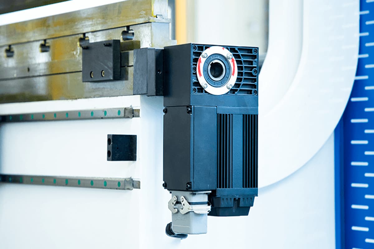
3.2 Electric Servo Drive System: The Future of Speed, Precision, and Efficiency
The all-electric servo press brake represents the most rapidly evolving technology in recent years. By replacing hydraulic systems entirely with servo motors and precision mechanical transmissions, it combines green energy efficiency, high speed, and extraordinary accuracy—triggering a genuine productivity revolution in the medium- and low-tonnage market.
3.2.1 Core Components: Servo Motors, Ball Screws, and Synchronous Belt Drive Systems
Its design is simpler and more streamlined, centered on the highly efficient conversion of electrical energy into mechanical motion:
(1) High-Torque Servo Motors
Typically two or more operate as independent power sources. Each motor contains a precision encoder, enabling millisecond-level response and tightly controlled, closed-loop regulation of speed and rotation angle.
(2) Precision Transmission System
Responsible for converting the motors’ rotary movement into smooth, backlash-free linear motion of the ram. Two major approaches are commonly used:
(3) Ball Screws
The most prevalent method. Servo motors drive large-diameter ball screws via high-strength synchronous belts. The screw nuts connect directly to the ram. With transmission efficiency exceeding 90% and minimal backlash, ball screws faithfully translate the motor’s precise rotation into micron-level linear displacement.
(4) Multi-Link or Belt Mechanisms
Certain specialized designs utilize multiple pulley groups or complex crank-link assemblies to amplify force and transmit motion, tailored for varying load and speed requirements.
(5) Load Cell
A critical yet often overlooked component. Since an electric servo system lacks the inherent pressure feedback of hydraulics, load cells must be installed at key stress points on the ram or frame to continuously monitor bending force. This real-time feedback enables precise tonnage control and overload protection via the CNC system.
3.2.2 Operating Principle: How Rotary Motion Converts Efficiently and Precisely into Linear Bending Force
Servo-driven systems operate through pure electromechanical digital control—clean, precise, and direct:
(1) The CNC controller calculates the target ram position, velocity, and required tonnage according to the program.
(2) The controller sends digital pulse commands to the servo drives on both sides.
(3) The servo motors rotate precisely at the commanded angle and speed.
(4) The motors’ rotation is transmitted via synchronous belts and ball screws, efficiently converted into the ram’s vertical linear movement.
(5) The motor’s internal encoder and the machine’s linear scale together create a dual closed-loop for position control, while the load cell forms the pressure feedback loop. This dual precision system guarantees unmatched repeatability and positioning accuracy for servo press brakes.

3.2.3 Pros and Cons: Evaluating Energy Savings, Speed, Low Noise, and Tonnage Limits
| Advantages | Disadvantages |
|---|---|
| Exceptional energy efficiency: Servo motors consume power only during motion—virtually zero standby energy use. Overall savings can exceed 50% compared with hydraulics, drastically reducing operating costs. | Limited tonnage: Constrained by servo motor capacity and ball screw load tolerance, most current models are below 200 tons and unsuitable for heavy plate forming. |
| High speed and precision: Rapid motor response and excellent acceleration/deceleration deliver cycle times up to 30% faster than hydraulic presses and repeat positioning accuracy within ±0.002 mm. | Higher initial cost: Large servo motors, drivers, and precision ball screws are expensive, making machine prices significantly greater than comparable hydraulic models. |
| Simplified maintenance: No hydraulic oil, piping, or valve blocks—eliminating leakage and contamination risks. Maintenance is minimal, offering true plug-and-play usability. | Limited overload capacity: Although protected by load cells, mechanical drive components are less tolerant of shock or overload than hydraulics, requiring strictly correct operation. |
| Low noise and eco-friendly: Extremely quiet during operation, with no continuous pump noise—ideal for modern green factory environments. | High integration complexity: Demands advanced electrical control and software expertise; troubleshooting requires highly trained technicians. |
3.3 Mechanical Drive System: The Classic High-Speed Solution for Niche Applications
Mechanical press brakes represent the oldest drive technology, using a flywheel, clutch, and crank-link mechanism to move the ram purely by mechanical force. Although their precision and flexibility fall short of today’s CNC machines, they still hold a distinct niche in specific industrial applications where their advantages remain compelling.
3.3.1 Core Component Breakdown: Flywheel, Clutch, Brake, and Crank-Link Mechanism
(1) Flywheel
Continuously driven at high speed by the motor, the flywheel serves as the machine’s energy reservoir.
(2) Clutch/Brake
These components control the engagement and disengagement of power. When the foot pedal is pressed, the clutch engages, transmitting the flywheel’s stored energy to the crankshaft.
When the pedal is released, the clutch disengages and the brake locks the crankshaft instantly, halting the ram’s movement.
(3) Crankshaft Mechanism
Converts the rotational motion of the crankshaft into the reciprocating linear motion of the ram.
3.3.2 Operating Principle: The Mechanics of Flywheel Energy Storage and Instantaneous Release
This mechanism operates with simple yet remarkable efficiency: the motor continuously drives a heavy flywheel, storing immense kinetic energy. When the clutch engages, this energy is instantly transferred to the crankshaft, powering the ram through a single, forceful stroke.
The stroke length and speed are fixed by the geometry of the crank mechanism, meaning they cannot be adjusted mid-cycle. A critical attribute—and limitation—is that once the stroke begins, it must complete the full cycle without pause or reversal, which poses a notable safety constraint.
3.3.3 Application Scenarios: Why It Still Excels in High-Volume, Single-Product Manufacturing
The chief advantages of mechanical press brakes lie in their speed and cost efficiency. Their cycle rates are exceptionally high—significantly faster than those of hydraulic presses.
For applications that demand massive throughput rather than high precision, such as producing brackets, clips, or small hardware parts, their unmatched production speed coupled with low acquisition and maintenance costs make them economically compelling choices.
3.4 [Decision Tool] Drive System Selection Matrix
To provide a clear comparison of the three main drive systems, the following matrix offers a multi-dimensional evaluation designed to support your technical decision-making. By consolidating the key parameters, this table helps you quickly identify the most suitable "power core" for your specific production needs.
| Evaluation Dimension | Electro-Hydraulic Servo System | All-Electric Servo System | Mechanical Drive System |
|---|---|---|---|
| Bending Accuracy | High (typically ±0.01 mm) | Ultra-high (up to ±0.002 mm) | Low |
| Cycle Speed | Moderate | Fastest | Fast |
| Tonnage Range | Broad (30T – 8000T+) | Narrow (usually < 200T) | Moderate |
| Control Flexibility | High (adjustable speed, pressure, stroke, dwell time) | Extremely high (finer control response) | Very low (fixed, unadjustable stroke) |
| Energy Efficiency | Moderate (standby power consumption) | Highest (on-demand operation, energy savings of 50%+) | Low (flywheel continuously idle) |
| Maintenance Cost | Medium to high (hydraulic circuits, seals, filters) | Very low (virtually maintenance-free) | Low (mechanical wear of clutch and brake pads) |
| Noise Level | Moderate (pump noise present) | Very low (quiet and eco-friendly) | High (impact and transmission noise) |
| Initial Investment | Moderate | High | Low |
| Core Strength | Ideal balance of power and versatility | Pursuit of ultimate speed, precision, and efficiency | King of speed and cost in high-volume production |
| Typical Applications | General sheet metal fabrication—from thin to thick plates, simple to complex parts | Electronics, medical devices, precision enclosures, and environments prioritizing efficiency and ergonomics | Simple hardware components, mass stamping, low-precision industries |
Ⅳ. The Precision Control Triangle: The Three Key Systems That Define Final Product Quality
If the frame and drive system represent the machine’s physical strength, then the next three systems—the back gauge, crowning compensation, and CNC control—embody its finesse and intelligence. These are not isolated components, but rather an interdependent triad forming the machine’s “precision control triangle.” Together, they determine the final product’s dimensional accuracy, angle consistency, and geometric linearity. A deep understanding of this triangle marks the dividing line between a competent operator and a true process master.
4.1 Back Gauge System: The Absolute Core of Dimensional Control
The back gauge system is the component responsible for precise positioning. What appears to be a simple fixture is, in fact, a sophisticated robotic assembly located at the rear of the machine. Its sole mission: to tell the sheet exactly where it must be bent—with uncompromising precision. It defines the flange dimensions (the distance from the bend line to the sheet edge), and its complexity and accuracy directly set the upper limit for the machine’s part complexity and production efficiency.
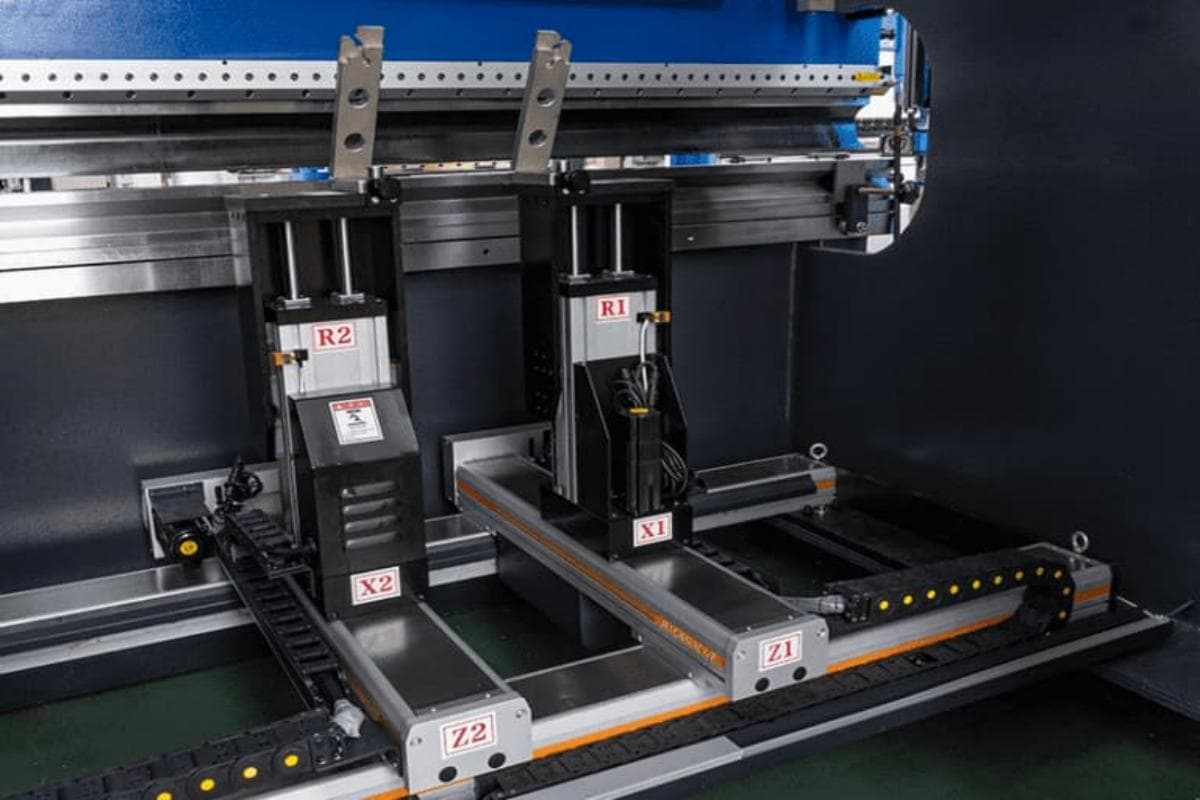
4.1.1 Multi-Axis Universe Explained: From the Basic X-Axis to Advanced 6-Axis Synchronization (X, R, Z1, Z2, Delta X), Detailed Axis Functions
Modern CNC back gauges are far more than simple stops—they are precise, multi-axis automation systems. The more axes a gauge has, the greater its positional freedom and the exponentially higher its capacity to handle complex workpieces.
| Axis Name | Direction of Movement | Core Function & Application Scenario | Expert Insight |
|---|---|---|---|
| X Axis | Forward/Backward (perpendicular to the bending line) | The fundamental and most essential axis controlling the entire backgauge's motion along the front–back direction—this defines the length of the bending flange. It’s the standard configuration for all press brakes. | In advanced systems, the X axis can be split into independent X1 and X2 axes, allowing each stop finger to move separately. This enables efficient production of tapered parts (with different flange lengths at each end) without the need for complex fixturing. |
| R Axis | Up/Down | Moves the backgauge beam vertically. Primarily used for: (1) lowering the gauge fingers to avoid interference with pre‑formed sections when processing Z‑shaped or stepped parts; (2) automatically adjusting finger height to match punches and dies of varying heights. | Independently controlled R1 and R2 axes allow each gauge finger to have different heights. When combined with X1/X2 control, this delivers highly flexible positioning for non‑parallel bend lines—crucial in the fabrication of automotive structural components or architectural nonstandard profiles. |
| Z Axis (Z1, Z2) | Left/Right (parallel to the bending line) | Enables each gauge finger to move independently along the left‑right direction. This allows automatic finger spacing based on workpiece width or bend location—eliminating manual adjustments and greatly improving efficiency when working with irregular shapes, cutouts, or multi‑stage bends. | Automated Z‑axis control is also vital for avoiding collisions with segmented top‑tool clamping plates. The CNC automatically simulates the setup, adjusting finger positions in real time to steer clear of obstacles, safeguarding both tooling and machine integrity. |
| Delta X Axis | Independent fine adjustment (front–back) for each finger | An enhancement of the X‑axis function: on top of X1/X2 separation, each finger can make a small independent front‑back micro‑adjustment (typically within ±100 mm). This provides unmatched flexibility for positioning asymmetric parts or those with localized reference features. | Imagine a part that must use a small offset protrusion as its datum—Delta X enables this kind of asymmetric, ultra‑precise positioning that a standard X axis simply cannot achieve. |
| Multi‑Axis Coordination | Spatial freedom positioning | A system combining X, R, and Z axes (4‑axis backgauge: X + R + Z1 + Z2) is already considered an advanced setup. However, a 6‑axis configuration (X1 + X2 + R1 + R2 + Z1 + Z2) allows the two fingers to reach virtually any point and orientation in the back workspace—an ultimate solution for manufacturing the most complex aerospace or medical components. | A 6‑axis system is not just an add‑on of functions; it represents a paradigm shift. The machine adapts to the complexity of the part—instead of forcing engineers to simplify designs to fit the machine’s limitations. |
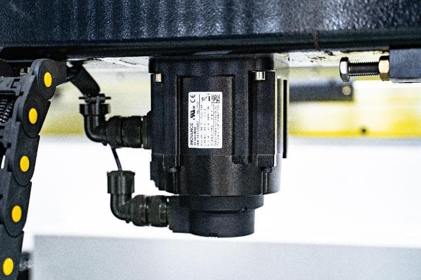
4.1.2 Structure and Drive: How Servo Motors and Linear Encoders Achieve Micron‑Level Accuracy
The backgauge’s extraordinary precision comes from its perfectly closed‑loop drive and feedback system. Each axis is powered by an independent AC servo motor, which converts rotary motion into linear motion through a high‑strength synchronous belt and precision ball screw assembly. This combination delivers transmission efficiency above 90% with negligible backlash. Positioning accuracy is maintained via closed‑loop feedback: high‑precision linear encoders or high‑resolution rotary encoders built into the servo motor continuously report the actual finger position to the CNC controller with micrometer precision. This feedback loop ensures absolute and repeatable accuracy—typically within ±0.02 mm.
4.1.3 Finger Design: Standard, Custom‑Shaped, and Sheet Support Arms
Gauge fingers—those components that make direct contact with the sheet—are equally vital in system performance.
- Standard Fingers: The most common design, featuring multiple reversible locating surfaces to accommodate various bending step heights.
- Custom‑Shaped Fingers: Required for parts where holes, cutouts, or irregular contours must serve as locating references, necessitating purpose‑built finger shapes.
- Sheet‑Following Support Arms: For large or thin flexible sheets that tend to sag or lift during bending, leading to loss of contact with the gauge and inaccurate positioning. These support arms (typically mounted at the front but working in sync with the backgauge) rise and fall with the sheet throughout the bending cycle, ensuring continuous support and consistent positioning accuracy.
4.2 Crowning System: An Intelligent Solution Against Physical Deflection
This is the core technology that determines the bending quality of long workpieces. Without proper deflection compensation, even the most precise machine cannot produce uniform angles across the full length. The crowning system marks the difference between a press brake that merely functions and one that achieves true precision.
4.2.1 Root Cause: Why Long Bends Tend to Have Larger Angles in the Middle
As explained earlier, when massive pressure is applied during bending, both the ram (upper beam) and the bed (lower beam) elastically deform—the center sags slightly while the ends remain in place. This phenomenon, known as deflection, causes the center section of the sheet to be bent less deeply than the ends, producing a part with a wider central angle and narrower end angles—commonly called the “canoe effect.” Such deformation seriously undermines product quality and assembly precision.
4.2.2 Comparison of Compensation Methods: From Manual Shimming to Mechanical and CNC Hydraulic Systems
To counteract deflection, engineers have developed various compensation techniques—each stage of evolution clearly traces the transformation from artisanal methods to precision engineering.
| Compensation Method | Working Principle | Advantages | Disadvantages |
|---|---|---|---|
| Manual Shimming | The most rudimentary approach. Skilled operators insert paper or thin steel sheets between the lower die and the workbench to manually raise the center area. | Nearly zero cost. | Entirely dependent on operator experience—unquantifiable, unstable, and extremely time-consuming. The adjustment process wastes materials and has been almost entirely phased out in modern manufacturing. |
| Mechanical Wedge Compensation | A set of wedges with slanted surfaces is installed inside the workbench. By turning a manual crank or using a motor drive, the wedges shift relative to each other, pushing up the worktable surface to create a subtle upward arc that compensates for deflection. | Reliable and mechanically stable with low maintenance costs. | The compensation curve is fixed, making adjustments cumbersome. It cannot adapt dynamically to varying bending forces—essentially a “static” compensation solution. |
| CNC Hydraulic Automatic Compensation | The standard feature of modern high-precision press brakes. A row of miniature hydraulic cylinders beneath the workbench is precisely controlled by the CNC system. Based on parameters such as material type, thickness, and bending length, the system uses its built-in finite element database to compute the required compensation force in real time, then adjusts each cylinder’s pressure accordingly to produce a counter-deflection curve, perfectly offsetting deformation. | Precise, dynamic, automatic: the CNC calculates and executes compensation in real time with no manual input. The curve adapts dynamically to the actual load, achieving exceptional accuracy. | Higher initial investment and periodic hydraulic maintenance required—but the performance gains easily outweigh the costs. |
4.2.3 Value Assessment: Why Automatic Deflection Compensation is the “Non-Negotiable” for High-Precision Fabrication
Automatic deflection compensation is considered indispensable for high-precision bending because it tackles the most fundamental and unpredictable challenge in the process—physical deformation. Its value lies in several key aspects:
- Ensures angle consistency: Reduces angular deviation along long workpieces from a visible ±2–3 degrees to an almost undetectable ±0.3 degrees, measurable only with precision instruments.
- Improves first-pass success rate: Transforms bending from an experience-driven “trial-and-error” approach to a data-driven “first-time-right” process. The first-bend success rate can exceed 95%, significantly cutting setup time and costly material waste.
- Reduces dependence on operator skill: Shifts complex compensation work from the realm of master operators to automated CNC control. This ensures consistent, reproducible quality so even newcomers can produce expert-level results.
- Unleashes full machine potential: Without automatic compensation, even high-tonnage, long-bed machines cannot achieve true precision bending for large components—leaving much of the machine’s capability untapped.
For any enterprise striving for precision, efficiency, and production stability, the reduction in waste and boost in throughput that come with automatic deflection compensation far outweigh the cost of the system itself. It’s not an optional accessory—it’s the key that unlocks the full value of advanced machinery.
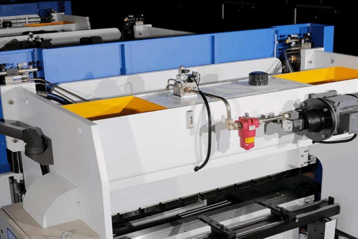
Front Support
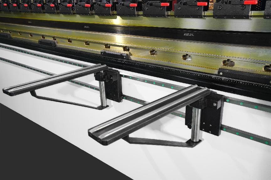
Front support is used to support metal sheet being bent and can be adjusted up and down. It is equipped with guide rails and can move automatically. It is more safer and stable compared with manual support, thus achieving better bending results.
Crane Arm
The crane arm is used to hang or support the small control box, which can be turned around in all directions. It boosts a good load-bearing press brake's capacity and a strong and solid structure. It is mostly made of high-quality aluminum alloy with open molding.
Foot Pedal
The foot pedal is one of the four main components (operator, equipment, system, foot pedal) in the operation of the press brake. It integrates emergency stop, cycle, and single-step remote control functions.
The foot pedal allows for the free control of the back gauge left and right movement, as well as the machine's start and stop functions, and integrates control of the machine tool. What’s more, it can be added with a WIFI module for networking, enabling seamless monitoring and management across the entire area, and offering simplified management capabilities.
Linear Scale
Linear scale serves for measuring and controlling the location and angle during bending process. It can be installed on the top punch or bottom die of the press brake. It is used to measure the location of top punch or bottom die accurately, and control the motion of press brake timely.
Linear scale boosts for its high precision and high definition, which can meet your expected requirements, improving the precision and stability in bending process.
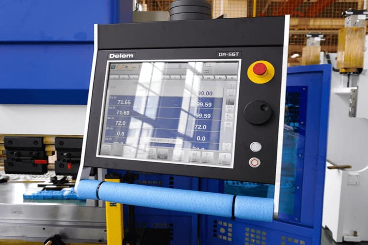
4.3 CNC Control System and Sensors: The Machine’s Brain and Nervous Network
The control system is the brain of the press brake, managing the machine's operations through an interface that allows the operator to input commands. Modern press brakes come with CNC (Computer Numerical Control) systems, providing high precision and automation capabilities.
CNC controllers, such as the Delem DA-66S or CybTouch 12 PS, offer advanced programming features, real-time monitoring, and diagnostics. These controllers enable operators to create complex bending sequences, store programs, and ensure consistent bending accuracy. For a practical demonstration, you can learn How to Program Bending with the Delem DA66S System through a step-by-step video guide.
Sensors and feedback devices play a critical role in maintaining the accuracy and safety of the press brake. These components include position sensors, pressure sensors, safety sensors.
4.3.1 Core Capabilities: Program Editing, Automatic Angle Calculation, 2D/3D Bending Simulation, and Collision Detection
Modern controllers—such as those from industry leaders DELEM, ESA, and CYBELEC—offer highly sophisticated functionalities:
- Graphical Programming: Operators can draw the 2D profile or directly import a 3D model on the touchscreen, and the system automatically generates the bending program.
- Intelligent Computation: Using an extensive material database, the system automatically determines the optimal bending sequence, flat length, bending force, deflection compensation, and accurately predicts springback.
- Virtual Bending & Collision Detection: Before production begins, the system carries out a realistic 3D simulation of the entire bending process on-screen. Crucially, it performs collision detection, verifying that no interference occurs between the workpiece, tooling, or machine structure—preventing costly tool damage and ensuring operational safety.
4.3.2 Feedback Loop: How Linear Scales, Pressure Sensors, and Laser Angle Measurement Systems Monitor and Correct Bending in Real Time
CNC intelligence depends on real-time data from sensors, forming a complete feedback loop that transforms “open-loop control” into “closed-loop control.”
(1) Linear Scales
Installed on the frame, these serve as absolute position references, monitoring the Y1/Y2 ram axes with 0.001 mm resolution—essential for precise synchronization and positioning.
(2) Pressure Sensors
Continuously measure hydraulic pressure to ensure the applied tonnage matches the calculated value, enabling precise force control.
(3) Laser Angle Measurement System (“The Ultimate Weapon”)
A revolutionary technology that pushes bending precision to unprecedented levels. Laser emitters and cameras positioned at the front and rear of the workbench measure bending angles in real time without contact during the forming process.
1)Working Principle:
A laser projects a line onto the sheet surface while cameras capture its positional changes. Using triangulation, the system calculates the real-time bending angle.
2)Value Proposition:
The system compares the measured angle with the target angle. If deviations arise due to material thickness variation, hardness differences, or unpredictable springback, the CNC commands a micro-adjustment before the ram retracts—achieving closed-loop control of the final result.
This completely eliminates uncertainty from material inconsistencies, ensuring “what you see is what you get,” with angle accuracy stabilized within ±0.1 degrees.
4.3.3 Smart Upgrades: Offline Programming, Production Data Management, and IoT Integration
(1) Offline Programming
Engineers can complete all programming and simulations on office computers and send them directly to the machine over the network, enabling seamless workflow and maximizing equipment uptime.
(2) Industrial IoT:
By integrating more sensors and connecting the machine to the cloud, manufacturers can monitor production data (output, efficiency/OEE) in real time, perform remote diagnostics, and enable predictive maintenance—for instance, issuing alerts when hydraulic oil deteriorates or a component nears failure. This represents a crucial step toward Industry 4.0 smart manufacturing.
4.4 [Insight] The Golden Triangle Collaboration Framework: How the Backgauge, Deflection Compensation, and Ram Synchronization Work Together to Achieve Perfect Bending
These three systems operate not as isolated modules but as parts of a unified, meticulously orchestrated performance under the direction of the CNC “super brain.” Behind every flawless bend lies a coordinated sequence like this:
(1) Pre-Run (CNC)
The operator loads a 3D part model. The CNC instantly analyzes it, laying out the optimal bending sequence and calculating for each step: the backgauge position (dimension), ram descent depth (angle), and required deflection compensation (straightness).
(2) Positioning (Backgauge)
The multi-axis backgauge system responds with pinpoint accuracy, aligning the sheet metal precisely along the first bending line—accurate to fractions of a millimeter.
(3) Synchronized Motion (Ram + Compensation)
Under the watchful monitoring of a linear encoder, the ram descends in perfect parallel. Simultaneously, the hydraulic crowning system beneath the worktable activates in unison, generating a precise counter-deflection that preemptively offsets the immense forming pressure to come.
(4) Real-Time Correction (Laser Measurement)
As the upper punch makes contact with the sheet, the laser angle measurement system begins to “observe” the forming angle. It detects that this batch of material has a slightly higher springback than the database reference—the real-time bend angle lags the target by about 0.2 degrees.
(5) Final Adjustment (CNC)
The CNC instantly processes the feedback from the laser system and issues a precise command—directing the servo valve to feed in just a touch more hydraulic fluid, pressing the ram an extra 0.02 millimeters beyond the planned depth.
(6) Flawless Finish
The angle reaches exactly 90.0°. The ram retracts, the backgauge shifts to the next position, and a bend with perfect dimension, angle, and straightness is complete.
This is the synergistic power of the Precision Control Triad: the backgauge decides where you bend, the crowning system ensures how straight you bend, and the CNC with its sensor network determines whether your bend angle is right. None can stand alone—together, they elevate metal forming from a craft into a precise, reliable, and repeatable science.
Ⅴ. End Effector: The Tooling and Clamping System
If the frame, drive, and control systems analyzed earlier represent the press brake’s powerful body and intelligent brain, then the tooling and clamping systems are its deft, agile hands. They are the only components that make direct physical contact with the workpiece. Their design precision, material quality, and clamping method ultimately determine whether a cold metal sheet can be shaped into a perfectly formed piece that matches the blueprint.
5.1 Punches & Dies: The Sculptors of Metal Forming
The upper punch and lower die are a pair of precision tools that work in harmony—the physical embodiment of bending geometry. Their shape, accuracy, and durability collectively define the limits of the bending process.
5.1.1 Typical Applications of Common Punches and Dies
Selecting the right tool combination is the first step in process planning—and the foundation for avoiding interference while ensuring both efficiency and quality.
(1) Strategic Selection of Punches
1)Straight/Standard Punch: The workhorse of any tooling library—ideal for most bends of 90° or greater. With its simple, rigid structure, it serves as the foundation for high-precision, high-volume production.
2)Gooseneck Punch: Featuring a distinctive swept-back “gooseneck” profile, this punch is a strategic solution to interference issues. When working on U-channels, box edges, or secondary bends near formed flanges, the gooseneck provides essential clearance to prevent collisions between tool and part.
3)Acute Angle Punch: Designed specifically for bends sharper than 90° (such as 30° or 60°). In air bending, to overcome material springback, a sharper punch than the target angle is often required—making the acute angle punch indispensable.
(2) The Foundational Role of Dies
1)V-Die: The most widely used lower die in press brake operations.
2)Single/Double V-Die: Common in high-precision CNC press brakes, these provide a fixed, highly accurate bending reference—ideal for achieving ultimate angular consistency.
3)Multi-V Die (Four-Sided Die): Machined with several V-grooves of varying widths on a single die body. By rotating the die, operators can quickly switch openings, greatly enhancing adaptability for different sheet thicknesses—an efficiency booster in small-lot, multi-variety production settings.
4)Anti-Marking Die: When processing materials like mirror-finish stainless steel, aluminum, or color-coated panels, traditional steel dies often leave two visible pressure marks on the outer surface. Anti-marking dies solve this by embedding wear-resistant polyurethane inserts or using rotatable cylindrical inserts at the V-edge, replacing sliding friction with rolling contact. The result: pristine surfaces free of pressure scars.
5.1.2 Key Formulae: Relationship Between V-Opening, Material Thickness, Bend Radius, and Required Tonnage
These parameters are physically interdependent, and understanding their internal relationships is the cornerstone of transforming bending from an empirical craft into a scientific discipline.
(1) V-Opening Selection Rule
A time-tested industry guideline is the “8× Rule”—for mild steel with a tensile strength of about 450 MPa, the V-opening should be approximately eight times the material thickness (V = 8 × T).
Adaptations of the Rule: This is not a rigid formula; a material’s ductility is the key variable:
Stainless Steel: With higher strength and lower ductility, a wider V-opening is required to reduce stress and prevent cracking—typically
V = 10–12 × T.
Soft Aluminum: Highly ductile, it allows for a smaller V-opening to achieve a tighter inner radius, typically V = 6 × T.
Why It Matters: In air bending, the V-opening directly determines the inner bend radius (iR). For mild steel, the inner radius is roughly 15–17% of the V-opening width—meaning controlling the V-width effectively controls the formed radius.

(2) Bending Force Calculation Formula
Accurately calculating required tonnage is vital to protect both machine and dies from overload. A widely used empirical formula for air bending is:
P (tons) = [1.42 × σb (tensile strength) × S² (thickness mm) × L (length m)] / V (V-opening mm).
This reveals several critical physical insights:
1)Thickness-Squared Effect:
Sheet thickness has an exponential impact on tonnage—a doubling in thickness nearly quadruples the required force.
2)Inverse V-Opening Effect:
Smaller V-openings sharply increase required tonnage, imposing greater stress on both tooling and machine.
3)Linear Material Strength Effect:
The higher the material’s tensile strength, the proportionally greater the tonnage required.
5.1.3 Material and Treatment: Determinants of Tool Life and Finished Quality
Tool steel is far from ordinary steel—its true value lies in its composition and heat-treatment process.
(1) Core Material
The modern benchmark for high-performance tooling is 42CrMo (alloy tool steel). After quenching and tempering, it typically achieves a hardness of HRC 48–52—a carefully balanced range that delivers both surface hardness for wear resistance and core toughness to withstand impact and avoid brittleness.
(2) Surface Treatment: The Performance Multiplier
1)Overall Heat Treatment & High-Frequency Induction Hardening:
The overall heat treatment ensures the core of the die maintains excellent toughness. Meanwhile, applying high-frequency induction hardening to key working areas—such as the upper die tip and the shoulders of the lower die’s V-groove—can raise the local surface hardness to HRC 55–60, producing a dense, wear-resistant layer.
2)Nitriding Treatment:
This chemical heat treatment forms an ultrahard nitrided layer across the entire die surface. Its benefits go beyond increased wear resistance—it dramatically reduces surface friction, effectively preventing galling, a phenomenon where stainless steel or aluminum sheets adhere to the die surface during bending, damaging both the workpiece and the tooling.
3)Precision Grinding:
The working surfaces of all high-performance dies must undergo precision grinding, typically achieving dimensional tolerances within ±0.01 mm. Such precision is the foundation for consistent bending angles across an entire production batch.
(3) Tool Alignment Systems

1)Laser Alignment:
Employs laser technology to ensure precise alignment of the punch and die, enhancing accuracy and reducing setup time. This system is beneficial in high-precision applications where exact alignment is critical.
2)Mechanical Alignment:
The press brake utilizes mechanical guides and stops to align the tools. While less advanced than laser systems, it is still effective for ensuring proper tool positioning and is commonly used in manual and semi-automatic press brakes.
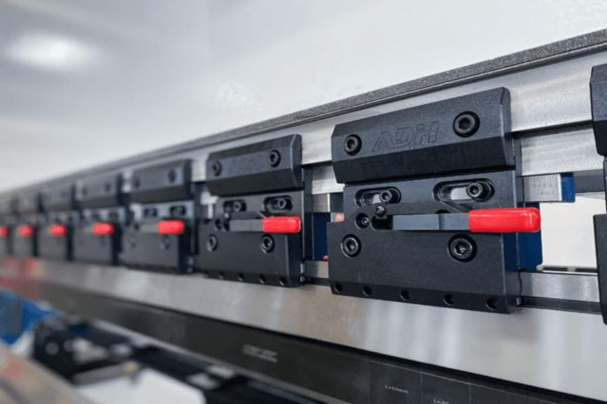
5.2 Die Clamping System: The Dual Pillars of Efficiency and Safety
The clamping system secures the dies firmly and precisely between the ram and the workbench. Its design evolution reflects the manufacturing industry’s relentless pursuit of efficiency, accuracy, and operator safety.
5.2.1 Evolution of Clamping Methods: From Manual Force to One-Touch Locking
(1) Manual Screw Fastening
The most traditional method. Operators must tighten each screw one by one with a wrench. The drawbacks are obvious—time-consuming, labor-intensive, inconsistent clamping force, and heavily reliant on the operator’s diligence—making it a bottleneck in modern production workflow.
(2) Hydraulic/Pneumatic Quick Clamping System
Now standard in modern CNC press brakes, this system allows operators to secure an entire row of dies by simply pressing a button. Hydraulic or pneumatic pistons integrated into the clamps extend instantly, exerting strong and uniform force. This is not just a technological improvement—it represents a fundamental shift in production philosophy.
5.2.2 ROI Analysis: How Much Setup Time Can a Quick-Clamping System Save?
Investing in a quick-change clamping system delivers returns far beyond its purchase price. The economics can be precisely calculated:
(1) Time Is Money
Replacing a full set of upper and lower dies manually can take an experienced operator 15 to 30 minutes. An advanced quick-change system reduces this to an astonishing 1–3 minutes. For small-batch, high-mix operations where multiple die changes occur daily, the accumulated time savings translate directly into increased productive hours.
(2) Improved Overall Equipment Effectiveness (OEE)
Reducing setup time minimizes machine downtime. Studies show that implementing quick-change technology can boost OEE by 5%–15%, meaning significantly higher output without adding machines or labor.
(3) Reduced Skill Dependency
Quick-clamping systems are simple to operate and ensure consistent clamping force. This eliminates variations caused by manual tightening, guarantees repeatable precision, and allows even less-experienced operators to handle die changes confidently.
5.2.3 Safety Mechanisms: Anti-Drop and Overload Protection
Efficiency gains should never come at the cost of safety. Modern clamping systems incorporate multiple fail-safe and protective design features.
(1) Anti-Drop Protection
Essential for segmented upper dies, this is literally a life-saving feature. Without protection, segments weighing tens of kilograms could fall when the system is released. Modern designs use safety pins or grooves, ensuring that even when unclamped, the die remains securely held—it can only slide out horizontally, never drop vertically.
(2) Overload Protection
This serves as the machine’s built-in self-preservation mechanism.
1)Relief Valve in the Hydraulic System:
When bending force exceeds the preset safety limit, the relief valve opens automatically to release pressure, effectively capping the system’s maximum tonnage. This prevents issues like mechanical lock-up caused by programming or operator errors, protecting the frame, cylinders, and dies from permanent damage.
2)Real-Time CNC Monitoring:
The CNC controller continuously monitors the applied pressure. If it detects any abnormal tonnage, it immediately halts operation and triggers an alarm, providing an additional layer of safety for the operator.
In summary, the die and clamping system at the machine’s end represent the intersection of precision, efficiency, and safety. A deep understanding of die selection and treatment is the foundation of process optimization, while investing in modern quick-clamping technology is a strategic move toward lean, agile manufacturing.
Ⅵ. FAQs
1. What is a press brake, and what is it used for?
A press brake is a machine tool used to bend sheet and plate material, typically metals, by clamping the workpiece between a punch and die. It is commonly employed in sheet metal fabrication industries to produce parts with specific angles and shapes, supporting applications such as forming channels, brackets, and structural components.
Press brakes are essential in industries like automotive, aerospace, and general manufacturing due to their precision, versatility, and capacity to handle a variety of metal thicknesses.
2. What are the primary components of a press brake?
Key components of a press brake include the frame, ram, bed, backgauge, punch, and die. The frame provides structural stability, while the ram moves vertically to press the punch onto the workpiece positioned over the die.
The backgauge assists in positioning the metal accurately for repeatable bending, and the control unit—manual, NC, or CNC—governs the operation and precision of the machine. Understanding these components and their roles is essential for effective press brake use and maintenance.
3. What are the differences between hydraulic, mechanical, and electric press brakes?
Common press brakes can be divided into hydraulic, mechanical, and electric press brakes. They differ in their operation and applications. Hydraulic press brakes are favored for their powerful force and flexibility, accommodating varying stroke lengths, which makes them suitable for thick and heavy materials.
Mechanical press brakes are precise and fast, driven by a flywheel but are generally limited to lighter tasks. Electric press brakes, known for energy efficiency and speed, offer high-precision control and are suitable for lighter or moderate applications where energy conservation and noise reduction are essential.
Each type has unique advantages, so understanding these differences helps in selecting the appropriate press brake for specific fabrication needs.