I. Overview of Shearing Machine
1. Shearing Machine Definition
A sheet metal shearing machine is a machine used in metal fabrication industry for cutting metal plates into various desired shapes and sizes.
The components of a shearing machine are blades, pulleys, baffles, and an electric control system. The machine's die, used to cut various materials, can be found in different shapes, commonly two blades: straight blades and round blades. For a more detailed understanding of how different blade types perform in hydraulic systems, you can also read the Guide to Hydraulic Shearing Machine Blades.
Shearing operations are widely used in various industries, such as automotive and aerospace manufacturing, machinery production, household appliance production, and construction.
The effectiveness of a sheet metal shearing machine is determined by several factors such as its shearing capacity, accuracy, speed, and reliability.
2. Key Technical Parameters of Shearing Machines
| Parameter | Description |
| Shearing Thickness | Maximum thickness of sheet metal that can be cut (typically 6-40mm) |
| Shearing Length | Effective length of the worktable, determining maximum width of sheet (typically 1-6m) |
| Shearing Angle | Angle between upper and lower blades (typically 1-3°; smaller for thin sheets, larger for thick) |
| Blade Clearance | Distance between lower and upper blades (8-12% of sheet thickness; affects burr formation and shearing force) |
| Shearing Speed | Speed of the shearing stroke (typically 8-20 strokes per minute; affects efficiency and vibration) |
| Holding Force | Force applied by hydraulic hold-down cylinders to clamp the sheet (e.g., 13 tons for 2500mm length) |
| Backgauge Stroke | Length of backgauge movement for precise positioning (e.g., 1000mm or more) |
| Backgauge Accuracy | Precision of backgauge positioning (e.g., ±0.2mm or better) |
| Blade Material | Typically high-carbon, high-chromium steel (e.g., HCHCr/D2) with hardness of 55 HRC or higher |
The term “rake” refers to the angular configuration of blades. Both rake and clearance are functions of the type and thickness of the material to be cut.
II. What Are the Types of Shearing Machines?
Depending on the drive mode, common types of shearing machines mainly include manual sheet metal shearing machines, mechanical shearing machines, hydraulic shearing machines, and pneumatic shearing machines.
1. Manual Sheet Metal Shearing Machine
Manual sheet metal shears are equipment that can perform cutting of plates by manually moving the blade up and down. These shears are powered by hand, easy to operate and suitable for cutting small plates, but their cutting accuracy is low and cannot meet the requirements of large plates.
2. Mechanical Shearing Machines
The mechanical shearing machine operates using a power device consisting of a motor, flywheel, worm shaft, and clutch. It has faster cutting speeds and more strokes per minute compared to the hydraulic shearing machine.
The flywheel of the mechanical shearing machine stores energy, allowing a motor with lower horsepower to be used. Based on the operation mode, mechanical shearing machines can be further divided into up-moving and down-moving types. To better understand the operational differences between these models and hydraulic types, explore this detailed guide on Hydraulic vs Mechanical Shearing Machines.
3. Hydraulic Shearing Machines
The hydraulic shearing machine is powered by a hydraulic cylinder and motor. The motor drives the hydraulic cylinder, applying hydraulic oil pressure to the piston, providing power to the upper blade's piston.
The hydraulic shearing machine has a longer stroke and can handle different load capacities. Materials cut using a hydraulic shearing machine have a smooth surface with minimal markings. These machines are known for their large shearing force, stable operation, and good controllability.
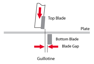
The hydraulic shearing machine can be categorized into two types: the swing beam shearing machine and the guillotine shearing machine.
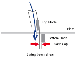
The swing beam shearing machine performs the shearing movement by swinging the tool rest, resulting in high speed, high shearing accuracy, and high efficiency.
The guillotine shearing machine can be powered either by hydraulic or mechanical means. It consists of a working table, upper and lower blades, a hydraulic piston, a clamping tool, and a blank holder.
This machine can cut plates of varying thicknesses and lengths due to their ability. The movable blade of the guillotine shearing machine can be straight or angled to reduce the cutting force.
Equipped with CNC system, the guillotine shearing machine can handle large cutting thicknesses and lengths with fast cutting speed, making it ideal for mass production. However, the cut edges produced are rough and unattractive.
Comparison of Mechanical and Hydraulic Shearing Machines
| Feature | Mechanical Shearing | Hydraulic Shearing |
| Transmission | Mechanical (crank linkage, gear) | Hydraulic (hydraulic cylinders) |
| Cutting Speed | Faster in full-cycle mode | Slower, but can operate continuously |
| Capacity | Limited to thinner materials (up to 1/4" plate) | Can cut thicker materials (3/8" to 1" plate) |
| Precision | Lower accuracy and adjustability | Higher accuracy and precise adjustments |
| Noise | Loud during operation, but quieter overall | Constant noise from hydraulic system |
| Maintenance | Simpler mechanisms, easier to maintain | More complex, but designed for easy operation and maintenance |
| Safety | Can be stopped mid-cycle, but more hazards | Automatic reverse, light curtains, overload protection |
| Cooling | Not required | Hydraulics run hot and require cooling |
| Environmental Impact | No hydraulic waste (oil, filters) | Produces hydraulic waste |
| Shock Resistance | More shock resistant due to robust construction | Less shock resistant due to hydraulic cylinders |
4. Pneumatic Shearing Machines
The pneumatic shearing machine refers to the equipment that uses a pneumatic system to control the up-and-down movement of the blade for plate cutting.
The pneumatic plate shearing machine offers high shearing speed and accuracy, as its blade movement can be adjusted through air pressure. It is commonly used for cutting special plates, such as those with high hardness and strength.
Thanks to its high cutting speed and accuracy, the pneumatic shearing machine is ideal for high-speed and high-precision cutting.
There are two main types of shearing machines for cutting plates: linear and circular. The linear shearing machine is powered by hydraulic devices and can handle thicker metal plates.
The circular plate shearing machine is powered by a motor and can cut circular metal plates. Each type of shearing machine has its own advantages and is suitable for different cutting needs.
Users can select the most suitable type of shearing machine based on their needs and the properties of the material.
For instance, manual shearing machines are ideal for cutting small plates, while large plates may require a guillotine shearing machine or a pneumatic shearing machine.
III. What Are the Main Components of the Shearing Machine?
The main components of shear equipment are the working table, upper and lower shearing blades, clamping tools, baffles, and electrical elements.
The blades, typically made from high-strength steel with good hardness and wear resistance, are the primary working component of the machine.
They can be moved up and down to perform the cutting of the sheet metal. The clamp is used to secure the metal sheet in place for accurate cutting.
The baffle serves as a protective measure for the plate shearing machine. Made from high-strength metal materials, it guards against external forces impacting the plate. The baffle is typically installed near the blade edge of the machine for maximum safety of the workers.
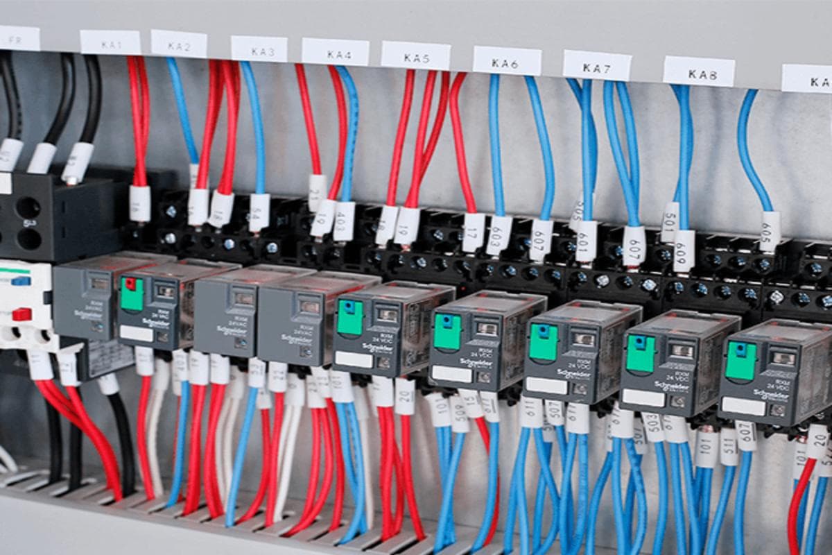
The electrical elements control the operation of the shearing machine and consist of a circuit board, motor, and controller. These elements monitor and control the machine's running state to ensure safe operation.
IV. What Is the Working Principle of the Shearing Machine?
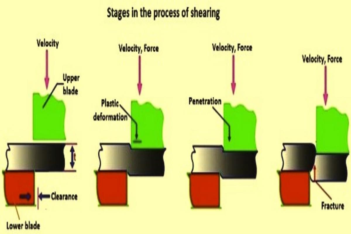
1. Breaking Down the Physics: From Force Application to Fracture in Three Stages
The metal shearing process can be broken down into three closely interconnected stages, which form the basis for professionals to assess the quality of the cut:
(1) Elastic and Plastic Deformation
When the upper blade first contacts the sheet, the material undergoes elastic deformation, meaning it fully returns to its original shape upon unloading. As stress continues to rise and surpasses the material’s yield point, the metal enters a stage of plastic deformation. At this point, the sheet’s edge is forced into the blade gap, resulting in permanent deformation and setting the stage for the cut to occur.
(2) Penetration and Microcrack Formation
As the blade penetrates deeper into the material, the intense concentration of pressure at its tip drives local stress beyond the shear strength threshold. This is when microcracks begin to form near the leading and trailing edges of the blades. This phase is critical in determining how much of the cut surface will be smooth and shiny. Blade sharpness and gap settings directly impact crack propagation and uniformity.
(3) Fracture and Separation
Cracks generated by the upper and lower blades rapidly expand along the designated shear line and meet, producing a complete cut surface. An optimal shear face should display a balanced ratio between the smooth zone and the fracture zone, typically around 1:2. This indicates that machine settings are well-matched to the material’s properties, yielding a clean edge with minimal burrs.
2. Core Component Anatomy: How the Five Main Systems Work in Harmony
A high-quality shear machine is the result of five key systems working seamlessly together:
(1) Frame and Worktable
A fully steel-welded or cast frame provides high rigidity, and its resistance to deformation directly affects long-term accuracy. The flatness of the worktable plays a crucial role in ensuring stable sheet positioning.
(2) Blade System
Comprising upper and lower blades along with their mounting assemblies, these are often made from high-carbon, high-chromium tool steel. They must offer both hardness and toughness to prevent brittleness and cracking. A well-designed blade geometry helps reduce energy consumption.
(3) Power System
Hydraulic models use cylinders for adjustable, steady force, while mechanical models rely on crankshafts and flywheels to deliver fixed power at high speeds, making them ideal for standardized thin-sheet production.
(4) Backgauge Positioning
This can be manual, semi-automatic, or fully CNC-driven, and directly affects dimensional consistency. CNC backgauge systems can repeat positioning multiple times without deviation.
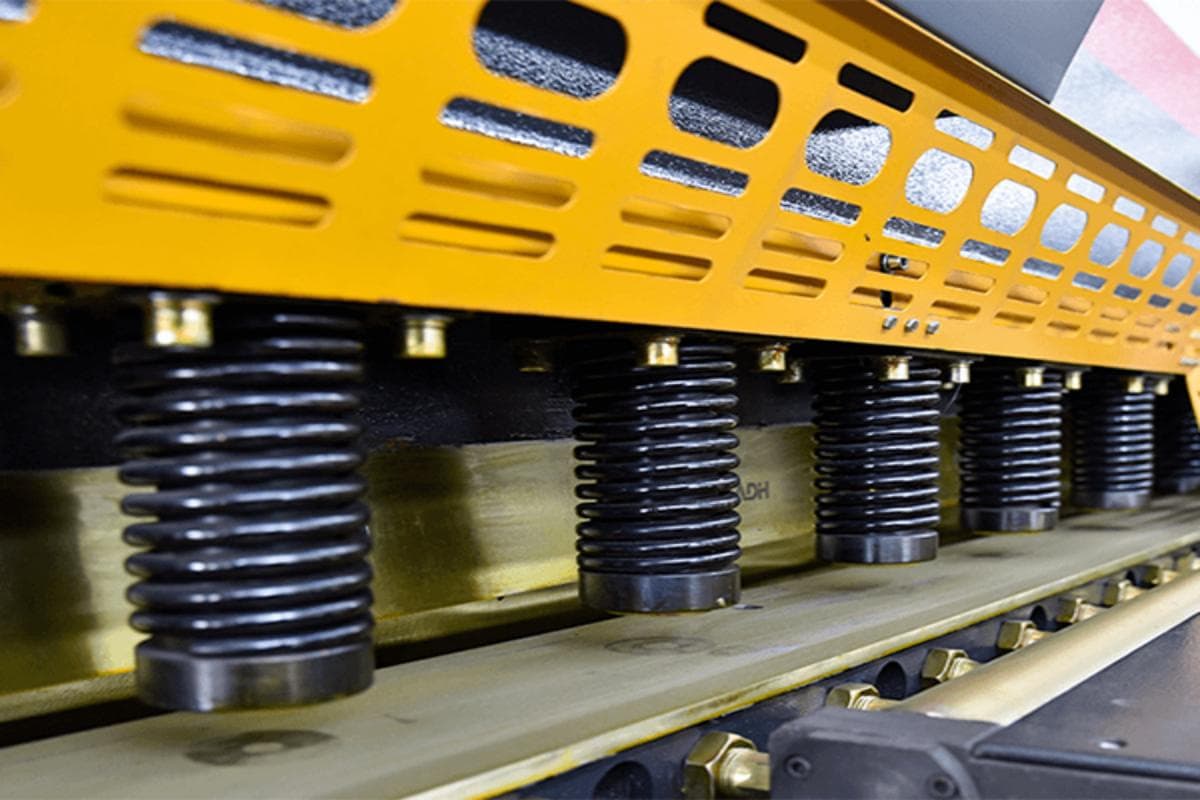
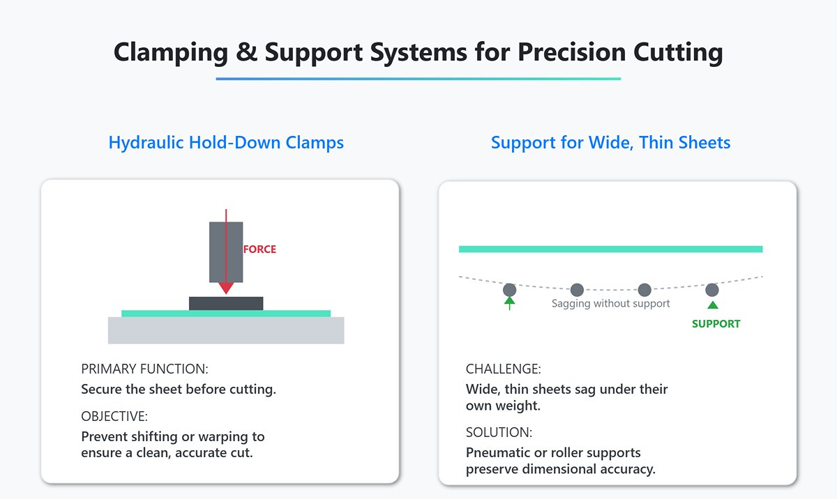
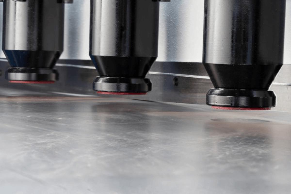
(5) Clamping and Support
Hydraulic hold-down clamps secure the sheet before cutting to prevent shifting or warping. For wide, thin sheets, pneumatic or roller supports are used to counteract sagging from the sheet’s own weight, preserving dimensional accuracy.
3. The Quality Control Trifecta: The Golden Rules of Shear Angle, Blade Gap, and Speed
Three core variables collectively determine shearing performance:
(1) Shear Angle
A larger shear angle reduces instantaneous load but may cause twisting in narrow strips. A smaller angle yields smoother cuts but requires higher tonnage and stronger support. The choice is usually a trade-off based on sheet thickness and hardness.
(2) Blade Gap
The recommended setting is 5%–10% of sheet thickness to ensure a smooth surface with minimal burrs. Too large a gap causes tearing, while too small a gap increases wear and may result in a "double-cut" defect.
(3) Shearing Speed
High speeds boost productivity and suit ductile materials like low-carbon steel. Lower speeds give better control over cut quality and are preferable for hard or brittle materials. Hydraulic machines can finely adjust speed to suit the task.
Poor parameter combinations can lead to higher scrap rates, reduced blade lifespan, and even damage to the frame or drive system.
(4) Typical Blade Gap Reference Values (percentage of sheet thickness):
- Aluminum and soft alloys: 3%–5%
- Low-carbon steel: 5%–8%
- Stainless steel: 7%–10%
- High-strength steel: 10%–14%
Optimal values should be fine-tuned according to specific material grades and tested on-site.

V. Features of the Shearing Machine
The shearing machine precisely cuts metal plates to the desired size through a moving blade that moves up and down. The speed of the blade can be controlled via electrical elements, ensuring accurate cuts.
This machine is capable of cutting a wide range of materials, including stainless steel, aluminium, copper, and other types of plates. It is user-friendly and safe, requiring only a basic understanding of its operation for successful use.
The shearing machine also has safety features that protect both the plates and workers from external forces.
VI. What Is the Shearing Machine Mainly Used for?
The shearing machine provides efficient support for industrial production with its high-precision and high-speed cutting capabilities.
These machines are specialized tools used in industries such as machinery manufacturing, aerospace, and automobile manufacturing.
In the aerospace industry, for instance, the shearing machinery can be utilized to cut high-strength steel plates to produce aircraft parts.
The machine can also be utilized in the production of automobile components, such as bodies and doors, by cutting both steel and aluminum plates.
In addition to industrial applications, shearing machines are also used in various other fields, including household appliances, electronics, and building decoration.
For example, in the household appliance industry, the shearing machine is used to cut stainless steel plates for products such as refrigerators and air conditioners.
In the electronics industry, it can be used to cut aluminium plates for the production of computer and mobile phone shells.
VII. What Are the Blade Materials of the Shearing Machine?
The blades of the shearing machine are mainly composed of high-speed steel, carbon steel, and other materials. High-speed steel is a commonly used blade material that is characterized by its high wear resistance and rigidity.
Thanks to its high stiffness, high-speed steel blades can significantly enhance the cutting efficiency of the shearing machine.
After undergoing fine processing, they can also improve the machine's shearing accuracy. Carbon steel, on the other hand, is an economical blade material with high toughness.
The high toughness of carbon steel blades makes them resistant to vibrations and deformations during shearing. Additionally, after undergoing heat treatment, they can also improve the shearing accuracy of the machine.
In conclusion, the blade materials of the shearing machine can include high-speed steel, hard alloy, carbon steel, and others. The choice of blade material depends on the specific working conditions and budget of the machine.
Ⅷ. Practical Methods: A Complete Operational Guide from Start-up to Maintenance
Theory provides the blueprint, but meticulous hands-on execution is the only way to transform that blueprint into a flawlessly finished product. In this chapter, we move beyond abstract principles to offer a fully standardized, workshop-proven SOP you can immediately implement. This is not just a set of operating instructions — it’s a professional code of practice designed to ensure safety, enhance quality, and extend the lifespan of your equipment. From the pre-start inspection, through every motion during cutting, to daily care and maintenance, each step is critically important.
1. Preparation Phase: Safety and Calibration Checklist to Eliminate Risks
Every time you start the shearing machine, treat it as a pledge to uphold both safety and precision. The checklist below is your “pre-flight” procedure to prevent accidents and guarantee first-cut accuracy — it must be followed without exception.
(1) Safety Check (Safety First)
1)Protective Devices:
Ensure all physical guards and safety doors are closed and securely locked.
2)Emergency Stop System:
Test every emergency stop button — including those on foot switches — to confirm proper function and fast response.
3)Light Curtain Protection:
If equipped, use an object to block the optical guard to verify it immediately halts the shearing action.
4)Lockout/Tagout (LOTO):
Before any blade adjustment, repair, or cleaning, rigorously follow the “power off – lock – tag” procedure. This safety boundary is non-negotiable.
(2) Machine Calibration (Precision Foundation):
1)Blade Gap:
This is the essential daily adjustment. Set precisely for the day’s material type and thickness, either manually or via CNC.
2)Golden Rule:
For low-carbon steel, set gap to about 7–10% of sheet thickness; stainless steel, 5–7%; aluminum, 4–6%.
3)Verification:
After adjusting, use a feeler gauge to measure left, center, and right blade positions. Consistency is vital; uneven gaps cause twist, poor cuts, and excessive blade wear.
4)Back Gauge:
Initialize the CNC system by returning to the reference or zero point to ensure absolute positioning accuracy. Measure actual back gauge position with calibrated tools (e.g., digital calipers) and correct any discrepancies.

(3) Material & Workspace Readiness (Clean Workspace)
1)Material Inspection:
Remove oil, scale, weld spatter, or contaminants from sheet surfaces. Level warped sheets beforehand, as uneven stock compromises cut quality and safety.
2)Worktable Cleaning:
Clear the table surface of debris and obstructions to prevent scratches and ensure perfect contact with alignment references.
2. Step-by-Step Guide: Achieving a Perfect Single Cut
Following these five standardized steps is key to achieving high-speed, high-accuracy cuts.
(1) Step 1: Parameter Setup
On the control panel, enter precise shearing parameters: cut length (back gauge position), number of cuts, and mode (single/continuous). For CNC systems, you may also select material type and thickness from the database, prompting the system to suggest optimal cutting angle and blade gap.
(2) Step 2: Material Alignment
Place the sheet smoothly on the worktable. Press one straight base edge firmly — with no gap — against the side block or locating arm. This ensures the finished workpiece is a true rectangle, not skewed.
(3) Step 3: Precise Positioning
Push the sheet toward the machine’s rear until its edge contacts the back gauge evenly across its length. Ensure the sheet lies flat without lifting or warping, keeping the base edge aligned with the side block throughout.
(4) Step 4: Execute the Cut
Press the foot pedal or start button. Confirm that the hold-down cylinders engage before the upper blade descends, securing the sheet firmly. This step prevents sheet movement and safeguards dimensional accuracy. Once the cut is complete and the upper blade returns fully to its top position, remove the workpiece.
(5) Step 5: Quality Inspection (First-Piece Check)
Examine the first piece cut with precision measuring tools to verify length and diagonal for size tolerance and squareness. Inspect the cut edge:
(6) Burrs
Check by touch (with care) or visually — burrs should be minimal and uniform. Excessive burrs usually indicate incorrect blade gap or worn edges.
(7) Cut Surface Characteristics
An ideal cut shows about one-third burnished zone (clean blade cut) and two-thirds fractured zone. This ratio is a practical indicator of proper blade gap.
3. Blade Management Essentials: Maximizing Lifespan and Reducing Costs
Blades are the core consumable of a shearing machine. Smart management can extend their life several times over, directly boosting profit margins.
(1) Wear Detection: Learn to "listen" and "look."
1)Listen:
The shearing sound changes from sharp to dull and labored.
2)Look:
Notable burr increase, tiny ledges from secondary shearing on the cut edge, amplified sheet distortion. If blade gap adjustment no longer improves results, it’s time to regrind or rotate blades.
3)Rotation Strategy:
Most shear blades (especially guillotine type) have four usable edges. Rather than regrounding immediately after wear, remove and rotate the blade 90° to expose a fresh edge. A strict rotation plan ensures even use of all four edges, maximizing blade value.

(2) Proper Grinding & Replacement
1)Grinding:
Only trained professionals using dedicated blade grinders should regrind blades, ensuring true straightness and correct edge angles. Poor grinding can permanently damage blades.
2)Replacement:
After installing new blades, always recalibrate blade gap and parallelism between upper and lower blades to restore original machine precision.
4. Common Defect Troubleshooting: Quick Reference Problem-Cause-Solution
A practical diagnostic guide to help you quickly identify issues and apply effective solutions.
(1) Issue: Excessive burr on cut edge
1)Possible Causes:
① Excessive clearance between blades.
② Severe blade wear or chipping.
2)Solutions:
① Reset the clearance to the recommended value according to the material’s thickness and type.
② Switch to a fresh cutting edge or send blades for sharpening/replacement.
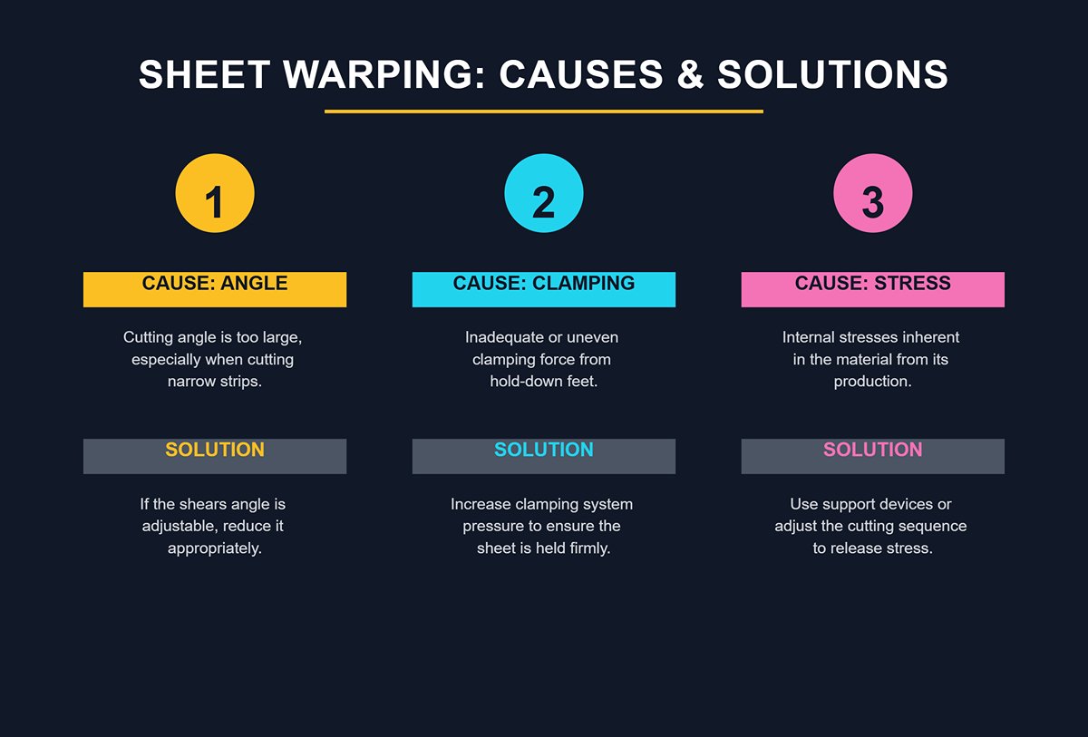
(2) Issue: Sheet warping or bowing
1)Possible Causes:
① Cutting angle too large (common when narrow strips are cut on a swing beam shear).
② Inadequate clamping force or uneven distribution among hold-down feet.
③ Internal stresses inherent in the material.
2)Solutions:
① If the cutting angle is adjustable, reduce it appropriately.
② Increase clamping system pressure to ensure all hold-down feet firmly secure the sheet.
③ Use front and rear support devices for thin sheets, or adjust cutting sequence to release internal stresses.
(3) Issue: Inconsistent dimensional accuracy
1)Possible Causes:
① Loose or worn back-gauge drive system (e.g., ball screw).
② Sheet not fully flush with the back gauge during positioning.
③ Insufficient clamping force causes sheet movement during cutting.
2)Solutions:
① Inspect and tighten all back-gauge connections, and recalibrate positioning accuracy.
② Enforce proper setup, ensuring each positioning is firm and precise.
③ Increase clamping force.
(3) Issue: Stepped surface from “secondary shearing”
1)Possible Cause:
Blade clearance set too narrowly, causing the material to be excessively compressed and torn before separation.
2)Solution:
Increase blade clearance appropriately and recheck the first piece’s cut surface until it returns to the standard profile of “one-third bright band + two-thirds fracture band.”
VIII. Future Development Trends of the Shearing Machine
The future direction of the shearing machine's development may be impacted by various factors, including economic growth, market demand, and technological advancements.
With the rise of intelligent technology, the shearing machine is expected to become more advanced, featuring additional intelligent functions such as automatic blade position adjustment and automatic plate type and thickness identification.
The implementation of digital technology can lead to more efficient production management and quality control, making the shearing machine even more efficient.
In addition, the integration of the shearing machine with other equipment is expected to improve production efficiency and quality by achieving seamless connections.
Finally, the shearing machine will strive to reduce its environmental impact by reducing energy consumption and the emission of pollutants.
IX. Maintenance of Shearing Machine
1. Daily Maintenance
Before each start-up, add lubricating oil on time, at fixed points, and in fixed quantities according to the lubrication chart. The oil should be clean without sediment. The machine must be kept clean frequently, and rust-proof grease should be applied to unpainted parts.
10 minutes before getting off work every day, lubricate and clean the machine. Clean the machine every week, and add lubricating oil to each guide surface, sliding surface, ball, and lead screw.
2. Regular Inspection
Regularly check the straightness and axial clearance of the lead screw. If it exceeds the tolerance or is too large, replace or adjust it in time. Regularly check whether the V-belt, handle, knob, and buttons are damaged. Those with severe wear should be replaced in time.
Regularly inspect and repair switches, fuses, and handles to ensure their reliable operation. The lubricating oil in the motor bearing should be replaced regularly, and check whether the electrical parts work normally.
3. Blade Maintenance
Regularly check the wear of the blades. Dull blades should be sharpened or replaced in time. Stop the machine first when replacing the blade, and ensure that the new blade is installed securely.
4. Other Key Points
Strictly follow the operating procedures and eliminate illegal operations. Keep the working environment clean and clean up the cutting waste in time. Turn off the power when leaving the machine for a long time to prevent non-professionals from operating.
If there is any abnormality during operation, press the emergency stop button immediately and troubleshoot the cause of the fault.
X. Conclusion
This article provides an overview of the main types, components, working principles, features, applications, and blade materials of shearing machines. Plate shearing machines are widely used in the manufacturing industry and are a highly versatile piece of equipment.
When choosing a shearing machine manufacturer, it is important to consider its common shearing machine prices, functions, warranty, and other factors in detail.
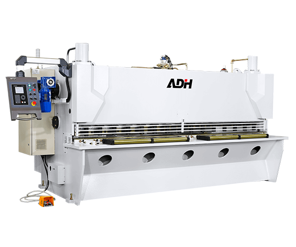
ADH is a reputable sheet metal processing machine manufacturer with 20 years of experience. The quality and performance of their press brake, plate shearing machine, laser cutting machine, and other machines are guaranteed.
You can find detailed specifications for all our equipment by viewing our brochures. For any further questions or to request a quote, please do not hesitate to contact us.


