I. Introduction to Laser Cutting Machine Tolerance
Laser cutting has revolutionized the manufacturing industry by enabling high-precision cutting of various materials. However, achieving and maintaining precise cuts necessitates a thorough understanding of tolerance, a critical parameter in laser cutting operations.
To further understand advanced cutting methods and how tolerance affects angled precision, you can refer to the Complete Guide to Angled Laser Cutting.
1. Definition of Laser Cutting Machine Tolerance
Tolerance in laser cutting refers to the allowable deviation from a specified dimension. This deviation can be either positive or negative and is an indication of the machine's precision and accuracy in producing parts.
Tolerance defines the acceptable limits of variation in the dimensions and geometry of a cut piece, ensuring it fits the purpose for which it is designed.
2. Importance of Tolerance in Manufacturing
Tolerance is paramount in manufacturing as it directly affects product quality and fitment. Precise tolerance levels ensure that components fit together correctly, operate efficiently, and meet stringent quality standards.
Inconsistent or poor tolerance can lead to parts that do not assemble properly, cause redundant wear and tear, and fail to meet the safety and performance requirements, significantly impacting the overall functionality of the product.
3. Tolerance Ranges for Industrial Laser Cutting Machines
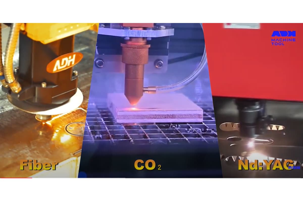
Industrial laser cutting machines, often classified based on their laser source, such as CO2, fiber, or YAG lasers, can achieve different levels of tolerance. Typically, high-end laser cutting machines can maintain tolerances as tight as ±0.1 mm, depending on factors like material type, thickness, and machine settings.
Understanding the specific tolerance range of each machine type is crucial for selecting the right equipment for particular manufacturing needs.
4. Impact of Tolerance on Quality and Precision
The impact of tolerance on quality and precision is profound. Tight tolerances are indicative of superior machine capability and lead to high-precision cuts that align perfectly with design specifications.
This precision is integral to industries such as aerospace, automotive, and medical devices, where even minor deviations can lead to significant operational issues or safety hazards.
Furthermore, consistent tolerance levels contribute to minimizing material wastage, improving production efficiency, and reducing costs associated with rework and scrap.
II. Tolerance Levels of Different Laser Cutting Machines
Before diving into the complex variables that affect achievable tolerances, it’s essential to grasp a fundamental truth: not all lasers are created equal. The type of laser technology you choose establishes the baseline precision capabilities of your product from the very origin of its physical principles. Think of it like selecting a mode of transportation—bicycles and supersonic jets operate within vastly different speed limits. In this section, we’ll dissect four mainstream laser technologies in detail, exposing the inherent differences in their “tolerance DNA” so you can make the smartest technical choice right from project inception.
1. CO₂ Lasers: The sweet spot between versatility and cost efficiency (Typical tolerance: ±0.1mm to ±0.5mm)
A true veteran of industrial processing, CO₂ lasers have been in service for over half a century. By energizing a gas mixture of carbon dioxide and other elements, they generate long-wave infrared light at 10.6 μm. This tried-and-tested technology has earned its place as the first laser cutting device for countless factories due to its maturity and reliability.
(1) Capability Boundaries and Physical Limits
Under optimal conditions, a well-maintained, high-grade CO₂ laser can consistently achieve tolerances of ±0.1mm. However, its relatively long wavelength means the beam can’t be focused to the ultra-fine spot size possible with fiber lasers, and its cutting process relies more on thermal melting. When working with thicker materials (e.g., over 12mm) or targeting high-speed cuts, the heat-affected zone (HAZ) widens, taper becomes more pronounced, and tolerances typically widen to ±0.25mm–±0.5mm.
Core Advantages
1)Outstanding material versatility:
The wavelength of CO₂ lasers is efficiently absorbed by most non-metal materials—acrylic, wood, leather, textiles—making it irreplaceable in these domains. Here, it remains a top performer in cut quality and cost-effectiveness.
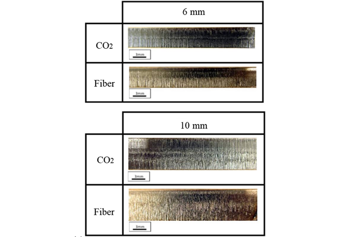
2)Superior thick plate edge quality:
When cutting thick carbon steel plates (e.g., over 20mm), CO₂ lasers often deliver smoother, brighter, burr-free, mirror-like cut edges—critical for certain demanding structural applications.
Hidden Challenges:
1)Poor performance with highly reflective metals:
Brass, pure copper, and aluminum can reflect most of a CO₂ laser’s energy like a mirror, severely reducing efficiency. Worse, reflected beams can damage costly optical components.
2)Non-negligible operating costs:
The complex gas resonator, turbines, and mirrors in the beam path require regular maintenance, calibration, and occasional replacement—driving up long-term operational expenses.
2. Fiber Lasers: The speed and precision champion for thin-to-medium metal cutting (Typical tolerance: ±0.05mm to ±0.2mm)
Over the past decade, fiber lasers have revolutionized the metalworking industry. Pumped by semiconductor diodes and transmitted through optical fiber, they produce light at around 1.06 μm—an order of magnitude shorter in wavelength than CO₂ lasers.
(1) Capability Boundaries and Physical Limits
The shorter wavelength and exceptional beam quality (M² approaching 1) allow fiber lasers to be focused to spots just tens of microns in diameter, yielding extremely high energy density. This leads to narrower kerf widths and minimal heat-affected zones. As a result, fiber lasers can stably achieve ±0.05mm tolerances, and in precision sheet metal work, ±0.025mm is readily attainable.

(2) Core Advantages
1)Dominant speed and efficiency:
When cutting metal sheets under 10mm thick, fiber lasers can be 2–4 times faster than CO₂ lasers of the same power. With electrical-to-optical efficiency above 30% (vs. ~10% for CO₂), they deliver substantial energy savings.
2)Highly reflective material specialist:
Their shorter wavelength is readily absorbed by copper, brass, and other highly reflective metals, eliminating one of CO₂ lasers’ main limitations and enabling fast, high-quality production on these materials.
3)Near-zero maintenance reliability:
Solid-state fiber transmission means no internal mirrors to align or gases to replenish, resulting in excellent stability and very low ongoing costs.
(3) Hidden Challenges
1)Thick plate cut quality limits:
Although modern high-power (12kW+) fiber lasers have strong thick plate capabilities, when cutting extremely thick carbon steel (e.g., >30mm), edge verticality and surface smoothness may still be marginally inferior to top-tier CO₂ lasers.
2)Higher upfront investment:
Fiber laser cutters of equivalent power generally carry higher purchase prices than CO₂ models, though their efficiency and low running costs often recover the price gap within 1–2 years.
3. Advanced Laser Technologies (Nd:YAG/Disc): Meeting the toughest demands for specialty materials (Typical tolerance: ±0.025mm to ±0.15mm)
Nd:YAG (neodymium-doped yttrium aluminum garnet) and disc lasers are both solid-state systems with wavelengths similar to fiber lasers. In certain applications, they offer distinctive, irreplaceable advantages.
(1) Capability Boundaries and Physical Limits
Renowned for extremely high peak power and flexible pulse control, these systems can carry out precise 'impact-style' machining without generating excessive heat. They excel in tolerance capability—especially in microfabrication—achieving consistent ±0.025mm or better.
(2) Core Advantages
1)Unmatched peak power: Nd:
YAG lasers can deliver ultra-high energy short pulses, making them ideal for metal micro-drilling, precision spot welding, and deep engraving. They are the standard choice for specialized tasks like cooling hole fabrication in aerospace turbine blades.
2)Balanced performance of disc lasers:
Disc laser design blends CO₂-like beam quality with solid-state efficiency, performing equally well in thick plate cutting and processing reflective materials—earning it a reputation as a versatile all-rounder.
3)Application Scenarios:
Given their specific advantages and higher costs, these lasers are typically deployed in cutting-edge sectors requiring strict control over heat input and peak power, such as medical device manufacturing, precision mold repair, and deep marking of automotive components.
4. Ultra-Precision Laser Technologies (UV/Femtosecond): The pinnacle of microfabrication accuracy (Typical tolerance: ±0.005mm to ±0.025mm)
When tolerance demands shift from the hundredths of a millimeter range into the single-micron domain, traditional thermal cutting methods reach their limits. Here, ultra-precision laser technologies based on 'cold processing' principles take center stage.
(1) Capability Boundaries and Physical Limits:
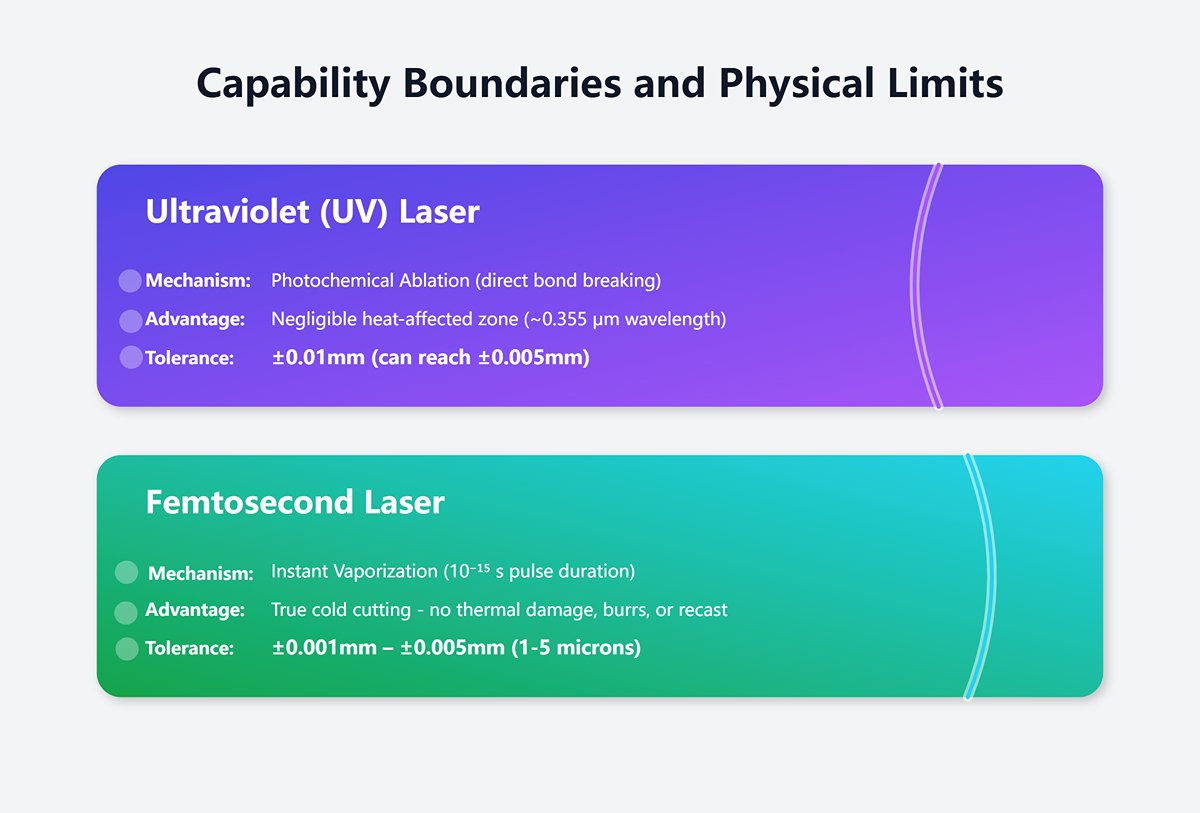
1)Ultraviolet (UV) lasers:
With extremely short wavelengths (~0.355 μm), UV photons carry enough energy to break molecular bonds directly rather than melt the material. This 'photochemical ablation' process produces a negligible heat-affected zone. Tolerances of ±0.01mm are easily achieved, and in certain applications, precision can reach ±0.005mm.
2)Femtosecond Laser:
With pulse durations as short as one quadrillionth of a second (10⁻¹⁵ s), energy is delivered with extreme precision, instantly vaporizing material before heat can spread to the surrounding area. This enables true cold cutting—free from thermal damage, burrs, or recast layers—resulting in flawless edges. Achievable tolerances consistently fall within the 1–5 micron range (±0.001mm – ±0.005mm).
(2) Core Applications:
1)UV Laser:
Extensively used for cutting flexible printed circuits (FPC), ceramic thin sheets, glass, and heat-sensitive medical polymers.
2)Femtosecond Laser:
Applied in manufacturing medical implants such as heart stents, dicing semiconductor wafers, precision drilling of aircraft engine fuel nozzles, and machining ultra-hard, brittle materials like diamond and sapphire.
3)Cost Considerations:
These technologies have the highest equipment and operating costs among all laser systems. They serve as ultimate solutions for critical microfabrication challenges, rather than for routine mass production.
2.5 [Decision Tool] Key Performance Comparison Matrix: A One-Glance Guide to Technology Selection
To help you efficiently pinpoint the most suitable technology from a range of complex options, the table below offers a straightforward side-by-side comparison of four major laser systems across multiple performance dimensions. Treat it as your navigation map for technology selection.
| Feature / Technology | CO₂ Laser | Fiber Laser | Nd:YAG / Disk Laser | UV / Femtosecond Laser |
|---|---|---|---|---|
| Typical Tolerance | ±0.1mm to ±0.5mm | ±0.05mm to ±0.2mm | ±0.025mm to ±0.15mm | ±0.005mm to ±0.025mm |
| Core Strength | Highly versatile across materials; superior thick-plate cutting quality | Exceptional metal cutting speed and efficiency; maintenance-free | Very high peak power, suitable for drilling and specialty welding | “Cold processing” with no thermal damage; ultimate precision |
| Best Material Applications | Non-metals (acrylic, wood), thick carbon steel | Thin to medium metal plates (steel, aluminum, copper, brass) | High-reflectivity metals, specialty alloys, ceramics | Polymers, glass, ceramics, semiconductors, biomaterials |
| Cutting Speed | Slow (especially on metals) | Fastest (<12mm metal) | Moderate | Slow (precision-focused) |
| Initial Investment Cost | Medium ($) | High ($$) | High to very high ($$ – $$$) | Extremely high ($$$) |
| Hourly Operating Cost | Medium (gas, electricity, maintenance) | Low (energy-efficient, maintenance-free) | Medium to high (pump source lifespan) | High (light source lifespan, complex maintenance) |
| Main Limitations | Cannot efficiently process high-reflectivity metals | Edge quality issues on ultra-thick plates | Poor cost-effectiveness for general cutting | Slow macro-scale processing; extremely high cost |
III. Factors Affecting Laser Cutting Machine Tolerance
Achieving optimal tolerances is never the result of a single factor—it’s the outcome of four pillars working in synergy: the machine’s inherent hardware "genes," how the material responds to the laser, the operator’s fine-tuning of process parameters, and the invisible environmental influences on production. Mastering and controlling these four dimensions is the only way to truly move from ±0.1mm to ±0.005mm precision.
1. Pillar One: Equipment Genes – The Hardware Precision Ceiling of the Machine
The machine’s factory configuration fundamentally determines its maximum achievable accuracy—much like an athlete’s innate physical abilities set the upper limits of their performance. No amount of software tuning or technique can surpass the physical boundaries defined by its hardware.
(1) Motion System: How Rack-and-Pinion, Ball Screws, and Linear Motors Define Positioning Precision
The motion system is the “skeletal and muscular” structure of the machine, responsible for moving the cutting head accurately along X, Y, and Z axes. Different drive mechanisms offer vastly different precision and cost profiles, directly shaping the machine’s accuracy class.
1)Rack-and-Pinion Drive:
The most cost-effective option, common in large-format, high-speed machines where tolerances are less critical (e.g., signage and decorative sectors). Its main advantage is accommodating long travel distances, but gear engagement inevitably introduces mechanical backlash. Frequent acceleration, deceleration, and reversals can lead to positioning errors. Typical positioning precision is around ±0.1mm, insufficient for high-accuracy assembly work.
2)Ball Screw Drive:
The mainstream choice for mid- to high-end laser cutters. Here, a servo motor rotates the screw, efficiently translating rotary motion into linear motion. Compared with rack-and-pinion systems, ball screws offer smoother transmission, greater rigidity, and—thanks to preloading—can eliminate most backlash. High-quality ball screw setups can achieve repeatable positioning precision of ±0.005mm, forming a solid foundation for precision machining.
3)Linear Motor Drive:
The pinnacle of precision, favored for ultra-accurate machining. Think of a linear motor as an “unrolled” servo motor, directly converting electrical energy into linear motion and removing all intermediate drive elements such as couplings or screws. Key advantages include:
4)Zero Transmission Error:
With no mechanical contact, there’s no wear, elasticity, or backlash, enabling positioning precision of ±0.001mm or better.
5)Ultra-High Dynamic Response:
Far greater acceleration and speed than ball screws, allowing superior performance in high-speed contour cutting and sharper corners due to faster responsiveness to control commands.
6)Direct Position Feedback:
Often paired with linear encoders such as optical scales, these systems measure the actual load position rather than the motor’s rotation angle, guaranteeing true accuracy—"what you measure is what you get."
(2) Mechanical Structure: The Crucial Role of Rigidity, Alignment, and Maintenance
Even a machine equipped with a top-tier linear motor cannot deliver high precision if its frame lacks structural rigidity.
1)Machine Rigidity:
Under high acceleration, a poorly rigid frame can deform or vibrate slightly, causing deviations in cutting paths. This is why premium precision machines typically use solid granite bases, cast structures, or heavy welded frames subjected to rigorous thermal treatments and aging processes—to absorb vibration and suppress deformation.
2)Calibration and Maintenance:
Precision requires upkeep. Regular laser path calibration, guide rail lubrication, lens cleaning, and geometric inspections (e.g., perpendicularity, straightness) of the motion system are vital to prevent accuracy loss over time. Neglected maintenance can cause noticeable precision declines within just six months.

(3) Optical System: The Fine-Scale Impact of Lens, Nozzle, and Focus Quality
The optical system is the laser’s final checkpoint before contacting the workpiece, directly determining cutting sharpness and consistency.
1)Lens Quality:
The cleanliness, material, and coating quality of the focusing lens are critical. Any contamination—such as metal dust or oil residue—can absorb laser energy, causing the lens to overheat and deform (known as the thermal lens effect). This leads to focal point drift and degradation of beam quality, ultimately impacting cutting precision and consistency.
2)Nozzle Design:
The nozzle is more than just an outlet for assist gas—it shapes and directs the flow. Its concentric alignment with the laser beam, along with its diameter and form, directly determine how efficiently and evenly molten material is expelled. A poorly designed or worn nozzle can disrupt airflow, resulting in dross buildup, rough cut surfaces, and dimensional inaccuracies.
3)Focal Quality (Spot Size):
A smaller spot produces higher energy density and finer kerfs (Kerf width). Spot size is defined by both the laser source’s beam quality and the focal length of the lens. Shorter focal lengths yield smaller spots for precision cutting but reduce depth of focus, making material flatness more critical.
2. Pillar Two: Material Properties – How the Workpiece “Responds” to the Laser Beam
Different materials react in vastly different ways to the same laser beam. Treating the material as a passive recipient is a serious misconception—the physical and chemical characteristics of the material actively influence every stage of the cutting process.
(1) Material Types and Grades: Tolerance Differences Between Metals and Non-Metals
1)Metals:
Tolerance control for metallic materials is generally well-established. Common metals such as stainless steel, carbon steel, and aluminum, thanks to their uniformity, deliver stable, predictable results when processed with correct parameters. However, highly reflective metals like brass or copper absorb fiber laser energy less efficiently, requiring higher power or specialized techniques, and posing greater challenges for thermal management during the process.
2)Non-Metals:
Plastics, wood, and composites pose greater challenges. For example, acrylic tends to melt during cutting, requiring precise energy control to achieve a smooth, flame-polished edge. Natural materials like wood have inconsistent density and internal knots, which lead to uneven cutting. Overall, non-metal tolerance ranges tend to be wider than those of metals.
(2) Thickness Effect: Why Greater Material Thickness Makes Tolerance Control More Difficult
Material thickness is one of the most significant factors affecting tolerance accuracy. The thicker the material, the harder it becomes to maintain tight tolerances—difficulty increases exponentially. The underlying physical reasons include:
1)Higher Energy Requirement:
Cutting thick plate demands greater laser power and slower speeds, resulting in more heat delivered into the material.
2)More Difficult Dross Removal:
Assist gas must expel molten material from deeper kerfs, which is harder, increasing the risk of bottom dross or incomplete cuts.
3)Expanded Heat-Affected Zone:
Increased heat input enlarges the HAZ, exacerbating thermal distortion.
4)More Pronounced Taper:
A laser beam, with its Gaussian profile, is inherently conical rather than perfectly parallel. In thick plate, this produces a mismatch between top and bottom kerf widths, creating taper.
Illustrative Relationship Between Typical Tolerance and Material Thickness (Stainless Steel Example)
| Material Thickness | Typical Tolerance Range | Main Challenges |
|---|---|---|
| < 1mm | ±0.05mm | Thermal distortion, warping |
| 1mm - 6mm | ±0.1mm | Balancing speed with quality |
| 6mm - 12mm | ±0.15mm – ±0.2mm | Taper control, bottom dross removal |
| > 12mm | ±0.25mm or wider | Perpendicularity, dross removal, cutting stability |
(3) Thermal Properties: Heat-Affected Zone (HAZ), Material Stress, and Managing Thermal Deformation
1)Heat-Affected Zone (HAZ):
This is the area adjacent to the cut where microstructure or mechanical properties have been altered due to heat exposure. An excessively large HAZ undermines cut quality, potentially changing the material’s hardness, increasing brittleness, and causing dimensional distortion.
2)Material Stress and Thermal Deformation:
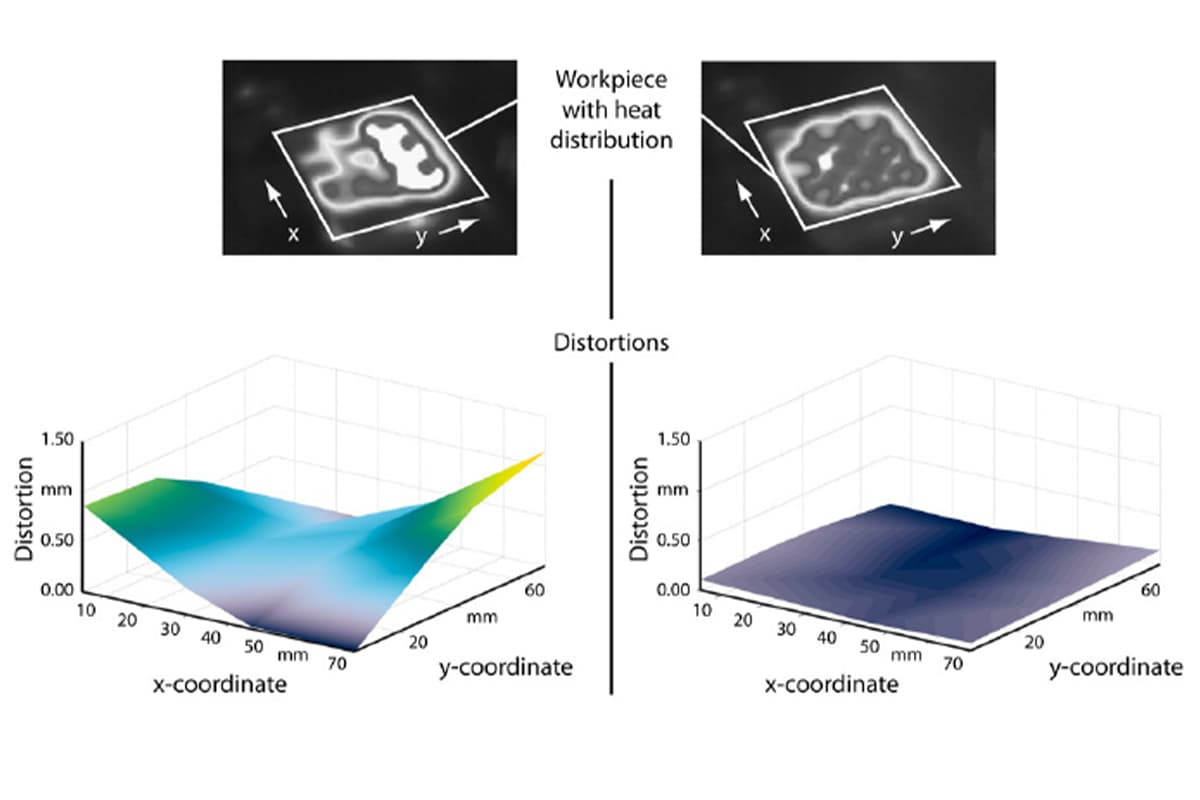
The rapid heating and cooling inherent to laser cutting introduces internal stresses. If these exceed the yield strength, irreversible deformation or warping can occur—especially common with thin sheets or elongated, intricate parts. Effective thermal deformation management involves minimizing total heat input through higher cutting speeds, pulse cutting, or optimized cutting sequences (e.g., grid or dispersed paths).

3. Pillar Three: Process Parameters – The Operator’s “Precision Control Panel”
If hardware is the “physique,” process parameters are the “skill.” A seasoned operator can fine-tune parameter combinations to push equipment performance to its limits, achieving optimal tolerance even within fixed hardware constraints.
(1) The Power–Speed–Frequency Triad: Finding the “Optimal Cutting Window” for Different Materials
Power, speed, and frequency form an interdependent core set of parameters that must be harmonized.
1)Power:
Defines energy delivered per unit time. Excessive power causes over-melting and ablation, leaving rough edges; insufficient power fails to cut through.
2)Speed:
Determines laser dwell time on the material. Excess speed prevents full penetration; too slow increases heat input, enlarging the HAZ and boosting deformation.
3)Frequency:
For pulsed lasers, this is the count of pulses per second. Higher frequency tends to yield smoother edges but adds heat accumulation; lower frequency reduces heat buildup but may produce jagged edges.
There’s no universal formula connecting these factors. Operators must experiment with material type and thickness to locate the optimal balance—known as the processing window.
(2) Assist Gas: How Nitrogen, Oxygen, and Air Influence Cut Quality and Dimensions
Assist gas does far more than expel molten debris—the gas actively shapes the chemical and physical environment during cutting.
1)Oxygen:
As an active gas, oxygen reacts exothermically with hot metal, adding chemical heat to markedly boost cutting speed (especially for carbon steel). Drawbacks include a thin oxide film on the cut surface and slightly rougher edges, making it unsuitable for parts requiring post-cut welding or coating.
2)Nitrogen:
Being inert, nitrogen does not react with metal—it simply uses high pressure to force molten material from the kerf. Known as “fusion cutting,” this produces bright, oxide-free, burr-free edges ready for direct welding. Downsides include high consumption, increased costs, and typically requiring more laser power.
3)Air:
A cost-effective compromise, air (roughly 80% nitrogen, 20% oxygen) offers moderate oxidation—less aggressive than pure oxygen. Cut quality is better than oxygen cutting but inferior to nitrogen, making it suitable for applications with looser edge requirements.
(3) Focal Position: How Small Adjustments Can Dramatically Affect Taper and Accuracy
Focal position—the vertical location of the laser’s narrowest point relative to the workpiece surface—has a decisive influence on kerf geometry.
1)Positive Focus (above the workpiece surface):
Commonly used for thin sheets, yielding narrower kerfs at the top surface.
2)Zero focal point (focus at the workpiece surface):
Delivers maximum energy concentration, making it ideal for tasks like engraving or marking.
3)Negative focal point (focus inside or below the workpiece):
A common approach for cutting thick materials. Positioning the focus at half to two-thirds of the material’s thickness helps achieve uniform kerf width from top to bottom, minimizes taper, and produces a more vertical cut edge—significantly improving dimensional accuracy for thicker plates.
4. Pillar Four: Environmental Factors – The “Invisible Killers” on the Production Floor
Even with the best equipment and processes, a poor manufacturing environment can undo all your hard work. Environmental conditions are among the most overlooked yet crucial elements in maintaining precision tolerances.
(1) Temperature Fluctuations: How Thermal Stability Affects Machine Accuracy
Both the machine and the workpiece expand and contract with temperature changes. Significant variations in workshop temperature—such as day-night differences or direct air conditioning—can cause micrometer-level deformations in the machine’s frame, beams, and guide rails, leading to positioning errors. For large machines aiming for micrometer precision, maintaining a constant environment (e.g., 20°C ±1°C) is essential. Steel expands roughly 12 micrometers per meter for every degree Celsius; on a 5-meter-long machine, a 5°C temperature change can theoretically cause an expansion or contraction of 0.3 mm.
(2) Vibration Interference: Isolating Vibration Sources Through Foundations and Damping Measures
Vibration is another major enemy of precision. Sources may originate within the machine itself (e.g., fans, pumps) or externally (e.g., nearby presses, forklifts in motion, equipment on upper floors). These vibrations can reach the cutting head, causing irregular laser beam movement relative to the workpiece, which manifests as ripples or jagged edges along the cut—severely compromising accuracy and surface finish.
(3) Solutions
1)Independent foundation:
Install a separate concrete base for ultra-high precision equipment, physically detached from the factory’s main structure to block floor-borne vibrations at the source.
2)Vibration isolation devices:
Use pneumatic or passive isolation tables/foot pads to effectively absorb and dampen vibrations arising from the ground or the machine itself, ensuring smooth and stable cutting operations.
IV. Measuring and Testing Tolerance in Laser Cutting
1. Common Tools and Techniques for Measuring Tolerance
Calipers and Micrometers
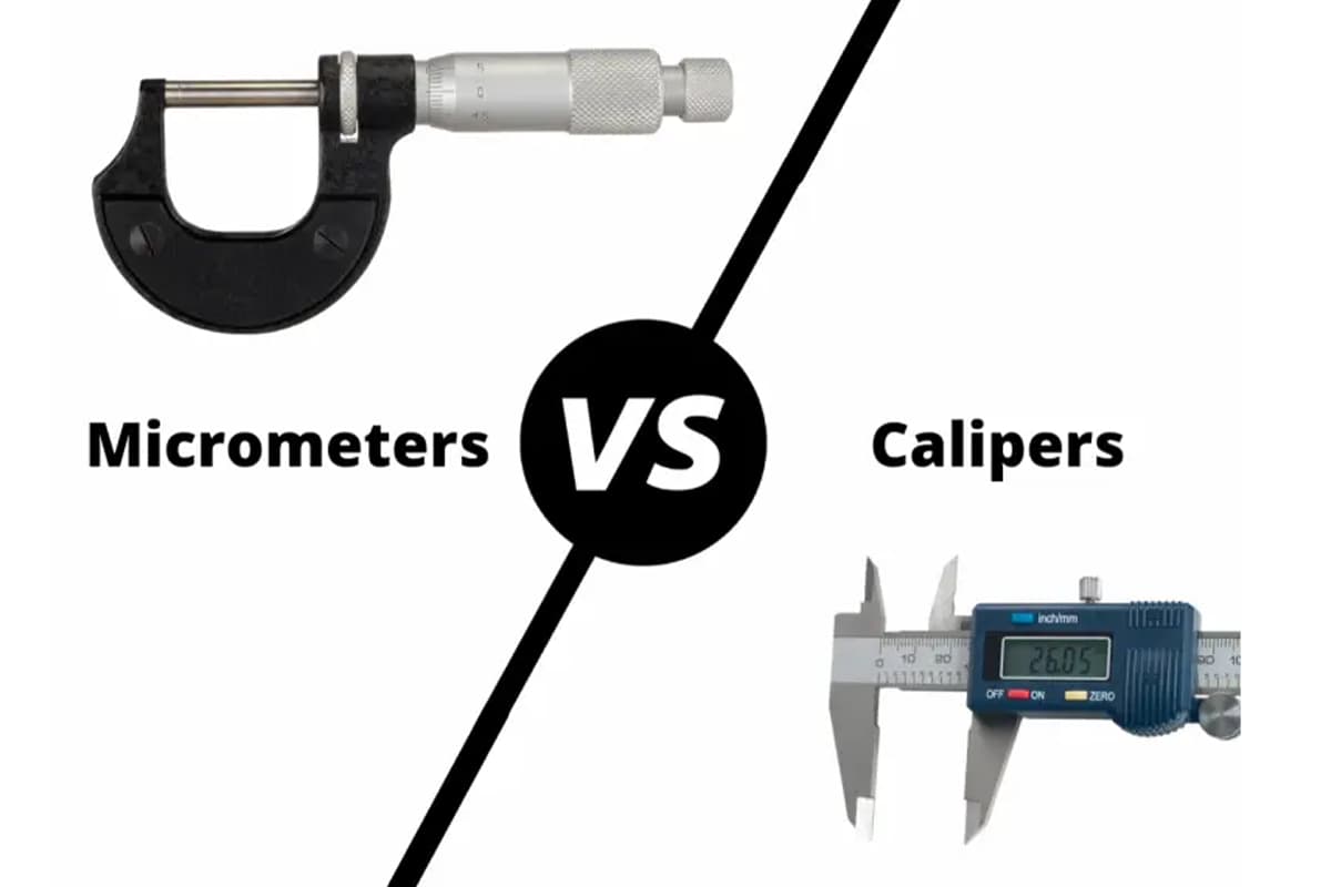
Vernier Calipers
Vernier calipers are precision instruments used to measure the dimensions of laser-cut parts with high accuracy. They can measure internal and external dimensions and depths, providing a quick and reliable means of checking tolerances.
Accuracy
- 50 Division Vernier Caliper: Accuracy is 0.02 mm
- 20 Division Vernier Caliper: Accuracy is 0.05 mm
- 10 Division Vernier Caliper: Accuracy is 0.1 mm
Example: Measuring the thickness of a laser-cut metal sheet to within 0.01 mm to ensure it meets the specified tolerance.
Micrometers
Micrometers offer even greater precision than vernier calipers, capable of measuring dimensions with an accuracy of up to 0.001 mm. They are particularly useful for measuring small features and thin materials where high precision is required.
- Example: In the aerospace industry, micrometers measure the thickness of turbine blades, ensuring they meet the tight tolerances required for safe and efficient operation.
Coordinate Measuring Machines (CMMs)
Coordinate Measuring Machines (CMMs) are advanced tools used to measure the geometry of an object by sensing discrete points on its surface with a probe(e.g., touch-trigger, scanning) .
CMMs provide highly accurate three-dimensional measurements and are especially valuable for complex geometries and critical tolerance parts. These machines often have an accuracy in the range of ±0.005 mm to ±0.001 mm.
Optical Comparators
Optical comparators (also known as profile projectors) use the principles of optics to compare the contour of a manufactured part against its design specifications.
By projecting a magnified image of the part onto a screen, deviations from the desired geometry can be visually inspected and measured. This method is highly effective for profile and surface measurements.
2. Regular Testing and Quality Control
Benefits of Regular Testing
- Consistency: Ensures each part produced meets the specified tolerances, resulting in consistent quality across batches.
- Defect Reduction: Identifies deviations early, reducing defects and rework, saving time and materials.
- Compliance: Ensures parts comply with industry standards and customer specifications, reducing the risk of non-compliance issues.
Quality Control Methods
- Statistical Process Control (SPC): Monitoring and controlling the production process using statistical methods. By tracking key parameters, manufacturers can identify trends and variations, allowing for timely corrections.
- First Article Inspection (FAI): Inspecting the first part produced in a batch to ensure it meets the specified tolerances. This helps verify the setup and parameters before full-scale production.
- In-Process Inspection: Checking parts at different stages during production. This helps identify deviations early and allows for timely corrections.
- Post-process inspection: This involves measuring parts after the cutting process using the tools mentioned earlier to validate conformance to tolerance specifications.
3. Measuring Tolerance in Different Materials
Metal Materials
Metal parts are typically measured using a combination of mechanical gauges (like micrometers) and CMMs. Due to the reflective nature of metals and their susceptibility to burrs and edges, precise calibration and surface preparation are critical for accurate measurements.
Laser micrometers, which use a laser beam to measure distance, can also be particularly effective for thin metal sheets and tubes.
Non-Metal Materials
For plastics, woods, and other non-metal materials, optical measuring techniques such as laser scanners and coordinate projectors are often employed.
These materials can deform under pressure, so non-contact measurement tools ensure that their true dimensions are captured without compromising their integrity.
V. Improving Laser Cutting Machine Tolerance
Enhancing the tolerance of laser cutting machines is essential for achieving superior precision and consistent product quality.
This section explores best practices and strategies that can be implemented to improve the tolerance capabilities of laser cutting machines, encompassing aspects of machine setup, operator training, and technological advancements.
1. Best Practices for Machine Setup and Calibration
Proper machine setup and calibration are fundamental steps in achieving tight tolerances in laser cutting. Here are some best practices to follow:
Initial Setup
- Alignment: Ensure perfect alignment of the laser beam with the cutting head. Misalignment can cause uneven cuts and deviations from the desired tolerance. For example, a company improved its alignment accuracy by using a laser alignment tool, which resulted in a 20% improvement in cut quality.
- Focus Adjustment: Accurate focus adjustment is crucial. The focal point of the laser beam should be precisely set according to the material thickness and type to achieve clean cuts with minimal kerf width. Use tools like a focus gauge to ensure precision.
- Beam Quality: Regularly check the beam quality using diagnostic tools to ensure it maintains a consistent profile and intensity. High beam quality is essential for precise cuts.
Routine Calibration
Proper calibration is essential for maintaining high tolerance levels. Here are specific calibration steps:
- Laser Power Calibration: Periodically calibrate the laser power output to ensure it matches the settings on the control panel, maintaining consistent cutting performance.
- Motion System Calibration: Calibrate the motion systems (e.g., X, Y, and Z axes) for accurate positioning and movement. Deviations can lead to inaccuracies in the cut dimensions.
- Optics Maintenance: Clean and replace lenses and mirrors as needed to maintain optimal beam transmission and focus. Dirty or damaged optics can degrade beam quality and affect tolerance.
In addition to regular calibration, proactive maintenance plays a crucial role in ensuring high tolerance.
2. Training and Skill Development for Operators
Well-trained operators are critical to achieving and maintaining high tolerance levels in laser cutting. Here are some strategies for effective training and skill development:
Comprehensive Training Programs
- Initial Training: Provide comprehensive initial training for new operators, covering machine operation, calibration procedures, maintenance routines, and safety protocols.
- Advanced Training: Offer advanced training modules focused on specific aspects such as optimizing cutting parameters for different materials, troubleshooting common issues, and using advanced software features.
Continuous Skill Development
- Regular Workshops: Conduct regular workshops and training sessions to keep operators updated with the latest technologies, techniques, and best practices in laser cutting.
- Certifications: Encourage operators to pursue relevant certifications that validate their skills and knowledge in operating laser cutting machines.
Hands-On Experience
- Practical Sessions: Facilitate hands-on training sessions where operators can practice setting up, calibrating, and maintaining the machines. Real-world experience is invaluable in honing their skills.
- Mentorship Programs: Implement mentorship programs where experienced operators guide and support less experienced colleagues, fostering knowledge sharing and skill enhancement.
3. Advanced Technologies and Software Solutions
Automated Calibration Systems
Incorporating automated calibration systems can greatly enhance the precision of laser cutting machines. These systems use sensors and feedback loops to constantly monitor and adjust the laser beam and machine components, ensuring optimal alignment and focus without manual intervention. This automation reduces human error and improves consistency in achieving desired tolerance levels.
High-Resolution Imaging and Feedback
Advanced imaging technologies, such as high-resolution cameras and laser scanners, can provide real-time feedback on the cutting process.
These systems detect deviations from the programmed paths and make on-the-fly adjustments to maintain tight tolerances. Implementing such technologies enhances the capability to produce intricate and precise cuts consistently.
Intelligent Software Solutions
Laser cutting software has evolved to include sophisticated algorithms that optimize cutting paths, adjust for material inconsistencies, and predict potential deviations. Integrating intelligent software solutions that support adaptive learning and process simulation can aid in identifying and mitigating tolerance issues before they affect production.
VI. Challenges and Solutions in Achieving Optimal Tolerance
1. Challenges in Achieving Optimal Tolerance
Thermal Distortion
Thermal Distortion is one of the most prevalent issues affecting laser cutting tolerance. The heat generated by the laser can cause the material to expand and contract, leading to warping or changes in dimensions.
- Example: When cutting thick metal sheets, the localized heat input can cause the edges to expand and contract unevenly, leading to warping and deviations from specified tolerances. For instance, a 10mm thick steel sheet might warp by 0.2mm at the edges.
Solution:
- Heat Management: Utilize techniques such as pulsed laser cutting, where the laser is operated in short bursts, reducing the overall heat input and minimizing thermal distortion.
- Cooling Systems: Implement effective cooling systems to dissipate heat quickly and maintain the material's structural integrity.
Kerf Variation
Kerf Variation refers to inconsistencies in the width of the cut, which can affect the fit and function of the parts.
- Example: Variations in kerf width can lead to parts that do not fit together as intended, especially in applications requiring tight tolerances like aerospace components.
Solution:
- Consistent Parameters: Ensure consistent laser power, speed, and focus settings throughout the cutting process to maintain uniform kerf width.
- Beam Quality Monitoring: Regularly check and adjust the laser beam quality to ensure it remains consistent, minimizing kerf variation.
Material Inconsistencies
Different batches of materials can have varying properties, such as thickness and composition, leading to challenges in maintaining consistent tolerance.
- Example: A batch of stainless steel with slight variations in thickness can result in cuts that deviate from the specified tolerances.
Solution:
- Material Certification: Source materials from certified suppliers with strict quality control measures to ensure consistency.
- Adaptive Control Systems: Implement adaptive control systems that adjust cutting parameters in real-time based on material properties, ensuring consistent results.
Machine Wear and Tear
Over time, laser cutting machines can experience wear and tear, affecting their precision and ability to maintain tight tolerances.
- Example: Worn-out motion systems or misaligned optics can lead to inaccuracies in the cutting process.
Solution:
- Preventive Maintenance: Implement a structured preventive maintenance schedule that includes daily, weekly, and monthly inspections. Regularly check for worn-out motion systems, misaligned optics, and laser source deterioration to prevent any decline in cutting quality.
- Component Replacement: Replace worn or damaged components promptly to maintain the machine's performance and precision.
Environmental Factors
Environmental conditions such as temperature fluctuations, humidity, and air quality can impact laser cutting tolerance.
- Example: High humidity can affect the laser optics and the material being cut, leading to variations in the cut dimensions.
Solution:
- Controlled Environment: Maintain a controlled environment with stable temperature and humidity levels to minimize their impact on the cutting process.
- Air Filtration Systems: Use air filtration systems to keep the cutting area free from dust and contaminants that could affect the laser optics and material.
2. Solutions for Overcoming Tolerance Challenges
Routine Maintenance and Upgrades
Regular maintenance schedules should be strictly followed to mitigate the effects of wear and tear. This includes lubricating moving parts, replacing worn components, and regularly cleaning and aligning optical elements.
Upgrading hardware and software can also enhance machine performance and tolerance capabilities. Emerging technologies, such as improved beam delivery systems, can provide more stable and precise cutting operations.
Material Quality Control
Implementing rigorous quality control practices for incoming materials can help minimize variability. This includes pre-inspection of material batches for consistency in thickness, density, and composition.
Standardizing material suppliers and batch tracking can also reduce variability and provide more predictable cutting results.
Advanced Cooling Systems
To address thermal effects, integrating advanced cooling systems can help manage and dissipate heat more effectively. Water-cooled laser heads, for example, can reduce thermal distortion by maintaining a stable temperature during cutting.

Additionally, implementing real-time thermal monitoring and adaptive control systems can dynamically adjust cutting parameters to compensate for heat buildup.
Environmental Controls
Optimizing the working environment is crucial for maintaining consistent laser cutting performance. This involves climate control solutions to regulate temperature and humidity, and air filtration systems to keep the workspace free from dust and particulates.
Creating a stable and clean environment can significantly enhance the precision and reliability of the cutting process.
Process Optimization and Automation
Implementing process optimization technologies such as predictive maintenance and automated calibration systems can significantly improve tolerance maintenance.
These technologies utilize sensors and algorithms to predict potential issues and automate adjustments, ensuring consistent machine performance. Process automation also minimizes human error and enhances repeatability, leading to better tolerance adherence.
VII. FAQs
1. What are the differences in tolerance between CO2 and fiber laser cutting machines?

CO2 and fiber laser cutting machines differ fundamentally in their technology and the materials they effectively process, which impacts their achievable tolerances.
CO2 lasers are versatile, capable of cutting a wide range of materials including metals, plastics, and organics, but their beam properties typically result in broader tolerance levels.
In contrast, fiber lasers offer superior precision and are particularly advantageous for cutting metals due to their higher power density and effective absorption by metal surfaces.
This results in tighter tolerance levels with minimal thermal distortion, making fiber lasers more suitable for applications requiring stringent precision.
For a detailed comparison of specific models and their capabilities, feel free to browse our technical brochures.
2. Are there specific standards for laser cutting tolerance in the automotive industry?
Yes, the automotive industry adheres to specific standards for laser cutting tolerance to ensure the quality, safety, and interoperability of components.
These standards often align with broader international quality control standards like ISO 9001 for quality management systems and IATF 16949, specifically for automotive quality management.
Tolerances in the automotive sector are tightly controlled to ensure that parts fit precisely within complex assemblies, contributing to the overall performance and safety of the vehicle.
Manufacturers often implement rigorous quality control measures, including regular inspection and testing, to ensure compliance with these standards.
3. What advanced technologies can help improve laser cutting tolerance?
Several advanced technologies have been developed to enhance laser cutting tolerance. Automated calibration systems utilize sensors and feedback loops to continuously monitor and adjust machine parameters, ensuring precise alignment and focus.
High-resolution imaging and laser feedback systems provide real-time monitoring during the cutting process, allowing for immediate corrections to maintain tight tolerances.
Intelligent software solutions further optimize cutting parameters, compensating for material inconsistencies and environmental variations, and supporting predictive maintenance to prevent deviations over time.
Integrating these technologies into laser cutting processes leads to higher precision, improved efficiency, and reduced error rates.
If you want to learn how these advanced solutions can be applied to your specific projects, please contact us for a consultation.


