I. Introduction
Welcome to the ultimate guide to mastering the hydraulic press brake. This machine is far more than a mere tool—it’s an intelligent system that merges powerful hydraulics with advanced digital control to form metal with unmatched accuracy.
While its immense force stems from Pascal’s law, real precision comes from the harmonious integration of its key components: the CNC “brain,” the servo-driven back gauge, and meticulously engineered tooling. Together, they transform raw sheet metal into complex, high-quality parts.
But genuine mastery involves more than understanding how the press brake functions. It requires disciplined preparation, in-depth knowledge of bending techniques, and an unwavering focus on safety.
This guide takes you from basic principles to advanced practices—covering everything from initial setup and safety inspections to resolving common forming issues and connecting your operations to the smart factory ecosystem of Industry 4.0.
Whether you’re just starting out or already an experienced technician, this resource will help you boost productivity, ensure perfect results, and maintain a zero-accident workspace. Let’s begin your evolution from operator to expert.
II. Mastering Operations: From Single Bends to Complex Workpiece Workflows
2.1 The Five-Step Foundation for Bending
In today’s efficiency-driven manufacturing environment, trial and error is the costliest mistake. This time-tested “Five-Step Method” is the golden rule for ensuring first-part accuracy and establishing consistency across mass production.
Step 1: Parameter Decoding & Strategy Preview
- Blueprint Analysis: Treat the drawing as your operational map. The top priority is to identify three core parameters: material type (e.g., low-carbon steel, stainless steel, or aluminum), sheet thickness (t), and the target bending angle with inner radius (R).
- Tool Selection: Choose tools according to material properties. A highly effective industry guideline—often kept as an insider secret—is the “Thickness Multiplication Rule.” For standard carbon steel with tensile strength around 450 MPa, the lower die’s V-opening width (V) should be 8 times sheet thickness (V ≈ 8t). For tougher stainless steel, widen that to 10–12 times (V ≈ 10–12t), while for softer aluminum, reduce it to about 6 times (V ≈ 6t). Selecting the correct V-opening ensures an optimal balance between forming quality and required tonnage.
- Tonnage Calculation: Respect the machine’s longevity. Use the CNC’s built-in tonnage calculator or reference chart to determine precise pressure based on bending length, material strength, sheet thickness, and chosen V-width. Always remember: overloading causes irreversible damage to the press brake—an absolute prohibition in professional operation.
Step 2: Machine Setup & Calibration
- Tool Installation & Alignment: Securely mount the upper and lower dies. Alignment is the soul of this process—ensure the upper punch tip and the lower die’s V-groove centerline align perfectly along their entire length. This prevents inconsistent bending angles between ends.
- Back Gauge Programming: Set precise back gauge coordinates according to the flange dimensions in the drawing.
- Program Input: Translate all decoded parameters—material, tooling, angle, back gauge position, ram speed, and bottom dead point depth—into the CNC controller’s operating language.
Step 3: Material Preparation & Positioning
- Material Check: Inspect the sheet surface to ensure it’s clean and undamaged. Measure actual thickness with a micrometer, as even small deviations within a batch can affect the final bend angle.
- Positioning Consistency: Place the sheet smoothly and press inward until its edge rests firmly and flush against the back gauge fingers. The operator’s consistency in movement and pressure during each load is an invisible but crucial factor for maintaining uniform flange dimensions in large-scale production.
Step 4: Test Bend & Data Acquisition

- Use Scrap for Testing: Never, ever use a production part for the first test bend. This rule serves both cost control and process integrity. Always test with scrap material identical to the production workpiece.
- Execution & Inspection: Run the bending cycle. Afterward, measure the trial piece’s actual bend angle and flange length using a high-precision digital protractor and caliper.
Step 5: Compensation & Program Lock
- Managing Springback: Due to metal elasticity (springback), the first bend rarely matches the target angle exactly. Based on measurements, enter a compensation value in the CNC system. For example, if the target is 90° and the measured angle is 91°, springback equals 1°. Adjust the program so the machine over-bends to 89°, which will recover to a perfect 90° after springback.
- Iterative Verification: Repeat the test with new scrap until the bend angle and dimensions are fully within drawing tolerance.
- Program Lock: Once confirmed, immediately lock the program to preserve consistency across hundreds or thousands of subsequent parts.
2.2 In-Depth Analysis of Core Bending Techniques
Different bending techniques cater to varying accuracy requirements, materials, and productivity goals. Understanding their fundamental differences marks the critical step from simply “using” a press brake to truly mastering its operation.
| Feature | Air Bending | Bottoming | Coining |
|---|---|---|---|
| Process Description | The punch presses the sheet into the die without touching the bottom of the V groove. The sheet contacts only the punch tip and the shoulders of the V groove, creating a "three-point bend." | The punch presses the sheet until it nearly touches the bottom of the V groove, bringing its shape closer to the die angle and slightly compressing the internal radius. | The punch applies extreme force to fully press the sheet into the bottom of the V groove, similar to minting a coin. It plastically restructures the material’s microstructure for a definitive shape. |
| Bend Angle Control | Determined by the punch depth (stroke) relative to the die. CNC systems offer extremely precise and flexible control. | Primarily dictated by the die’s own angle, though affected by springback and adjustable by pressure. | Fully dictated by the die angle, offering the highest level of accuracy. |
| Required Tonnage | Lowest; minimal wear on machine and tooling. | Moderate; roughly 3–5 times that of air bending. | Very high; approximately 5–10 times that of air bending, placing substantial stress on both machine and tooling. |
| Springback | Greatest and most variable; highly sensitive to changes in material thickness and hardness, requiring precise CNC compensation. | Smaller; partially countered by compressing the internal radius below its natural value. | Virtually none; massive pressure removes internal stresses, eliminating elastic recovery. |
| Advantages | Extremely versatile; one set of tools can create multiple angles; efficient with widely compatible tooling. | Greater accuracy and repeatability than air bending; better control of springback. | Highest accuracy and consistency; no need for springback compensation. |
| Drawbacks | Accuracy is sensitive to material uniformity; springback compensation algorithms are complex. | Requires higher tonnage; die angles must match target angles, reducing flexibility. | Very high tonnage demands; best suited for thin sheets and low loads; severe wear on machines and tooling; generally not recommended for modern CNC press brakes. |
| Expert Insight | Modern CNC press brakes are almost exclusively designed for air bending, leveraging precise stroke control and advanced angle compensation databases for optimal efficiency and accuracy. | Bottoming acts more as a fine-tuning technique, using pressure to yield the material for a more stable angle, still valuable in specific contexts. | "Coining" draws its name from minting coins—it’s more than bending; it’s a complete reformation of the material’s microstructure, requiring immense energy. |
2.3 Strategies for Processing Complex Workpieces
When a part features multiple bends, non-parallel bends, or enclosed shapes, simple single-bend operations are no longer sufficient. At this stage, you must elevate your approach to a strategic level—planning the entire process like a chess grandmaster.
Offline Programming & 3D Simulation:
This is the “secret weapon” for modern complex workpiece processing. Operators no longer spend costly machine time programming and experimenting; instead, they complete all tasks using dedicated office software tools (such as DELEM, ESA, CYBELEC offline platforms).
Principles of Bend Sequence Planning:
Inside Out: For box or channel parts, start with the shorter internal bends, then complete the longer external bends. Doing the long bends first can block access for later internal bends.
Tackle the Difficult First: Address bends that could limit subsequent operations or that require special positioning before moving on to simpler bends.
Minimize Flipping: Organize the sequence to reduce how often the operator has to flip or rotate the workpiece, boosting efficiency and reducing risks of mistakes or injury.
Handling Special Geometries:
High Flanges / Deep Boxes: Use a Gooseneck Punch or an extended-height die to allow clearance for previously bent sections.
Angled Edge Bending: Employ multi-axis backgauge systems (X, R, Z1, Z2) where fingers can move independently to accommodate slanted edges.
U-Channels or Closed Shapes: Final bends may trap the part in the die. Counter this by using step bending techniques or special one-sided dies for the last bend.
2.4 Quality Control: Ensuring Every Product Meets the Standard
Quality control is not a final inspection after production—it’s an ongoing process throughout manufacturing. It ensures exceptional consistency and precision from the first item to the last.
In-Process Monitoring & First Article Inspection (FAI)
- First Article Inspection (FAI) is mandatory and serves as the guardian of quality. Do not begin mass production until the test bend is confirmed fully compliant.
- Periodic Sampling: For long production runs, inspect parts periodically (such as every 20 pieces or hourly) to check angles and dimensions, as machine heating, tool wear, or material batch variations can cause subtle shifts.
Precision Measurement Tools & Methods
- Angle Measurement: Beyond traditional protractors, modern laser angle measurement systems can check angles in real time during bending, feed data to the CNC, and automatically compensate for springback—achieving ±0.3° accuracy or better.
- Dimensional Measurement: Precision digital calipers and height gauges are basic tools. For complex or high-precision parts, a Coordinate Measuring Machine (CMM) is the gold standard for final dimensional verification.
- Straightness Inspection: For long parts, check straightness after bending using long rulers and feeler gauges to detect “boat” or “barrel” distortions caused by insufficient crowning compensation.
Managing Material Variations
- Batch Tracking: Even when specifications match, subtle differences in hardness, thickness, or composition between material batches can alter springback. Conduct new trial bends and adjust angle compensation for each batch.
- Grain Direction: Bending along the rolling grain requires less force than bending across it, yet it is more prone to causing fine cracks on the outer bend surface. This factor should be taken into account during design and layout planning, aiming—where possible—to align the bend line with the grain direction or to set it at a deliberate angle.
- Operator Skill and Responsibility: A highly trained, experienced operator is an irreplaceable element of effective quality control. By relying on auditory cues, tactile feedback, and visual inspection, they can detect subtle irregularities in the machine or process. Implementing rigorous Statistical Process Control (SPC), systematically recording fluctuations in critical dimensions and angles, and using data analysis to continuously fine-tune process parameters represent a sophisticated pathway to achieving exceptional quality management.
III. Advanced Optimization: Boosting Efficiency, Precision, and Tackling Common Challenges
Once you’ve mastered the fundamentals, true value creation begins. The leap from skilled technician to manufacturing master lies in transforming the bending unit from a mere execution point into a high-efficiency, high-precision, low-waste profit engine. This requires breaking free from a “button-pushing” mindset and adopting a systems-level optimization approach—examining the entire workflow from programming to finished part with fresh, strategic eyes.
3.1 Strategies for Doubling Efficiency: Cutting Downtime and Boosting Output
In bending operations, the actual time the ram moves—and thus generates value—is surprisingly small. Most time is consumed by setup, tool changes, programming, test bending, and material handling—all non-value-adding activities. The essence of efficiency improvement is the relentless elimination of all non-bending time.
Implement Lean Setup (SMED – Single-Minute Exchange of Die)
Offline Programming: The Efficiency Game-Changer. Perhaps the most disruptive efficiency tactic. While Machine A is producing Part X, a technician can use dedicated offline software to prepare programs, 3D bending simulations, and collision checks for Parts Y and Z from a workstation in the office. This ensures the machine never sits idle waiting for programming—achieving “zero programming downtime” and pushing utilization to the limit.
Rapid Tool Change Systems: Cutting Minutes to Seconds. Traditional bolt-based tool changes are slow, tiring, and reliant on operator skill. Investing in hydraulic or pneumatic quick-change systems delivers lasting returns. Such systems can slash changeovers from frustrating tens of minutes to mere minutes—or even seconds. A single action simultaneously clamps or releases an entire tool set, boosting speed and standardizing processes.
Tool Standardization with 5S Management: Develop a well-organized, visually clear “tool library.” Use racks with contour markings for easy identification and standardize common tool combinations wherever possible. Operators should be able to locate the exact tool in seconds rather than rummaging through a chaotic pile.
Optimize Production Workflow

Smart Sequencing and Batch Consolidation: Approach production scheduling like a chess match. Group jobs that require the same tooling, materials, or similar bending angles, running them back-to-back. Every clever consolidation saves a costly tool-change downtime.
Automation Assistance: Unlocking Productivity. For highly repetitive, large-batch orders, robotic bending cells are the ultimate future-proof solution. Robots can operate 24/7, performing loading, precision positioning, dynamic tracking, complex flipping, and finished-part stacking with consistent accuracy far beyond human ability. This means exponential efficiency gains and frees operators from heavy manual labor to focus on quality control, workflow improvement, and other creative, high-value tasks.
Harness the Full Potential of the CNC Controller
Activate the Intelligent Database: Modern CNC controllers are more than command executors—they’re knowledge hubs. Input precise tensile strength and micrometer-measured thickness to let the built-in expert database calculate accurate springback compensation, reducing trial bends from “several” to “one” or even “none.”
Leverage Advanced Functions: Master and apply advanced CNC features like automatic angle measurement and correction systems and dynamic hydraulic crowning control. These give the machine self-awareness and real-time adjustment capability, eliminating deviations during production and significantly cutting downtime caused by manual intervention.
3.2 Diagnosing and Preventing Common Bending Defects
Defect 1: Inconsistent Bending Angles (Angle Drift During Mass Production)
Typical Diagnosis: Uneven material thickness or hardness; worn-out tooling.
Deep/Hidden Causes:
- Thermal expansion and contraction of hydraulic oil: At startup, the oil is cold and more viscous; continuous operation heats it up, reducing viscosity. This change affects the servo valve’s response and slide positioning by microns—enough to cause angular deviations of about 0.2°–0.5°.
- Invisible fluctuations in power supply voltage: During peak electricity usage, small voltage variations in the factory grid can disrupt the stability of the servo valve’s electromagnet, leading to subtle positioning errors in the ram.
Expert-Level Solutions:
- Establish a “warm-up” standard: Before machining precision parts, allow the press brake to run idle for 15–20 minutes so the hydraulic system reaches thermal stability (around 45°C) before checking the first workpiece.
- Use an independent voltage regulator: Install an industrial-grade stabilizer dedicated to high-precision CNC press brakes to isolate grid fluctuation and guarantee servo command consistency.
Defect 2: Workpiece Cracking (Especially at the Bend Root)
Typical Diagnosis: Bend radius (R) too small or poor material ductility.
Deep/Hidden Causes:
- The “fatal parallel” between bend line and rolling direction: Sheet metals have directional grain texture from rolling. When the bend line runs parallel to that texture, ductility in that direction drops by over 50%, dramatically increasing the likelihood of cracking.
- Hardened layer at cut edges: Plasma or laser cutting creates a very thin but brittle martensitic layer (heat-affected zone) along the edge. If this hardened zone lies on the outer tensile side of the bend, it serves as a crack initiation point.
Expert-Level Solutions:
- Optimize nesting orientation: Anticipate bending requirements during layout planning to ensure major bend lines intersect the rolling direction at either 45° or 90°.
- Edge pretreatment: For high-strength steels or critical safety components, lightly grind the outer edge along the bend line using a wheel or angle grinder (around a 0.2 mm chamfer) to completely remove the brittle hardened layer.
Defect 3: Inaccurate Flange Dimensions (Unequal or Offset Ends)
Typical Diagnosis: Backgauge misalignment or improper material feed by the operator.

Deep/Hidden Causes:
- Nonlinear error in the backgauge beam: Over time, repeated positioning impacts can cause slight permanent bending of the backgauge beam. Consequently, accuracy at its ends may differ from the calibrated center point.
- Internal stress release in the sheet: Large sheets often warp minutely after shearing or laser cutting due to internal stress release, preventing them from sitting flush against the backgauge—effectively introducing misalignment.
Expert-Level Solutions:
- Perform segmented calibration: Don’t only calibrate at the midpoint of the backgauge’s travel. Calibrate separately at key positions (e.g., 20%, 50%, and 80% of stroke) and apply corresponding error compensation to correct beam nonlinearity.
- Upgrade positioning devices: For thin or large sheets, use backgauges with pneumatic clamping or height-adjustable fingers. After positioning, they press the sheet firmly against the die surface, eliminating errors caused by warping.
Defect 4: Scratches or Imprints on Finished Surfaces (Especially Stainless Steel and Aluminum)
Typical Diagnosis: Chips or debris on the die; improper handling.
Deep/Hidden Causes:
- Work hardening of the lower die’s V-groove shoulders: Prolonged bending—particularly of high-strength materials—causes the two shoulders of the V-groove to harden and wear subtly under extreme pressure, forming barely visible sharp edges that act like a file against the sheet surface.
- Microscopic tearing from “galling”: When bending stainless steel, microscopic cold welding can occur between the sheet and the die surface under high pressure. As the slide retracts, these bonds tear apart, damaging both surfaces and leaving scratches.
Expert-Level Solutions:
- Regularly recondition die shoulders: Implement a maintenance routine involving fine polishing of V-groove shoulders with oil stones or ≥800-grit abrasive paper, following the groove direction to remove sharp edges and restore smooth transitions.
- Prevent direct metal-to-metal contact: For stainless steel, prefer dies treated with nitriding or coated with friction-reducing layers such as TiN. Alternatively, a cost-effective method is to apply a high-strength polyurethane protective film to the lower die, creating a cushioning layer.
3.3 Finishing Techniques for Specific Materials
Different metals have distinct “personalities.” Treating them all the same is the culprit behind skyrocketing scrap rates. Mastery means understanding each material as a chef understands his ingredients—handling each with precision, respect, and awareness of its unique traits.
Stainless Steel
Challenges with stainless steels such as 304 and 316 stem primarily from their high strength, severe springback, and significant work-hardening tendency.
- Allow for tonnage margin: Bending stainless steel requires roughly 1.5 times the tonnage needed for low-carbon steel of the same thickness. Before taking on a job, ensure the press has at least a 20% tonnage reserve.
- Use wider V-dies to tame springback: To manage its pronounced springback (up to 3°–5°) and reduce tonnage, select a V-opening width of 8–10 times the sheet thickness (V = 8–10t). Note that this increases the bend radius, which should be considered during product design.
- The hard truth about die selection: Stainless steel’s tendency to adhere makes die choice critical. Use high-hardness dies (above 42 HRC), finely polished surfaces, or those with nitriding/TiN coatings to resist scratching and galling.
- Slow down – gentle force wins: Lowering the bending speed reduces frictional heat and work hardening, allowing smoother plastic deformation and more consistent angles.
Aluminum
Aluminum alloys like 5052 and 6061 are soft, lightweight, yet extremely prone to surface marking—treat them as you would a delicate artwork.
- Surface protection is paramount: Aluminum surfaces mark easily. Cover the lower die’s V-groove with a non-marring bending film, or use nylon/polyurethane die inserts. Prior to operation, ensure dies, tables, and gloves are impeccably clean and dust-free.
- Beware of cracking in hardened aluminum: For heat-treated grades like 6061-T6, ductility drops sharply. The bend radius must not be too small—a safe guideline is R ≥ 1–2t (radius one to two times sheet thickness). Otherwise, micro-cracks may appear along the tensile side.
- Respect the rolling direction: Aluminum’s anisotropy is even more pronounced than steel’s. Avoid sharp or small-radius bends parallel to the rolling direction whenever possible.
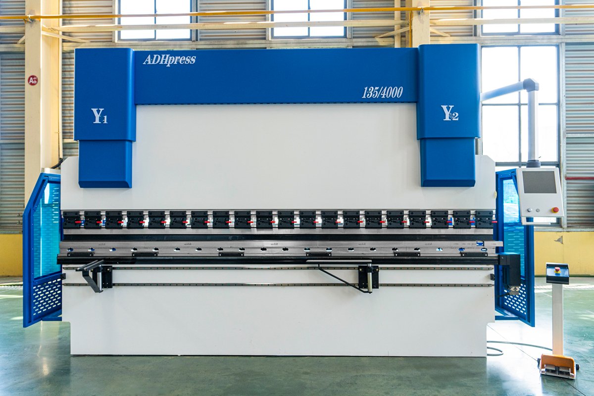
High-Strength Steel (HSLA/AHSS)
High-strength low-alloy (HSLA) steel and advanced high-strength steel (AHSS) are cornerstones of modern lightweight industrial design—yet they represent the ultimate challenge on the bending floor. Their hallmark characteristics are exceptionally high tonnage requirements coupled with substantial, often unpredictable springback.
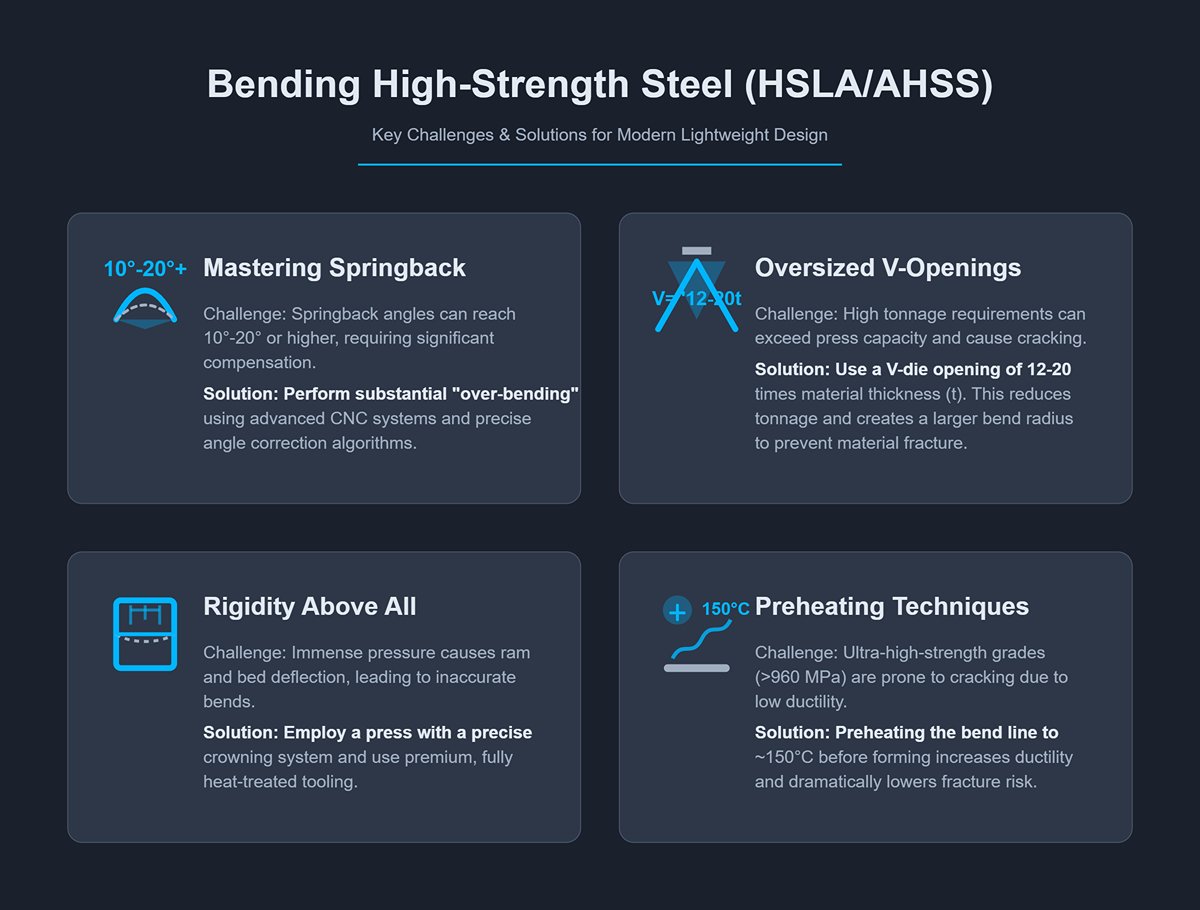
- Mastering extreme springback: Springback angles can reach 10°–20° or even higher, meaning you’ll need to perform significant “over-bending” to compensate. This puts extraordinary demands on the CNC system’s springback database and angle correction algorithms, as well as on the operator’s skill and judgment.
- Opt for oversized V-openings: To achieve forming within your press’s rated tonnage, the V-die opening may need to be 12–20 times the material thickness (V = 12–20t). This isn’t just to reduce tonnage—it ensures a sufficiently large bend radius to distribute stress and prevent cracking.
- Rigidity above all else: Bending high-strength steel demands immense pressure per unit length, pushing machine frame rigidity and tooling strength to the limit. The press should feature an efficient, precise crowning system—whether hydraulic or mechanical—to counter deflection; without it, the workpiece will suffer significant under-bending in the center due to ram and bed deformation. Tooling must be made from premium, fully heat-treated tool steels engineered specifically for high-strength applications.
- Leverage preheating techniques: For certain ultra-high-strength grades (yield strength above 960 MPa), preheating along the bend line to around 150°C before forming can noticeably increase ductility, dramatically lowering the risk of cracking.
IV. Maintenance and Safety
Preventive Maintenance: A Schedule to Maximize Equipment Uptime
At the heart of preventive maintenance (PM) lies a simple yet transformative idea: turning maintenance from costly “firefighting” into a disciplined form of “health management.” Far from being an expense, PM represents the smartest investment you can make in your equipment’s availability, precision, and longevity. The following four-level maintenance schedule, built on industry best practices, serves as your roadmap to eliminating unexpected downtime.
Level 1: Daily / Per Shift Inspection (Performed by Operator)
This is the operator’s responsibility and the foundation of smooth daily production. Spend five minutes before startup to earn peace of mind for the rest of the day.
- Clean & Check: Walk around the machine thoroughly. Look for visible hydraulic leaks (oil marks or drips), loose bolts, or worn cables. Clean the workstation, tooling, and floor of any metal debris or oil stains. A clean workspace is the most sensitive “early-warning sensor” for equipment failure.
- Safety Device Function Test (Safety First): This is your daily, non-negotiable lifeline. Use a test rod at different speeds and angles to verify that the safety light curtain or laser guard reliably stops the ram upon any intrusion. Test and reset every emergency stop button.
- Fluid Levels & Temperature: Check the oil level through the hydraulic tank gauge, ensuring it remains within the normal range. Monitor oil temperature carefully—if it rises abnormally, stop the machine immediately for inspection.
- Tooling Condition: Inspect the upper and lower dies in use to confirm there are no chips on the edges or cracks on the die body.
Level 2: Weekly Inspection
This deeper routine inspection aims to eliminate potential issues before they develop.
- Lubrication: Following the manufacturer’s lubrication chart, clean and apply the recommended grease or oil to all critical moving parts—such as guides, ram slides, backgauge ball screws, and linear bearings.
- Fasteners: Check the clamping system for the tooling, backgauge connecting bolts, and other primary mechanical fasteners. Continuous vibration can gradually loosen bolts over time.
- Filters: Inspect the air filter on the hydraulic power unit and the line pressure filters. If blockage indicators show warning signals, address them promptly.
Level 3: Monthly Inspection

This level involves a more detailed “diagnostic check” of core systems.
- Hydraulic System: While the machine is running, listen closely for unusual noises or vibrations from the hydraulic pump and motor. Clean the radiator to maintain cooling efficiency, and check all hose joints for leaks—fix any seepage immediately.
- Electrical Cabinet: Ensure the main power is completely disconnected and proper LOTO procedures are followed before opening. Use a vacuum or low-pressure compressed air to remove dust from fan filters and internal components—an essential step in preventing electrical failures and fire hazards.
- Accuracy Verification: Using calibration tools, check the backgauge positioning accuracy and repeatability. Verify the parallelism between the ram and the worktable to ensure machine geometry remains stable.
Level 4: Semi-Annual to Annual Professional Maintenance
This is a comprehensive “full-body examination,” with certain tasks strongly recommended to be performed by manufacturer-certified service engineers.
- Oil & Filter Change: Depending on workload (typically every 2,000–4,000 hours) or at least once a year, completely replace the hydraulic oil and all filters. A commonly overlooked but critical rule is: never mix hydraulic oils of different brands or specifications—their additives may react chemically, corroding seals and clogging precision valves.
V. Conclusion
In conclusion, this guide has provided a comprehensive roadmap to mastering the hydraulic press brake. Exceptional bending performance is achieved through a deep understanding of the equipment, strict adherence to process, continuous optimization for efficiency, and an unwavering commitment to safety.
Mastering these principles is the first step; choosing the right partner is the next. Since 1982, ADH Machine Tool has provided cutting-edge, reliable sheet metal equipment and expert technical guidance. Whether you are upgrading your production line or purchasing your first CNC press brake, our team offers comprehensive support, from equipment selection to operator training. For a detailed look at our product specifications, we invite you to view our Brochures.
It's time to elevate your manufacturing capabilities. Contact us today for a free quote and professional consultation, and let ADH help make excellence the new standard in your workshop.


