I. Introduction
Mastering professional terminology is of vital importance in the sheet metal industry. Only by understanding the concept of each technical vocabulary can we communicate and accomplish the task better.
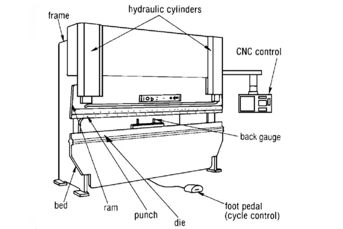
Press brake is a machine tool commonly used in the sheet metal fabrication industry. It can bend the metal sheet into the required shape through pressing down the die. The machine itself has many specific nouns to know. Before diving deeper into press brake structure, it’s also valuable to explore other metal forming tools such as Understanding Punch Press Types, which can help broaden your understanding of fabrication equipment.
Our passage aims to introduce the common press brake terminology and its definition, which can help you establish the correct terminology concept cognitive framework and improve your working skills.
Besides, mastering the press brake terminology is not only limited to the name of the machine parts, but it also contains the concept of mastering bending allowance, bending deduction, tonnage calculation, etc., which is indispensable for sheet metal manufacturing arts. For example, when dealing with complex U-shaped profiles, understanding Press Brake U-Bending: Methods and Uses can offer practical insight into achieving precision bends.
Ensuring a comprehensive understanding of terminology makes it easier to improve the precision of metal forming tasks and effective communication in the working space.
II. Basic Press Brake Concepts
To truly master a press brake, we must dissect it with the precision of a surgeon, exploring its “bones” and “nerves” in detail. Every structural design choice and drive mechanism exists in synergy, collectively defining the machine’s limits in accuracy, productivity, and range of applications. It’s not merely a sum of hardware—it’s an embodiment of engineering philosophy.
1. Core Mechanical Structure: Understanding the Machine’s “Skeleton”
The machine’s rigidity, stability, and workspace are determined by its fundamental mechanical framework. This is where precision begins.
(1) Frame & Bed
The frame is the foundation of the entire press brake; its design dictates the machine’s rigidity class and load-bearing capacity.
(2) C-Frame
The most common design in today’s market, shaped like the letter “C” from the side. Its primary advantage lies in offering an open throat depth, enabling operators to feed in large sheets from the side—even those far exceeding the distance between the uprights—for partial-length bending. But this openness comes at a cost: under heavy bending forces, the structure inevitably experiences “gaping” deformation, a critical factor affecting high-precision work that must be compensated for with corrective systems.

(3) O-Frame / Box Construction
A fully enclosed ring-shaped or box-style frame. It sacrifices throat depth in exchange for exceptional structural rigidity, with minimal deformation—ideal for ultra-high tonnage (thousands of tons) or extremely precise forming of heavy plate or specialized embossing.
(4) Bed / Lower Beam
The fixed platform for the lower die, whose flatness and rigidity form the foundation for precision. Modern high-end models incorporate a precisely engineered crowning system within the bed, a core technology for ensuring consistent angles from one end of a long workpiece to the other—something we’ll explore in depth later.
(5) Ram & Guideway System
The ram holds the upper die and executes vertical motion. Its motion accuracy—straightness throughout its stroke and repeatable positioning—directly governs the precision of the bend angle. The ram travels up and down along finely ground guideways; the quality, assembly precision, and lubrication condition of these guideways together determine smoothness and long-term stability of operation.
(6) Side Housing & Connection System
Heavy vertical steel plates on both sides rigidly link the bed to the upper drive mechanism, forming the core of a C-frame press brake. Plate thickness, material grade, and the craftsmanship of welded or bolted joints are vital for overall rigidity.
2. The Power Source: Drive System Types and Selection
If the frame is the skeleton, then the drive system is the “heart” and “muscle,” delivering both immense force and precise control for bending.
(1) Hydraulic Drive
The classic and dominant market choice, celebrated for its reliability and high-force output.
1)Principle
A high-pressure pump drives two or more independent hydraulic cylinders (linked to Y1 and Y2 axes), pushing the ram downward.
2)Advantages
Provides high tonnage at relatively low cost, making it the natural choice for thick plate and heavy-duty applications. Mature technology with widely available global maintenance support. Those seeking deeper insights into tonnage distribution can learn more in Understanding Press Brake Tonnage.
3)Drawbacks
Slower operation, with pumps that run continuously—leading to higher energy use. Hydraulic fluid requires periodic replacement and poses leakage risks, carrying environmental and maintenance considerations.
(2) Servo-Electric Drive
A game-changer in energy efficiency, speed, and precision.
1)Principle
Eliminates hydraulics entirely, using high-torque servo motors to directly drive ball screws or belt systems for precise ram control.
2)Advantages
Exceptional speed and precision with lightning-fast response. Highly energy-efficient, as the motor only consumes power during ram motion, with minimal standby draw. Quiet operation, straightforward maintenance, and no hydraulic oil contamination—ideal for precision, high-speed processing of thin sheets.
3)Drawbacks
Significantly higher upfront cost compared to hydraulic systems. In ultra-high tonnage domains (300+ tons), cost and technical constraints mean hydraulics still dominate.
(3) Hybrid Drive
An intelligent compromise balancing performance and cost.
1)Principle
Combines servo motors with compact hydraulic pumps. The motor only runs the pump during bending, leveraging hydraulics for high force while benefiting from servo-driven energy savings and precise control.
2)Advantages
Energy consumption up to 50% lower than pure hydraulics, with near-servo response speed and control accuracy, and still capable of delivering substantial tonnage.
3)Drawbacks
More complex integration than standalone hydraulic or servo systems, demanding higher skill levels in both control technology and maintenance.
3. The Foundation of Accurate Positioning: Backgauge System Explained
If the Y-axis determines “how much bend,” the backgauge dictates “where the bend happens.” It’s the lifeline for dimensional accuracy, with its complexity and number of axes directly reflecting the machine’s automation level and processing versatility.
(1) Backgauge Fingers
The contact blocks that position the sheet. Their design and adjustability (e.g., height adjustments, flip-away capability) are crucial for accommodating diverse workpiece shapes.
(2) CNC vs. Manual Backgauge
Manual systems rely on handwheel adjustments—slow, inconsistent, and error-prone—now virtually obsolete in modern production. CNC backgauges use independent servo motors; operators simply input the target value into the controller, and the gauge automatically moves quickly and precisely into position, underpinning efficient, repeatable manufacturing.
(3) Understanding Multi-Axis Systems: X, Y, R, Z Axes Explained
The number of axes in a press brake is a key measure of its processing capability and flexibility. Knowing each axis’s independent function is essential to unlocking the machine’s full potential.
1)Y1/Y2 Axes
These are not backgauge axes—they are central to bending precision. They represent the independent servo valves or cylinders driving the ram’s left and right ends. With high-accuracy optical scales providing real-time feedback in a closed-loop system, the CNC can control Y1 and Y2 depth to micron-level precision. This ensures the ram stays perfectly parallel to the bed, or allows minute tilts to correct for die imperfections or shape tapered parts—forming the bedrock of precise bend angles.
2)X Axis
The most fundamental backgauge axis, controlling the front-to-back movement of the entire gauge (closer to or farther from the operator). It directly determines the depth dimension of the bend flange.
3)R Axis
Controls the vertical up-and-down movement of the backgauge beam. Its value becomes apparent when handling complex workpieces: for instance, when bending a part that already has an upward flange, the R axis can raise the backgauge fingers to clear the formed area. Conversely, it can also be lowered in specific operations requiring special support.
4)Z1/Z2 Axes
Control the independent left–right movement of two or more backgauge fingers along the backgauge beam. These axes are powerful tools for achieving asymmetric bending and boosting efficiency. For example, when working on a tapered part with different flange lengths at each end, the Z1/Z2 axes automatically move to different X-axis positions for accurate alignment. During multi-step bending operations on the same workpiece, the operator doesn’t need to remove and reposition the piece repeatedly—the Z1/Z2 axes automatically relocate for the next bend, dramatically simplifying workflow.

Ⅲ. Bending Geometry and Mechanics: Decoding the Fundamentals of Sheet Metal Forming
If the machine’s structure represents its visible “skeleton,” then what follows is its invisible “soul”—the forces that drive the deformation of metal. Transforming a flat sheet into a precise three-dimensional form may appear simple, yet it’s a sophisticated interplay of geometry, material science, and mechanics. Understanding these underlying principles marks the leap from knowing how to operate to truly knowing why, enabling you to predict and control the metal’s behavior with confidence.
1. Core Geometric Terms: Defining a Sheet’s Journey from Flat to Formed
These terms form the blueprint for transforming a 2D flat pattern into a highly accurate 3D product. Each term directly influences the final part’s dimensions and shape.
(1) Bend Angle vs. Included Angle
This is a classic source of confusion—and one of the most common causes of miscommunication between design and production.
Included Angle: The angle between the inner surfaces of two flanges after bending. For example, in a 90° bracket, the included angle is 90°. This is the most intuitive angle for operators when inspecting or measuring a finished part.
1)Bend Angle
The angle through which the metal is bent from its original flat state—calculated as 180° minus the included angle. Thus, for a 90° part, the bend angle is also 90°. For a sharp 30° included angle, however, the bend angle would be 150°.
2)Cognitive Gap
Designers and CAM software typically use the bend angle for calculations, while shop-floor operators think in terms of the included angle when setting up tooling. Clarifying which angle is being referenced avoids costly miscommunication and scrap.
(2) Inside Radius (IR)
The radius of the inner arc after bending.
This isn’t an arbitrary value—it’s a critical parameter affecting the part’s quality, strength, and even appearance.
1)Key Factors and Common Misconception:
In standard air bending, a widespread mistake is assuming that the internal radius is determined by the punch tip radius. That’s a fundamental error. In reality, during air bending, the inside radius is mainly governed by the V-die opening width (V-Opening).
2)The “Natural Law” of Radius Formation:
When the metal is bent over a V-die, it naturally forms a radius proportional to the die opening width. For mild steel, this typically equals about 15–17% of the V-opening; for stainless steel, 20–22%; and for aluminum, 12–14%.
For example, bending mild steel over a 32 mm V-die produces an approximate natural inside radius of 4.8–5.4 mm. Only when the punch radius exceeds this natural radius does the punch start to define the final curvature.
Selection Strategy: An ideal inside radius is usually about equal to the material thickness—the well-known “1T rule.” At this ratio, tensile and compressive stresses are balanced. A radius smaller than about 63% of thickness acts like a blade, cutting into the outer surface and causing cracks or stress concentration; conversely, an overly large radius can lead to springback and dimensional inaccuracies.
(3) Neutral Axis and K-Factor
Together, these describe the mechanics of how metal stretches and compresses during bending.
1)Neutral Axis:
Picture bending a stack of paper: the outer sheets stretch, the inner ones wrinkle, but one layer in the middle keeps its original length. In metal bending, that unchanging layer is the neutral axis, and its true arc length defines the bend allowance used in flat pattern calculations.
2)K-Factor:
Because metal compresses more easily than it stretches, the neutral axis shifts toward the inside of the bend rather than staying at exactly half the thickness. The K-Factor quantifies this position: it’s the ratio of the distance from the inner surface to the neutral axis (t) over the total material thickness (T), expressed as K = t / T. Typical values range from 0.33 to 0.5.
It’s not a universal constant—it varies with material ductility, the radius-to-thickness ratio, and the V-die width. A well-determined K-Factor is essential for accurate bend development.
(4) Bend Allowance (BA) vs. Bend Deduction (BD): These are the two core formulations for calculating sheet metal flat layouts—different pathways to the same answer.
1)Bend Allowance (BA):
Represents the arc length of the neutral axis in the bend region. The total flat length equals “the sum of both flange lengths plus the bend allowance.”
2)Bend Deduction (BD):
Represents the amount subtracted from the sum of the outside flange lengths to achieve the correct flat dimension. It accounts for material consumed in the bend area.
3)Double-Edged Sword:
Both calculations yield the same final flat size—but only if the correct convention is consistently used. If a drawing is based on bend deduction but programming uses bend allowance, dimensional errors are inevitable. Standardizing calculation methods is critical for seamless design-to-production integration.

2. Key Mechanical Terms: Mastering the Forces of Forming
These terms describe how force is applied and controlled to counteract material resistance and achieve precise forming.
(1) Tonnage
The maximum press force a bending machine can deliver. Calculating and using tonnage correctly is the first line of defense for protecting the equipment, tooling, and operator.
1)How to Calculate:
Required tonnage is directly proportional to the tensile strength of the material and the square of its thickness, and inversely proportional to the V-die opening width. This means doubling the material thickness roughly quadruples the required force—a commonly underestimated exponential relationship.
2)Reading the Chart:
Every press brake should have a reference tonnage chart, allowing operators to estimate tonnage quickly. For example, bending 1 meter of 3 mm low-carbon steel over a 24 mm V-die (eight times the material thickness) typically requires about 20 tons of force.
(2) Safety Margin and Hidden Dangers
1)Allow a 20% safety margin:
Because the actual tensile strength of materials can vary between batches, industry best practice is to ensure that the applied tonnage does not exceed 80% of your machine’s rated capacity.
2)Beware of “tons per meter”:
A more serious hazard lies in the tonnage per unit length. Even if the total tonnage seems modest—such as when bending a short but thick plate—exceeding the die’s rated load per meter can cause permanent damage to both the punch and die. This is a common, potentially fatal mistake among beginners.
(3) Crowning compensation
The key technology for ensuring consistent angles along the entire length of long workpieces.
1)Root cause
Under heavy bending loads, even the most robust ram and table will bow slightly downward, much like a wooden beam under pressure. This subtle deformation, known as deflection or the “canoeing effect,” reduces pressure in the middle compared to the ends, resulting in larger angles at the center and smaller angles at the edges.
A crowning system applies a precisely calculated upward force beneath the table, creating a slight convex shape that counteracts the concave deflection of the ram and table under load.
2)System types:
Utilizes a set of precision wedge blocks inside the table, whose relative positions are CNC-controlled to push the table upward and form an accurate compensation curve. This design offers structural stability, high accuracy, and rapid response.
Employs multiple short-stroke hydraulic cylinders beneath the table. Based on calculated tonnage, the CNC system precisely adjusts cylinder pressure to create the compensation profile. Its strength lies in dynamic adjustments at each stage of multi-step bending, though it introduces potential maintenance issues and the risk of hydraulic leaks.

3)Automatic vs. manual compensation:
Manual systems require the operator to adjust via a handwheel, using charts or personal experience. Modern CNC press brakes with automatic compensation calculate and apply the optimal crowning based on material, thickness, bend length, and tonnage—boosting accuracy and efficiency while minimizing reliance on operator expertise.
3. The impact of material properties: Variables you can’t afford to ignore
Materials are not lifeless clay—they have their own “temper” and “memory.” Overlooking these factors means even the most precise machine cannot produce quality parts.
(1) Thickness, tensile strength, and yield strength
1)Thickness: The most fundamental parameter, directly affecting tonnage calculations (square relationship) and V-die selection.
2)Tensile strength: The maximum pulling force a material can withstand, and a critical input in tonnage calculations. Even identical materials can vary in tensile strength between batches, often causing process instability.
3)Yield strength: The point at which a material begins irreversible plastic deformation. You must exceed yield strength during bending for the material to retain its new shape.
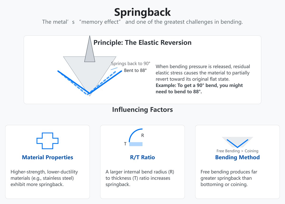
(2) Springback
The metal’s “memory effect” and one of the greatest challenges in bending.
1)Principle: When bending pressure is released, residual elastic stress causes the material to partially revert toward its original flat state. For instance, achieving a true 90° bend might require bending to 88°.
2)Factors: Springback is not fixed. Higher-strength, lower-ductility materials (like stainless steel or high-strength steel) exhibit more springback; a larger internal bend radius-to-thickness ratio (R/T) also increases it; and free bending produces far greater springback than bottoming or coining.
(3) Compensation strategies
Modern CNC press brakes often include material databases and algorithms to automatically apply over-bend compensation. For high-precision parts, trial bends and manual adjustments are still essential. Mastering springback prediction is a defining skill separating average operators from expert technicians.
(4) Grain direction
A subtle detail that can cause catastrophic failures if overlooked.
1)Principle: During rolling, a sheet’s crystalline structure elongates along the rolling direction, creating a “grain” similar to wood. Ductility is reduced in that direction.
2)Golden rule: Whenever possible, bend across the grain (perpendicular to the rolling direction). Bending parallel to the grain—especially with small bend radii—drastically increases the risk of surface cracking. Proper nesting plans should account for grain direction from the outset to ensure structural integrity.
Ⅳ. Tooling: The art of matching punches and dies
If the press brake is the body’s strength, then tooling is the skillful hands that shape its soul. The precise pairing of punch and die transforms cold, unyielding sheet metal into intricate, high-precision components. Choosing and matching tooling is far more than consulting a chart—it’s a craft blending mechanics, geometry, and seasoned judgment. The wrong combination can lead to cracking, dimensional inaccuracy, or tool damage, while the right pairing paves the way to high-speed, precise, waste-free production.

1. Understanding punch terminology
The punch is the active, male component that drives into the material. Its geometry defines the inner bend profile and determines clearance in complex forming operations.
(1) Punch angle and tip radius (sharp, standard, large-radius)
1)Punch angle:
A counterintuitive but critical parameter. To achieve a precise 90° bend, we often use punches with angles of 88°, 85°, or even sharper. This deliberate “angle allowance” counters material springback in free bending, and in bottoming or coining must match the die’s angle to lock in the final bend.
2)Tip radius:
The rounded edge at the punch’s leading tip is a crucial factor in stress distribution at the bend root.
Sharp/small-radius punches
When the tip radius is far smaller than the material thickness, it acts like a cutting blade, concentrating stress at the inner bend. This greatly increases the risk of tearing, especially in low-ductility high-strength steels or certain aluminum alloys—it’s a case of “cutting” rather than “guiding” the material.
Standard-radius punches
The industry’s ideal is a tip radius approximately equal to, or slightly greater than, the material thickness (1T). This produces a balanced stress distribution—compression on the inside, tension on the outside—leading to stable bending with more predictable springback.
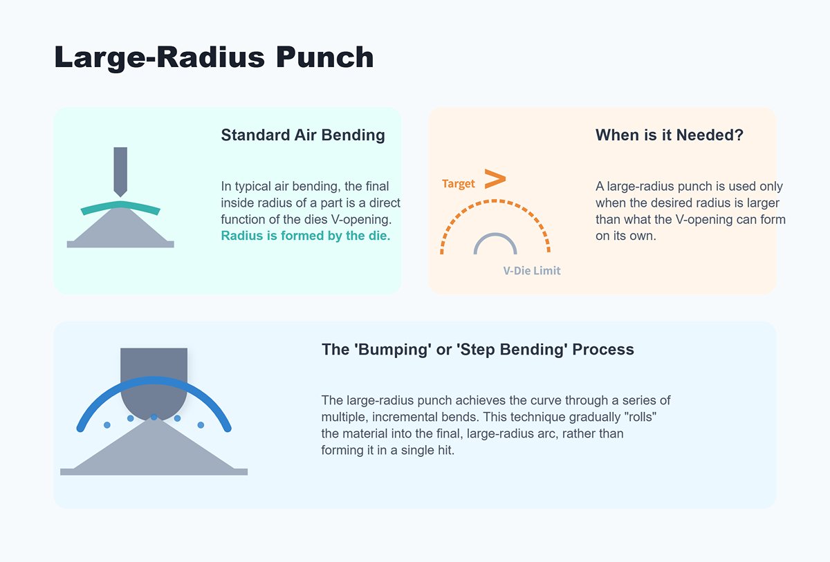
Large-Radius Punch
Designed specifically for producing parts with generous radii. It’s important to note that in air bending, the final inside radius is primarily determined by the die’s V-opening.
A large-radius punch becomes necessary only when the target radius exceeds what the V-opening can naturally form. In such cases, the desired curve is achieved through multiple bends—known as bumping or step bending—gradually “rolling” the material into the required arc.
(2) Straight Punch, Gooseneck Punch, and Specialized Forming Tools
1)Straight Punch:
A simple, linear design that is the go-to tool for basic bending operations without interference—akin to the trusty standard screwdriver in a tool kit.
2)Gooseneck Punch:
Recognizable by its recessed “gooseneck” contour, this tool is purpose-built to address clearance issues. When forming U-channels or return flanges, parts already shaped will often collide with a straight punch. The gooseneck’s stepped-back profile provides critical clearance, allowing complex geometries to be formed without obstruction.
3)Specialized Forming Tools:
This category includes beading tools, hemming dies, and louver dies, among others. These go beyond simple bends, enabling specific functional shapes to be achieved in a single press cycle.
(2) Tool Clamping Systems (American, European, etc.)
This defines how the punch connects to the press brake ram—a handshake that impacts tool-change speed, precision, and operator safety.
1)American Style:
Uses a central locating tang and bolts for secure attachment. While robust, manual alignment can be time-consuming, and the style has declined in favor of faster production standards.
2)European Style:
Employs precision alignment grooves with quick clamping mechanisms (manual, pneumatic, or hydraulic) for tool insertion, auto-alignment, and locking. It reduces tool-change time from tens of minutes to mere minutes—or even seconds—and is the standard on modern precision, high-efficiency press brakes.
2. Die Terminology Explained
The die, serving as the “female” element that supports the material, owes its importance to the geometry of its V-opening. This largely determines the bend’s outer contour, required tonnage, and ultimately, the success of the process.
(1) V-Opening: The Key Die Parameter
This is the straight-line distance between the shoulders of the V-groove. Selecting the V-opening is the first—and most critical—decision when setting up a press brake. Like the fulcrum of a lever, it directly affects:
1)Inside Bend Radius:
In air bending, the inside radius comes naturally from the V-opening, not the punch. For mild steel, the inside radius is roughly 15%–17% of the V-opening width. By switching dies with different openings, you can precisely control the finished inside radius.
2)Required Tonnage:
A wider V-opening acts like a longer lever arm, reducing the force needed for bending. Narrow openings, conversely, increase tonnage demands exponentially. Choosing the right V-opening is fundamental to preventing overload and safeguarding equipment.
(2) Die Angle and Shoulder Radius
1)Die Angle:
Typically sharp, such as 88° or 85°, to suit air bending and to leave space for springback.
2)Shoulder Radius:
The rounded edge at each side of the V-opening. This seemingly small detail protects the material’s surface. Sharp shoulders can leave pronounced marks or even scratch coatings. For high-finish materials like stainless steel, aluminum, or pre-coated sheet, a larger shoulder radius is crucial.

(2) Single-V, Double-V, and Multi-V Dies
1)Single-V Die:
The simplest form—one die body with a single V-opening.
2)Double-V/Multi-V Dies:
Designed for efficiency, these dies have multiple V-openings machined into different faces of a block. For example, a four-way die block offers four distinct openings.
Operators can rotate or flip the block for quick changes between operations, significantly reducing search, handling, and installation time—a productivity booster for high-mix, low-volume runs.
3. The Golden Rules for Matching Punch and Die
Theory should serve practice. Below are time-tested rules, verified in workshops worldwide, to ensure optimal bending quality and efficiency.
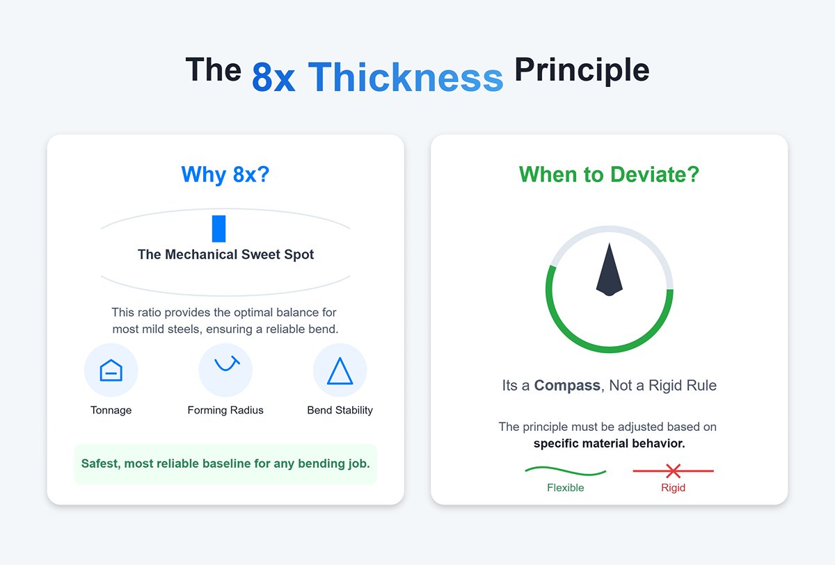
(1) The “8× Thickness” Principle: The Universal Starting Point for V-Opening Selection
This is the most famous and fundamental guideline in press brake work: “V-opening width should be roughly eight times the material thickness.”
1)Why 8×?
This ratio hits the mechanical sweet spot for most mild steels, balancing tonnage, forming radius, and bend stability. It’s the safest, most reliable baseline for any bending job.
2)When to Deviate?
This is not a rigid rule but a compass that must be adjusted for material behavior:
Soft Materials (e.g., soft aluminum)
Can be reduced to 6× thickness for a tighter inside bend radius.
Hard Materials (e.g., stainless steel, high-strength steel)
With lower ductility, require wider openings (10×–12× thickness) to give the outer layer ample stretch space, distribute stress, and prevent cracking.
Thick Plate (>10 mm)
Should also use factors above 8× (10×–12×) to lower tonnage requirements and ensure safe forming.
(2) The “Danger Zone” Below 5×
Under no circumstances should the V-opening be narrower than five times the material thickness. In such cases, the punch acts more like a wedge, cutting into the material rather than bending it—this risks both part failure and irreparable die damage.
1)Matching Punch Tip Radius to Material Properties to Prevent Outer Corner Cracking
Every material has a physical limit—the Minimum Bend Radius. Bending tighter than this causes the outer fibers to tear under excessive tension.
The selected punch tip radius must never be smaller than the material’s minimum bend radius. Always check the material datasheet during programming or design to confirm the inside radius stays within formable limits. Attempting to bend a material rated at 2 mm minimum radius with a punch tip of 0.2 mm is a guaranteed recipe for cracks.
2)Segmented vs. Full-Length Dies: Pros and Cons
Full-Length Die: Best suited to mass production of a single part type. The advantage lies in rigidity, ensuring consistent angles along long workpieces. The drawback is weight and lack of flexibility.
3)Segmented Dies
These involve cutting a long die into a set of standard-length segments (e.g., 10, 20, 50, 100 mm). Their key strength lies in unmatched flexibility; operators can assemble any required length as if building with blocks, easily leaving a “gap” in the middle for boxes or complex shapes to avoid interference. For modern sheet metal fabrication involving varied products and small batches, segmented dies are a top choice for boosting responsiveness and reducing overall costs.
Quick Reference Table for Material Thickness vs. Recommended V-Opening
| Material Thickness (mm) | Recommended V-Opening (mm) | Estimated Internal Bend Radius (mm) | Minimum Flange Length (mm) |
|---|---|---|---|
| 1.0 | 8 | ~1.2 - 1.4 | ~5.5 |
| 1.5 | 12 | ~1.8 - 2.0 | ~8.5 |
| 2.0 | 16 | ~2.4 - 2.7 | ~11.0 |
| 3.0 | 25 | ~3.7 - 4.2 | ~17.5 |
| 5.0 | 40 | ~6.0 - 6.8 | ~28.0 |
| 8.0 | 63 | ~9.5 - 10.7 | ~44.0 |
| 10.0 | 80 | ~12.0 - 13.6 | ~56.0 |
Note: This table is based on low-carbon steel (~450 MPa tensile strength). For stainless steel, increase the V-opening by 50%; for soft aluminum, reduce it by 25%. The minimum flange length refers to the smallest size that can stably rest on the V-die shoulders—typically around 70% of the V-opening width.
Ⅴ. Bending Process Methodology: Three Core Techniques and Special Applications
Choosing a bending method on a press brake is not a simple binary decision—it’s a strategic balance of cost, efficiency, and precision. The choice affects tonnage consumption, die life, and whether the final product meets tight design tolerances. Modern CNC (Computer Numerical Control) technology has transformed this decision-making process, turning what once relied on seasoned craftsmen’s intuition into a precise, accessible science. Mastering the three core techniques and their specialized variants is your path from simply following instructions to proactively optimizing production.
1. Air Bending: The Most Flexible and Common Method
Air bending dominates today’s sheet metal shops, perfectly complementing CNC press brake performance and efficiency. The term describes its physical nature: during bending, most of the sheet remains “in the air,” unsupported by the die.
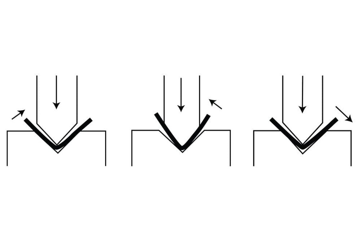
(1) Principle: Three-point contact, angle set by Y-axis depth
In air bending, the sheet touches only three points: the punch tip and the two shoulders of the V-die. The punch presses the sheet into the V-opening but never bottoms out. The angle is determined entirely by how deeply the punch (Y-axis) penetrates the die. The deeper the press, the sharper the angle—like bending a stiff card with three fingers, where the middle finger’s downward pressure sets the bend precisely.
(2) Advantages: Low tonnage requirements, high die versatility
1)Low tonnage consumption:
Thanks to leverage and the fact that the punch doesn’t need to compress the material fully, air bending uses the least tonnage of the three methods. This allows smaller-capacity machines to handle tasks, lowering energy use and minimizing wear on both machine and tooling—making it a smart choice for sustainable production. Learn more about how this makes air bending ideal for efficient metalwork in Air Bending: Precision Sheet Metal.
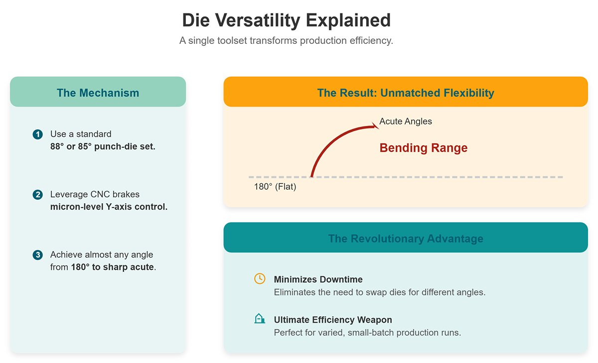
2)Die versatility:
Perhaps its most revolutionary advantage. A standard 88° or 85° punch-die set can, through micron-level Y-axis control on a CNC brake, bend almost any angle from 180° to sharp acute angles. This minimizes downtime needed to swap dies for different angles, making it the ultimate efficiency weapon for varied, small-batch production.
(3) Challenge: Springback compensation is critical
Because the material isn’t “locked in” at the bend, its natural elastic recovery (springback) is most pronounced in air bending—once its biggest technical hurdle.
Modern CNC press brakes tackle this through built-in material databases and predictive algorithms that calculate springback for different materials, thicknesses, and radii, then apply “over-bending” (e.g., bending to 88° to let it spring back to 90°) for precision results. CNC has elevated air bending from an experience-based craft to a universally controllable science.
2. Bottoming: Improving Precision and Consistency
Bottoming bridges the gap between the flexibility of air bending and the extreme precision of coining. It aims to increase accuracy and repeatability while avoiding the massive tonnage demands of coining.
(1) Principle: Punch tip lightly presses into material base
In bottoming, the punch drives the sheet deeper into the V-die until the sheet’s inside radius fully matches the punch radius, and the outside surface closely fits the V-die’s sloping faces. Critically, the punch radius is imprinted into the workpiece, defining the internal bend radius. To offset residual springback, die angles are often slightly sharper than the target angle (e.g., using an 88° die to deliver a 90° bend).
(2) Advantages: Reduced springback, higher angle precision
By applying extra pressure at the bend’s root and slightly compressing the metal’s crystalline structure, bottoming can significantly cut springback, yielding higher consistency and precision than air bending. Before CNC technology, this was the primary method for achieving precise angles.
(3) Tonnage demand: Typically 3–5× that of air bending
While less extreme than coining, bottoming still requires far more tonnage than air bending—about three to five times more. This means higher energy consumption and faster die wear. Since CNC air bending now meets precision needs in over 95% of cases, bottoming’s use has greatly declined.
3. Coining: The Ultimate Zero-Springback Technique
Coining lives up to its name, resembling the minting of a coin—it uses extreme pressure to transfer the die’s exact geometry flawlessly onto the workpiece.
(1) Principle: Fully penetrate and permanently deform the material
In coining, the punch forces the sheet entirely into the lower die with enough tonnage to cause plastic flow in the metal’s crystalline structure, filling every gap between the punch and die. In the bend zone, the material is slightly thinned. The workpiece is effectively “cast” against the die, with the final angle precisely defined by the die itself.
(2) Advantages: Extreme angle precision, virtually no springback
Since the stress applied vastly exceeds the yield strength, elastic recovery is eliminated. The finished angle exactly matches the die angle, making coining the ultimate method for highest accuracy and consistency.
(3) Challenge: Enormous tonnage requirements (5–8 times greater), severe wear on tooling and machinery
The tonnage needed for coining is typically five to eight times that of air bending, and sometimes even higher. This places extremely demanding requirements on the press brake’s rigidity and the strength of the tooling. The immense stresses dramatically accelerate wear and damage to both the machine and the dies.
As a result, in modern production, coining has become rare due to its high cost, employed only in exceptional cases where extreme angular precision is required and cannot be achieved by other means. It’s more akin to a “nuclear option” in forming — reserved for special situations rather than everyday use.
4. Specialized Bending Terminology
Beyond the three fundamental methods above, bending includes a repertoire of inventive techniques designed to achieve specific geometries.
(1) Hemming
Hemming folds and flattens the edge of a sheet back onto itself, usually in two steps: first, a sharp-angled bend to about 30° using an acute die, then a change to a flat hemming die to press it closed. The main goals are to remove sharp edges, increase edge rigidity, and improve appearance.
1)Closed Hem
The edge is fully flattened so it lies flush against the sheet. This is the most common type. Due to the severe deformation at the fold line, it’s unsuitable for materials with poor ductility (such as many aluminum alloys or high-strength steels), as it can cause cracking.
2)Teardrop Hem
The folded edge retains a small, teardrop-shaped gap rather than being crushed completely. This gives the material some “breathing room” during bending, making it a safe choice for brittle materials like aluminum.
3)Open Hem
The hem is flattened but leaves a noticeable gap at the crease, often used when another sheet needs to be inserted or when the hem serves as a handle.
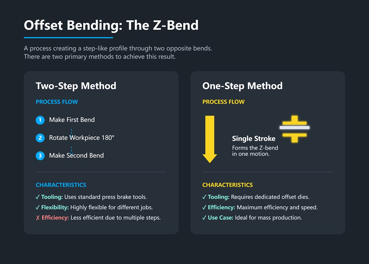
(2) Offset Bending / Z-Bends
Creates two bends of opposite angles in one or two strokes, resulting in a step-like or “Z” shaped profile.
1)Two-Step Method: Using standard tooling, make the first bend, then rotate the workpiece 180° to make the second. Highly flexible but less efficient.
2)One-Step Method: Uses dedicated offset tools with steps on both upper and lower dies to form the Z-bend in a single stroke, offering maximum efficiency and making it ideal for mass production.
(2) Radius Bending
Required when the desired internal bend radius is much larger than what air bending can naturally produce.
(3) Large-Radius Punch
The simplest approach is to use an upper die with the target radius, suitable for applications requiring very high precision and surface quality on the curve.
(4) Step Bending / Bumping
A flexible, widely used “trick” in which an operator uses a standard sharp punch to create a series of small, shallow bends that gradually approximate a large radius. With CNC programming to precisely control the step spacing and depth of each press, it’s possible to recreate virtually any radius or complex curve—showcasing the exceptional computational and motion accuracy of modern CNC press brakes.
IV. Conclusion
Our passage mainly talks about the basic concept of the press brake and relevant terminologies, which may assist you in mastering industry knowledge.
For a deeper understanding of our machine specifications and capabilities, we invite you to download our product brochures. Should you have any specific questions or require a tailored solution for your project, please feel free to contact us.
V. FAQs
1. How is the rule of 8 applied in press brake operations?
The rule of 8 refers to the practice of maintaining a minimum die opening that is eight times the thickness of the metal being bent. This ensures accurate bending and prevents damage to both the material and the machine.
2. Which techniques are essential for effective bending machine usage?
Effective usage involves techniques like calculating the bend allowance, establishing appropriate back gauge positions, and selecting the right dies for specific bends. Operators must understand material properties and machine limitations to achieve desired outcomes.
3. What are the key components involved in a brake press system?
Key components include the upper beam (ram), lower beam (die holder), back gauges for positioning material, and control systems for managing operations. The entire system must work in harmony to produce precise bends.


