I. Introduction
In the world of sheet metal fabrication, understanding the concept of sheet metal setbacks is crucial for achieving precise bends and high-quality results. This guide will delve into the definition of sheet metal setback, its calculation methods, and related terms, providing you with the knowledge needed to excel in your metalworking projects.
II. What Is Sheet Metal Setback?
1. Definition of setback
Before understanding the sheet metal setback, it is important to be familiar with the definitions of the mould line and bend line:
- The bend line refers to the straight line present on both sides of the bend plates and is located at the intersection of the bend area and the flange edge.
- The mold line refers to the straight line formed at the intersection of the outer surfaces of two bent flanges and can be either an outside or inside mold line.

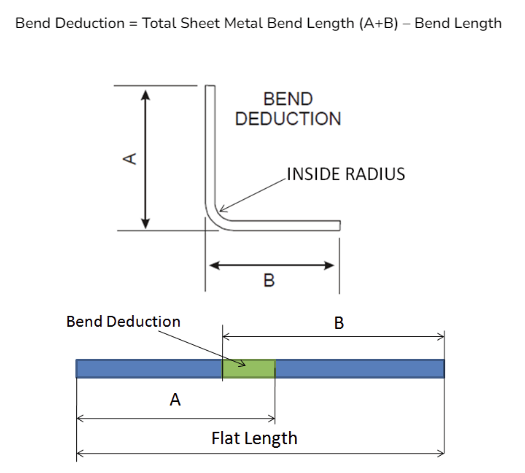
Sheet metal setback refers to the distance from the bend line to the point where the metal starts to bend. It is also described as the difference between the mold line length and the flange length. Also is a crucial factor in sheet metal fabrication. In a 90-degree bend, the setback value is equal to the bend radius plus the thickness of the metal sheet.
To make this less abstract, let’s visualize a cross-section of a finished bent part:
- Imaginary Intersection Point: Imagine extending the outer surfaces of two bent planes infinitely—they will meet at a theoretical sharp point. While this point does not exist physically, in drawings and calculations, it serves as the reference origin for all external dimension measurements.
- Tangent Point: This is where the arc of the bend meets and is tangential to the straight flange. In other words, it is the precise boundary where the "straight" ends and the "bend" begins.
- Setback: The distance measured from that "imaginary sharp point," along the outer flange surface, back to the exact point where the bend starts.
By knowing the setback size, we can determine the bending tangent position of the workpiece. The setback plays a crucial role in workpiece design. If the workpiece needs to be bent multiple times, the setback must be subtracted for each bend.
It is important to note that the bend allowance and bend deduction can change based on changes in the K factor value, but the setback remains constant regardless of changes in the K factor. The k-factor is the ratio between the thickness of the metal being bent and something called the “neutral axis/line.”
2. The High Price of Neglect
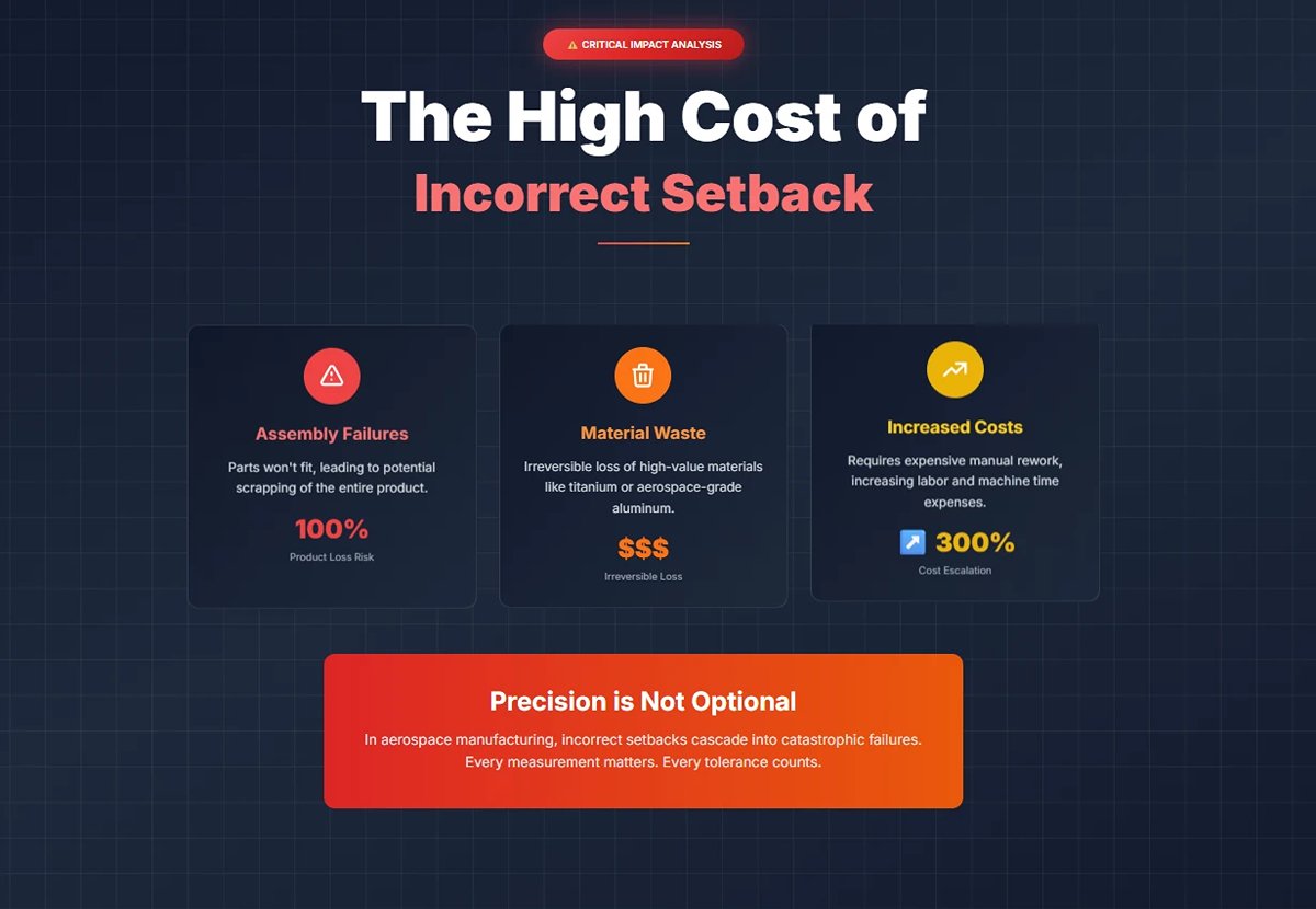
Treating setback as just another calculation parameter is often the first step toward project failure. An incorrect setback calculation can trigger a chain reaction of costly errors that go far beyond the price of a single scrapped piece.
(1)Quantifiable Impact
If the setback is wrong, bend lines will be misplaced, causing the final flange length to fall outside tolerance. The direct consequences include:
1)Dimensional Out-of-Tolerance & Assembly Failures: The part won’t fit with other components. In complex assemblies, even a minor deviation can cause the entire product to be scrapped.
2)Irreversible Material Waste: Particularly with expensive materials like stainless steel, titanium alloys, or aerospace-grade aluminum, each bending error can render a high-value sheet completely unusable.
3)Skyrocketing Secondary Processing Costs: Even small errors may require extensive manual rework, grinding, or reshaping by skilled technicians. This increases labor costs and ties up valuable machine time—an expensive double hit.
(2)Efficiency Connection: Accurate Setback is the Foundation of High Productivity
Accurate setback calculations are directly tied to First Pass Yield (FPY)—the percentage of products that meet quality standards without rework. FPY is a core metric of manufacturing efficiency.
1)Boosting FPY: A precise setback ensures the flat pattern is correct from the start, minimizing interruptions caused by rework and dramatically improving FPY.
2)Avoiding Production Bottlenecks: Reworked parts disrupt workflow, consume resources, and delay subsequent operations, lowering overall line efficiency and throughput.
3)Preventing Project Delays: In tight delivery schedules, repeated trial-and-error and rework due to bending inaccuracies are among the top causes of missed deadlines. In severe cases, they can damage client trust and brand reputation.
3. The Core Triad: Setback vs. Bend Allowance vs. Bend Deduction
Setback, bend allowance, and bend deduction are the three most fundamental—and most commonly confused—concepts in flat pattern calculation. Each serves a distinct role, but all are interrelated, ensuring precise translation from drawing to finished part.
| Characteristic | Setback (SB) | Bend Allowance (BA) | Bend Deduction (BD) |
|---|---|---|---|
| Definition | Geometric distance from the external imaginary sharp corner to the bend tangent point | Actual arc length along the neutral axis within the bend region | Length to subtract from the total measured size to obtain the correct flat length |
| Fundamental Basis | Pure geometry (IR, T, A) | Geometry + Material yield properties + K-factor | Derived from SB and BA: BD = 2×SB − BA |
| Application | Precisely locating the bend line | Added to flange lengths to get total flat length | Back-calculated from finished dimensions to determine flat length |
(2) Two Common Calculation Approaches
1)Addition Method: Measure the length from each flange to its tangent point and then add the BA. In this case, the setback is used to work back from the outer dimension to the flange’s tangent position.
2)Subtraction Method: Add the two outside dimensions together and subtract the BD to get the flat length. Since BD includes twice the SB, setback is a core variable in this formula.
Setback acts as the geometric bridge, BA quantifies the physical arc length, and BD is the simplified calculation that ties them together. If any variable is wrong, the entire dimensional chain collapses. Precision in setback is the first safeguard for seamless sheet metal design and manufacturing.
(3) How Do the Three Work Together?
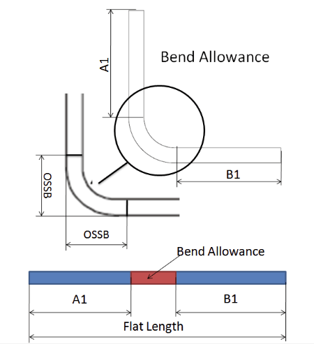
Consider calculating the flat length for a V-shaped component:
1)Addition Logic – Using Bend Allowance (BA):
Add the lengths of the two straight flanges, then include the actual developed length of the bend (BA).
Flat Length = Flange 1 Straight Segment + Flange 2 Straight Segment + Bend Allowance (BA)
Here, the role of the Setback is to subtract it from the total outside dimension, giving you the exact flat length of each flange.
2)Subtraction method – using Bend Deduction (BD):
Directly measure the combined outside lengths of the two flanges extended to their imaginary intersection point, then subtract a consolidated deduction value (BD) to account for the material “gain” during bending.
Flat length = (Outside dimension 1 + Outside dimension 2) - Bend Deduction (BD)
Setback forms the geometric reference, Bend Allowance quantifies the material’s physical change in the bend area, and Bend Deduction packages the first two into one practical, production-friendly equation.
All three are essential, together forming the theoretical foundation of accurate sheet metal flat pattern development. A deep understanding and precise calculation of Setback is the first—and most critical—step towards efficient, low-cost, high-quality sheet metal manufacturing.
III. Calculating Sheet Metal Setback
Accurate calculation of sheet metal setback requires considering several factors, including material thickness, bend radius, and bend angle.
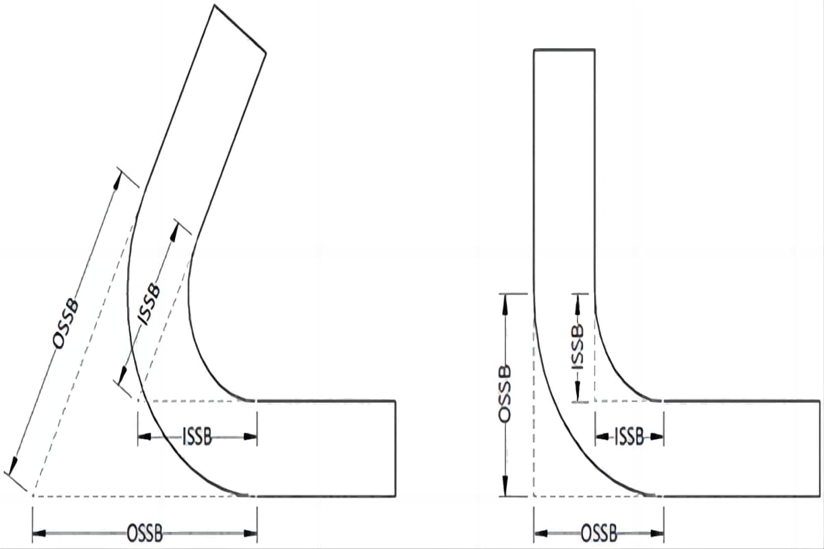
The difference between inside and outside setbacks lies in their reference points:
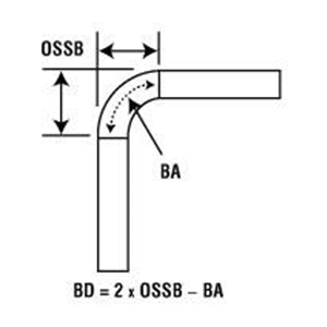
Outside Setback (OSSB) is based on the imaginary sharp corner of the outer surface, typically used in flat pattern calculations.
Inside Setback (ISSB) is based on the imaginary sharp corner of the inner surface, often used for inner cavity and mating part design.
In simple terms: OSSB defines the control skeleton; ISSB defines the control cavity.
1. Outside Setback Calculation
Outside Setback (OSSB) =Tan (A/2) × (T+R)
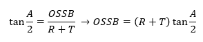
Where A is the bend angle, T is the sheet thickness, and R is the inside bend radius.
2. Inside Setback Calculation
The inside setback helps determine how far from the bend's tangent line the material starts bending on the inside of the sheet. This calculation is essential for aligning the bend with the sheet's edge and previous bends.
The above video is the setback formula. Additional factors such as the K-factor and bend allowance may need to be included in the calculation for more complex bends.
The setback is divided into two types: inside setback and outside setback. The bend angle and radius are the factors affecting the setback:
- The inside setback is the distance from the tangent point of the inside radius to the vertex of the inside mold line. Understanding the inside setback of the workpiece is an important part of designing a piece of sheet metal parts. If the bend angle and radius change, the bend line and vertex will also move.
- The outside setback is the distance from the tangent point of the radius to the outside bend vertex of the flange. By knowing the values of outside setback and bend deduction, we can obtain the bend allowance.
Examples of Setback Calculation
Example 1: Inside Setback
Consider a sheet metal with a thickness of 2 mm, a bend angle of 90 degrees, and an inside bend radius of 5 mm.
Identify the formula:
Substitute the values:
Calculate the tangent:
Apply the formula:
Example 2: Outside Setback
Identify the formula:
Substitute the values:
Calculate the tangent:
Apply the formula:
IV. Seven-Step Industrial-Grade Operating Guide
1. Step One: Verify and Input Base Data
This is the foundation for all subsequent calculations. Even the smallest error here will be exponentially magnified downstream. Before touching any machine or formula, we must be certain our input data reflects indisputable physical reality.
(1) Confirm material type and batch
Retrieve the correct material from the stockroom and locate its material test report—this serves as the part’s “birth certificate.”
(2) Measure actual thickness (T)
Using a calibrated micrometer, measure thickness at multiple points on the sheet (at least three: both ends and the center) and take the average. Never rely solely on nominal thickness.
For instance, a sheet labeled 3.00 mm thick could actually measure 2.91 mm or 3.08 mm—a difference that can be critical to your calculations.
(3) Identify target parameters
From the drawing, pinpoint two key specifications: target inside bend radius (IR) and target bend angle (A).
Even within the same grade, yield strength can vary between batches by 10–15% within standard limits.
Yield strength is directly proportional to springback, which explains why “last week’s settings worked perfectly, but not this week.” Higher-yield batches will require greater springback compensation.
2. Determine Inside Bend Radius (IR) and Select the Appropriate Tooling
This step transforms the designer’s abstract intent (the IR specified on the drawing) into a shop-floor reality using available tooling.
(1) Check minimum safe IR
Based on material type and thickness, consult process manuals or supplier data to ensure that the specified IR meets or exceeds the material’s minimum safe bend radius to avoid cracking.
(2) Select the V-die
This is both the most critical and most commonly misunderstood step. In air bending, the width of the V-die you choose determines the resulting natural IR—not a direct selection of IR itself.
(3) Select the punch
Choose a punch with a tip radius less than or equal to the target IR.
(4) The golden rule for V-die width
For low-carbon steel, the classic “8× rule” (V-die width ≈ 8 × material thickness T) is a solid starting point, but not a universal truth.
- Soft aluminum (5052): V-die width ≈ 6 × T
- Stainless steel (304): V-die width ≈ 10 × T
- Advanced high-strength steel (AHSS): V-die width ≈ 10–12 × T or greater

(5) How does V-die width determine IR?
IR ≈ 15–20% of the V-die width.
For example, with 3 mm low-carbon steel and a V-die width of 24 mm, you’ll get a natural IR of roughly 3.6 mm.
If you aim for an IR of 1.5 mm, achieving it with a 24 mm V-die is virtually impossible—you need a narrower die (e.g., 12 mm). Recognizing this is a major leap from amateur to professional-level bending.
3. Pinpoint the Dynamic K-factor
Say goodbye to generic charts—find the true K-factor for your specific conditions. A K-factor isn’t “looked up”; it’s validated.
(1) Primary source: in-house database
Based on the confirmed material, measured thickness (T), and approximate IR/T ratio, consult your in-house process database for a verified starting value.
(2) Secondary source: reputable charts
If no internal data is available, refer to tables from equipment or tooling manufacturers (e.g., TRUMPF, Bystronic) for an initial value. you can also review the specifications of our advanced machinery in our Brochures.
Common Material K-Factor Quick Reference Range:
| Material Type | IR/T Ratio | K-Factor Range | Professional Insight |
| Soft Aluminum (e.g., 5052) | < 1 | 0.33 - 0.40 | Soft material; the neutral axis compresses and flows inward with ease. |
| 1 - 3 | 0.40 - 0.45 | ||
| Low Carbon Steel (e.g., A36) | < 1 | 0.40 - 0.44 | Moderate hardness; inward shift of the neutral axis is less than that of aluminum. |
| 1 - 3 | 0.44 - 0.48 | ||
| Stainless Steel (e.g., 304) | < 1 | 0.42 - 0.46 | High hardness; pronounced work hardening and strong resistance to compression. |
| 1 - 3 | 0.46 - 0.50 | ||
| General Physical Principles | IR >T (large bend radius) | → 0.50 | Deformation is gradual; tension and compression are nearly symmetrical, and the neutral axis returns to the physical center. |
| IR ≈ 0 (sharp bend) | → 0.33 | The inner layer is highly compressed, forcing the neutral axis to its extreme inward position. |
(3) How to build your own K-factor database
1)Precisely cut a test coupon (e.g., 50 mm × 150 mm).
2)Using the die selected in Step 2, bend it precisely to 90° (verify repeatedly with a high-precision digital protractor).
3)Accurately measure the lengths of both flanges, L1 and L2, the actual inside radius IR using a radius gauge, and the material thickness T.
4)Calculate the actual Bend Deduction (BD):
BD-actual = L1 + L2 − 150.
5)Now reverse-calculate the K-Factor. We know that BD = 2(IR + T) − BA (for a 90° bend), and BA = (π/2) × (IR + K × T). By substituting BD_actual, you can backsolve for the optimal K-Factor for the current [material + thickness + tooling] combination.
6)Record this K-Factor for future reference.
4. Execute the Core Formula Calculations
This step is where you translate physical parameters into numerical values that the machine can interpret—systematically, rigorously, and without missing any detail.
Using the actual values you’ve confirmed and calculated, plug them into the flat length formula. The most efficient approach is to compute the Bend Deduction.
(1) Calculate the Bend Allowance (BA)
BA = A × (π/180) × (IR + K × T)
This represents the true arc length along the neutral axis in the bend region.
(2) Calculate the Outside Setback (OSSB / Setback)
OSSB = tan(A/2) × (IR + T)
This is the geometric distance from the virtual sharp corner to the tangent point.
(3) Calculate the Bend Deduction (BD)
BD = 2 × OSSB − BA
This is the correction value that needs to be subtracted from the ideal total length.
(4) Calculate the Final Flat Length:
Flat Length = (Outer Flange 1 Length + Outer Flange 2 Length) − BD
Modern CAD/CAM software can run these calculations automatically, but you must ensure that the “sheet metal rules” in your software contain your own measured and calculated T, IR, and K-Factor—not just the generic defaults, which may be far from your shop’s real-world conditions.

When reality doesn’t match the simulation, understanding these formulas lets you pinpoint exactly which parameter in CAD to check, instead of randomly tweaking machine settings. The formulas are your diagnostic tool. For a comprehensive guide that delves deeper into these calculations, explore our K-Factor Bend Allowance and Bend Deduction Precise Solutions.
5. Anticipate and Compensate for Springback
Here, we’re tackling metal’s “memory” head-on—using physics to “trick” it so that it springs back precisely into the position we want.
(1) Look Up Springback Data
Based on the material’s yield strength and IR/T ratio, consult your springback database or reference charts to find the estimated springback angle.
(2) Apply Overbending
Set an “overbend” angle in the press brake’s CNC system.
Programmed Angle = Target Angle − Estimated Springback Angle.
For example, if the target is 90° and the estimated springback is 2°, you should program a bend to 88°.
High-end press brakes are equipped with real-time angle measurement systems. Using lasers or small contact probes, they measure the bend angle during forming and automatically adjust the punch’s depth based on live feedback, ensuring the exact target angle is achieved.
This nearly eliminates reliance on springback charts, dramatically increasing first-piece success rates and consistency—especially when working with costly materials or high-strength steel.
Springback is not a constant; even on the same part, the first bend and second bend may have different springback values because work hardening from the first bend alters the material’s behavior in the second. This is especially noticeable in U-channel forming, requiring slightly different compensation for the second bend.
6. First Article Inspection (FAI)
(1) Produce the First Piece
Manufacture the first sample strictly according to the set parameters.
(2) Thorough Measurement
Use calibrated measuring tools (high-precision digital protractor, caliper, height gauge, radius gauge) to measure all aspects of the part.
If the dimensions are off, don’t adjust blindly. Follow this diagnostic sequence:
1)First, check the angle: If the angle is wrong, your springback compensation (Step 5) is off. Adjust the programmed angle and try bending again. Don’t touch dimensions until the angle is correct.
2)Next, check flange dimensions: If the angle is correct but flange lengths are off, your flat length calculation is likely wrong—often due to an inaccurate K-Factor (Step 3). Go back to Step 3 to back-calculate and correct the K-Factor.
3)Finally, check the actual IR: Use a radius gauge to measure the formed inside radius. Does it match your expected IR (as determined by the V-die)? If not, your assumption about the tooling-to-IR relationship may be off—which in turn affects both the K-Factor and springback.
7. Record, Optimize, and Standardize
(1) Structured Recordkeeping
Thoroughly document all successful final parameters from the trial run in your process database, linking them to the specific part number, material batch, and equipment/tooling used.
(2) What to Record
Must include: actual sheet thickness, top/bottom die model numbers, final programmed angle, measured springback value, and the precisely back-calculated K-Factor.
This database is one of the company’s most valuable assets—it quantifies and preserves the “feel” and craftsmanship of experienced operators.
Taking it further, this structured data can form the foundation for integrating a Manufacturing Execution System (MES) or even machine learning optimization. With a large historical dataset, the system can automatically recommend optimal starting parameters for new parts, cutting setup time from tens of minutes to just a few.
By rigorously following these seven steps, you transform bending from an intuition-driven craft into a fully manageable, optimizable, and transferable engineering science.
V. Factors Affecting Sheet Metal Springback
Before diving into the factors that influence sheet metal springback, we must clarify two core concepts:
(1) Neutral Axis
During bending, the material’s outer surface is stretched while the inner surface is compressed. Theoretically, there’s a transitional layer that experiences neither stretching nor compression—this is the neutral axis. Its location in flat length calculations is defined by the K-Factor.
K-Factor = Distance from neutral axis to inside surface (t) / Material thickness (T).

(2) Springback
Metal has elastic memory. Once bending pressure is released, the material tries to return to its original shape, causing the final angle to be smaller than the tool angle. This is a universal challenge in bending processes that must be understood and compensated for.
Now, let’s examine the factors that affect sheet metal springback:
1. Material Properties
Material properties act as the “genetic code” of the bending process—they determine the baseline difficulty and the fundamental rules of the game.
(1) Yield Strength & Elastic Modulus
Together, these two parameters determine how much force is needed to bend a material and how much it will “spring back.”
Elastic modulus represents the material’s stiffness or resistance to deformation. The higher the modulus, the more the material resists bending, and the stronger its tendency to snap back once the force is removed—meaning greater springback.
This explains why stainless steel (with an elastic modulus of about 200 GPa) exhibits significantly more springback than aluminum alloys (around 70 GPa).
Yield strength marks the point between elastic and plastic deformation (permanent change). The higher the yield strength, the greater the stress needed to cause permanent shape change—and the greater the springback. This is the root of the challenge when bending modern Advanced High Strength Steels (AHSS).
(2) Ductility
Usually measured by elongation percentage, ductility indicates how far a material can be stretched before it fractures.
Ductility directly defines the bending limits of a material. On the outer side of a bend, the material is stretched; if this elongation exceeds the material's ductility threshold, cracks will form. This leads to a counterintuitive but crucial fact: for any given material, there is a minimum bend inner radius. Attempting a bend tighter than this radius will inevitably cause fracture.
(3) K-Factor
Softer, more ductile materials—such as soft aluminum—compress and flow more readily on the inside of a bend, allowing the neutral axis to shift inward. This results in a smaller K-factor (typically around 0.33–0.40).
In contrast, harder, high‑strength materials—like high‑strength steel—offer similar resistance to deformation in both tension and compression. As a result, the neutral axis tends to remain near the material’s mid‑thickness, giving a higher K‑factor (close to 0.5).

(4) Springback
Yield strength and elastic springback are almost directly proportional. The higher the strength of a material, the greater the portion of total deformation that remains in the elastic range—resulting in more pronounced and less predictable springback.
2. Geometric Parameters
(1) Inner Bend Radius (IR) to Material Thickness (T) Ratio (IR/T Ratio)
This is not just a simple measurement—it is the primary factor driving the mechanics of bending. It determines the severity of the deformation.
A small IR/T ratio (sharp bends, e.g., IR/T < 1) forces the material to undergo intense plastic deformation in a very confined space. This creates extremely high tensile stress concentrations in the outer fibers—often the direct cause of cracking.
At the same time, extreme compression on the inner layers pushes the neutral axis inward, reducing the K‑factor.
A large IR/T ratio (generous bends, e.g., IR/T > 5) produces more gradual deformation and more evenly distributed stress. However, much of this deformation occurs within the elastic range, meaning springback becomes more significant and harder to control.
In this case, the neutral axis lies very close to the physical center of the material, with the K‑factor approaching 0.5.
(2) Bend Angle (A)
The angle itself does not directly change the material’s properties, but it dictates the overall strain. A 120° bend undergoes more plastic deformation than a 30° bend, and thus experiences greater cumulative springback.
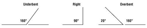
Many assume that sharper bends (small IR) are inherently harder to control. In practice, a large-radius “gentle” bend can be far more challenging, as the springback is greater and highly sensitive to even tiny variations between material batches. Achieving precision in a 160° gentle bend often demands more skill than producing a standard 90° bend.
3. Process Parameters
(1) Bending Method
This is the most critical tactical choice, as it fundamentally alters the mechanics of the process.
| Feature Comparison | Air Bending | Bottoming | Coining |
|---|---|---|---|
| Core Mechanism | Pure bending—material is stressed at three points (punch tip and both die shoulders). | Bend plus “ironing”—extra force presses the material tightly against the die to reduce springback. | "Stamping" with extremely high pressure at the bend root, forcing full plastic deformation and eliminating springback. |
| Sheet-to-Die Contact | Does not touch the bottom of the V‑die. | Inner surface nearly conforms to the bottom of the V‑die. | Punch tip penetrates the material under extreme pressure, thinning it at the bend line. |
| Angle Control | Determined precisely by punch penetration depth. | Primarily set by die geometry; penetration depth has minimal influence. | Completely defined by die geometry. |
| Springback Behavior | Most significant issue—requires precise overbending compensation. | Greatly reduced, but not entirely eliminated. | Virtually eliminated. |
| K‑Factor Relevance | Critical—forms the basis for flat pattern length and bend deduction calculations. | Partially diminished, as die geometry begins to dictate bend radius. | Not applicable—material thickness (T) is intentionally altered. |
| Required Tonnage | Low (baseline). | Higher than air bending. | Extremely high—often 5–10× that of air bending. |
| Advantages | Most versatile and widely used—one set of tooling can produce many angles. | High angle consistency and repeatability. | Exceptional precision with near-perfect repeatability. |
| Drawbacks | Angle accuracy depends on operator skill and machine control; requires careful springback compensation. | Higher tonnage needed; die angle must closely match target angle—less flexibility. | Heavy wear on tooling and materials; high cost; rarely used today. |
(2) V‑Die Opening Width
This directly affects both the bending force required and the resulting inner radius.
A wider V‑opening lengthens the lever arm, reducing the force needed—but it also allows a larger natural inner radius to form and increases springback.
The widely followed “8× thickness rule” (V‑Width ≈ 8 × T) is an industry‑tested balance between force, bend radius, and controllability.
(3) Bending Speed
An often-overlooked factor: excessive speed can generate heat, locally altering the material’s properties, and impact behavior in subtle ways due to shock effects—slightly changing springback characteristics.
4. Equipment Factors
(1) Accuracy and Repeatability
A worn hydraulic press brake may stop its ram in slightly different positions each time—micron‑level variations that can cause angular deviations of 0.1–0.5°, an unacceptable margin in precision assemblies.
Modern electro‑hydraulic servo or fully electric machines offer far superior repeatability compared to conventional hydraulics.
(2) Tooling Wear
The punch tip and die shoulders wear over time. Punch tip wear increases its radius, which in turn enlarges the actual inner bend radius (IR) and affects springback. Die shoulder wear changes the effective V‑opening width, likewise altering bend results.
This is a slow but continuous process—and a common reason why parts from the same batch may measure differently if produced days apart.
(3) Machine Deflection & Crowning Systems
Under high loads, even the most rigid machine will flex slightly like a bow—a phenomenon called deflection—causing the bend angle at the center of a long piece to be smaller than at its ends.
Modern press brakes feature crowning systems that create a controlled upward camber in the lower beam—hydraulically or mechanically—to counteract deflection. The precision and responsiveness of this system directly affect the straightness of long parts.

5. Clarifying Common Theoretical Misconceptions
(1) The Myth of a Fixed K‑Factor
The K‑factor is not a universal constant you can pull from a chart. It is a dynamic outcome determined by the combined effects of material properties (first dimension), IR/T ratio (second dimension), and bending method (third dimension). Any K‑factor table provides only a starting point for specific conditions. True experts know how to fine‑tune it for each real‑world scenario.
(2) The Overlooked Truth About Grain Direction
Metals acquire a microscopic “grain” structure during rolling.
Bending parallel to the grain (bend line along the grain) is easier, but the outer fibers at the bend are more prone to tearing—raising the likelihood of irregularities or cracks.
Bending perpendicular to the grain (bend line across the grain) requires more force but produces a more stable bend; the outer fibers can withstand greater tension, resulting in a more uniform radius and higher‑quality bends.
For critical components, the design drawings typically specify the layout direction to ensure the bend line is positioned at the optimal angle to the material grain—usually 90 degrees.
(3) Applying generic formulas without considering actual manufacturing methods
Using bend allowance or springback compensation formulas developed for "air bending" directly in "bottoming" or "coining" is entirely incorrect. Each of these three methods operates on fundamentally different principles: air bending is a matter of prediction and compensation; bottoming is about forceful forming and correction; coining is reshaping and eliminating springback altogether.
You must align the mathematical model with the manufacturing method (or strategy) you’ve chosen—otherwise, you’re chasing the impossible.
VI. Bend Allowance and Bend Deduction
1. Bend Allowance
Bend allowance is the length of the neutral axis between the bend lines, taking into account the material stretch during the bending process. The calculation formula is:
Bend Allowance = (Bend Angle × (Bend Radius + Material Thickness)) × π / 180
You can also try this Sheet Metal Bend Calculator.
2. Bend Deduction
Bend deduction is the amount subtracted from the total flat length to obtain the desired final dimensions after bending. The formula is:
Bend Deduction = 2 × (Bend Radius + Material Thickness) × tan(Bend Angle / 2)
BA (Bend Allowance) = 2 × OSSB − BD (Bend Deduction).
The outside setback can be calculated using the following formula:
The sum of the bend deduction and bend allowance is equal to twice the outside setback. This can be expressed in terms of T (sheet thickness), A (bend angle), and R (inside bend radius). For a 90° bend, the outside setback equals the bend radius plus sheet thickness.
When the bend angle is less than 90°, the complementary angle is generally used; for angles greater than 90°, either the included angle or the complementary angle is typically used.
3. Practical Bend Calculation — Example
Let’s look at a practical example. Suppose you have a sheet metal panel 2 mm thick, with a bend radius of 5 mm and a bend angle of 90 degrees. Using the formulas provided:
Outside setback: 5 mm + 2 mm = 7 mm
Bend allowance: (90 × (5 + 2)) × π / 180 = 11 mm
Bend deduction: 2 × (5 + 2) × tan(90 / 2) = 14 mm
Ⅵ. Bend Allowance and Bend Deduction
1. Bend Allowance
Bend allowance is the length of the neutral axis between the bend lines, which accounts for the material stretching during the bending process. The formula for bend allowance is:
And you can browse here to see the Sheet Metal Bending Calculator.
2. Bend Deduction
Bend deduction is the amount subtracted from the total length of the flat sheet to achieve the desired final dimensions after bending. The formula for bend deduction is:
BA(Bend Allowance)=2OSSB-BD(Bend Deduction)
The outside setback can be calculated by the following formula
The sum of bend deduction and bend allowance is equal to two times the outside setback. This can be expressed as T (sheet thickness) + A (bend angle) + R (inside bend radius). For a 90° bend angle, the setback value is equal to the bend radius plus the sheet thickness.
When the bend angle is less than 90°, the complementary angle is usually used, and when the bend angle is greater than 90°, the included angle or complementary angle is usually used.
3. Practical Calculating Bend Example
Let's consider a practical example to illustrate these concepts. Suppose you have a sheet metal piece with a thickness of 2mm, a bend radius of 5mm, and a bend angle of 90 degrees. Using the formulas provided:
Setback: 5mm+2mm=7mm
Bend Allowance:
Bend Deduction:
Ⅶ. What Is the Sheet Metal Bend Radius?
The bend radius is the distance from the bend axis to the inner surface of the sheet, generally referring to the inner radius. The value of the outside radius is equal to the inner radius plus the sheet metal thickness.
The smaller the radius, the higher the tension and compression on the material. The size of the radius is determined by the metal material's properties such as tensile strength, ductility, thickness, and the size of the die opening. As a general rule, the larger the die opening size, the larger the radius.
1. Bend Allowance Chart
2. Bend Deduction Chart
Ⅷ. Common Mistakes in Sheet Metal Setback Calculations
1. Improper Mold Design
Improper mold design is a common mistake in sheet metal setback calculations. If a mold does not align with the material's specifications or has inaccuracies, it can lead to uneven deformation during bending. This often exacerbates the springback effect, resulting in incorrect setbacks.
Ensuring that the mold design is precise and matches the material properties is crucial for achieving the desired bend accuracy.
2. Ignoring Material Properties
Disregarding material attributes such as thickness, strength, and ductility can lead to significant inaccuracies in setback calculations. These features are crucial in determining the material's behavior during bending.
For example, materials with greater tensile strength might show increased springback, requiring modifications in setback calculations. A thorough understanding and consideration of these properties are crucial for achieving accurate bending outcomes.
3. Miscalculations in Setback
Mistakes arise when the included angle isn't adjusted to its complementary angle or when the K-factor, which influences the neutral axis, is overlooked. These errors can result in inaccurate setback values. To prevent these problems, it is essential to use the correct formulas and carefully verify each step of the calculation process.
4. Neglecting the Role of Bend Radius
Selecting the appropriate bend radius, considering the material's characteristics, is essential for precise bending. The bend radius plays a critical role in influencing the tension and compression forces exerted on the material.
Opting for a smaller radius can amplify these forces, resulting in increased deformation and larger setbacks. A well-chosen bend radius ensures the precision of the final bend.
5. Overlooking Temperature and Residual Stress
The degree of springback is influenced by temperature, as it impacts the material's plasticity. Elevated temperatures generally decrease springback, enabling more accurate bending.
Moreover, residual stresses from previous processing steps can influence the final outcome. Effectively releasing these stresses is crucial for precise calculations.
6. Skipping Simulation and Experimental Data
Neglecting simulation tools and experimental data can lead to inaccurate predictions of springback and setbacks. Methods like finite element analysis (FEA) offer crucial insights into material behavior during bending, enabling more effective compensation and adjustment of setbacks.
7. Inadequate Process Control
To handle complex shapes or operations with multiple bends, precise control of the process is essential. Experienced technicians can reduce springback by adjusting process parameters, choosing suitable materials, and ensuring precise mold design. Employing advanced control measures aids in maintaining consistency and accuracy in bending operations.
Ⅸ. Designing with Setbacks
Role of Setbacks in Design Accuracy
- Avoiding Interference or Overhang in Mating Flanges or Assemblies
- Proper setback calculations ensure that mating flanges align accurately without interference or overhang, which can compromise assembly fit and functionality.
- Neglecting setbacks can result in gaps, overlaps, or misaligned parts, leading to structural weaknesses or aesthetic issues.
- Real-world example: Improperly calculated setbacks in flange designs often lead to interferences that require rework or redesign, especially in complex assemblies like enclosures or boxes.
Incorporating Tolerances
- Setting Tolerances to Account for Deviations During Production
- Tolerances define acceptable variations in dimensions to ensure parts fit together while accounting for manufacturing variability.
- Looser tolerances reduce costs but may cause alignment issues, while tighter tolerances increase precision but are costlier and harder to achieve.
- Example of tolerance stacking: In multi-bend designs, cumulative tolerances can lead to significant deviations if not managed properly.
- Best practices:
- Collaborate with fabricators early to set realistic tolerances based on manufacturing capabilities.
- Use standards like ISO 2768 or ASME Y14.5 for consistent tolerancing.
Material-Specific Considerations
- Designing Setbacks for Different Materials
- Material properties like yield strength, elasticity, and thickness influence setback requirements:
- Aluminum: High springback requires greater compensation in setback calculations.
- Steel: Lower springback but higher force requirements for bending; setbacks must account for material hardness and thickness.
- Stainless Steel: Requires stricter tolerances due to its hardness and susceptibility to deformation during bending.
- Example: Aluminum parts require larger bend radii and setbacks compared to steel to avoid cracking or excessive springback during bending.
- Material properties like yield strength, elasticity, and thickness influence setback requirements:
Examples of Design Challenges
- Real-World Issues Caused by Neglecting Setbacks
- Interference in Flange Assemblies: Ignoring setbacks leads to overlapping flanges or gaps, resulting in poor fit and additional rework during assembly.
- Tolerance Stack-Up: Without proper setback calculations, cumulative errors across multiple bends can lead to significant dimensional inaccuracies.
- Material-Specific Failures: Using the same setback values for different materials (e.g., aluminum vs. steel) can result in cracking, excessive springback, or misaligned parts.
- Solutions:
- Employ design tools like SolidWorks or AutoCAD with built-in setback calculators to predict and adjust for these challenges during the design phase.
- Use prototyping and simulation (e.g., FEA) to validate designs before production.
Ⅹ. FAQs
1. Why is sheet metal setback important in metal fabrication?
Sheet metal setback is crucial in metal fabrication because it ensures precision and accuracy in achieving the desired shape and dimensions of the final component. Proper calculation of setback helps in determining the correct positioning of bends, accounting for factors like bend angle, bend radius, and material thickness.
This is essential for compensating for springback, avoiding design issues such as interferences or poorly finished edges, and ensuring that the fabricated part meets the specified geometry and fit requirements. Understanding setback also aids in accurate bend allowance and bend deduction calculations, leading to superior fit and finish of the final product.
2. What are common mistakes in setback calculations and how to troubleshoot them?
Common mistakes in setback calculations include incorrect use of formulas, ignoring material properties, neglecting springback, and inaccurate measurements of bend angle and radius. Troubleshooting involves ensuring correct formula application, considering material properties like the K-factor, accounting for springback, and verifying measurements.
Utilizing simulation software, conducting experimental validation, reviewing design drawings, and ensuring proper training can help rectify these issues. By addressing these mistakes, fabricators can achieve precise sheet metal components, as discussed earlier in the article.
XI. Conclusion
Understanding and accurately calculating sheet metal setback is essential for precise and efficient metalworking. This blog introduces the definition, calculation method, and related terms of the setback in sheet metal bending.
The setback is a crucial aspect of workpiece design and has close connections with the k-factor in sheet metal bending, bend allowance, bend deduction, and other factors, which can help you manually modify a flat pattern to obtain the correct finished part size.
The setback is only considered in angles up to about 170 °. However, if the bend angle approaches 180°, the values of the inside and outside setbacks don't have to be considered because the setback value becomes close to infinity and the bend is nearly flat.
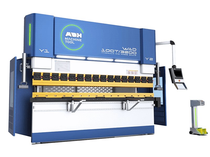
At ADH, we are dedicated to the design and manufacture of sheet metal machines, including press brakes and laser cutting machines. Contact us today for a free consultation or download our comprehensive guide on sheet metal bending to learn more.


