Press brake tooling basics are essential for accurate and efficient metal bending. Tooling, including punches and dies, shapes sheet metal and affects product quality, speed, and cost. This guide covers key tooling types, the bending principle, tool selection based on material and bend requirements, installation tips, and maintenance practices to help you achieve consistent, high-quality results.
I. Introduction
1.1 Core Definition: What is Press Brake Tooling?
At its core, press brake tooling is a matched set of components that work in concert to plastically deform sheet metal into a predetermined shape. A failure in any single component compromises the entire system.
The Primary Pair: The Punch and The Die
- The Punch (Upper Tool): Mounted to the moving ram of the press brake, the punch is the active, descending tool. Its tip, defined by its angle and radius, is responsible for forcing the material into the die and creating the inside profile of the bend. Common styles include standard straight punches, gooseneck punches (designed to navigate around previously formed flanges), and acute punches for over-bending.
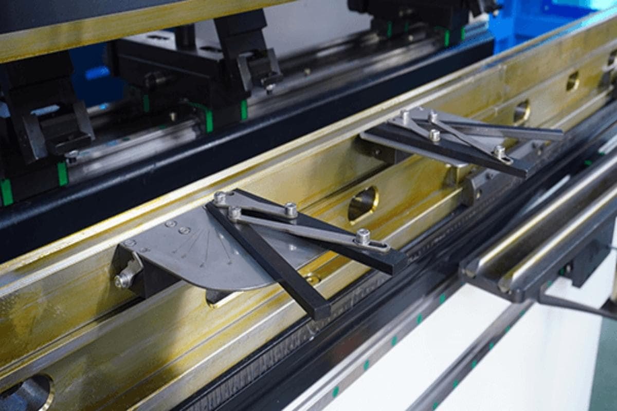
- The Die (Lower Tool): Secured to the stationary bed of the machine, the die is the foundation that supports the material and shapes its outer profile. The vast majority of bending operations use a V-Die, whose defining characteristic is the width of its V-shaped opening (V-Opening). This single dimension is one of the most critical parameters in the entire bending process.
The Support System: Clamping Systems and Holders
Often overlooked by novices but obsessed over by experts, these systems secure the punches and dies to the press brake. They are not passive components; they are the guarantors of alignment, rigidity, and speed. Modern hydraulic or pneumatic quick-clamping systems can reduce tool changeover times from over thirty minutes to under sixty seconds, directly translating to increased machine uptime and profitability.
1.2 A Simple Guide to the 'Three-Point Bend' in Air Bending
Air Bending is the most common, flexible, and energy-efficient method of forming metal on a press brake. Its principle is known as "three-point bending," and understanding it is the key to unlocking masterful control over your machine.
How 'Three-Point Contact' Shapes Metal
In air bending, the sheet metal is supported only by the two leading edges, or "shoulders," of the V-die (Points 1 & 2). The punch then descends and makes contact at the center (Point 3), forcing the material down into the V-opening. Critically, the sheet metal does not touch the bottom of the V-die. It is bent "in the air." The final bend angle is determined not by the tool's angle, but by the depth of the punch's penetration into the die. A deeper stroke creates a tighter angle, giving the operator infinite angular control with a single set of tools.
The V-Opening and Punch Radius Partnership
This is the most misunderstood relationship in basic press brake operation.
The V-Opening is the Protagonist: In air bending, the inside radius (IR) of the finished part is a direct function of the V-die opening. It is not determined by the punch tip radius. A wider V-opening will produce a larger inside radius. A reliable rule of thumb for mild steel is that the resulting inside radius will be approximately 16-17% of the V-opening width. Therefore, you "program" your radius by selecting the correct die.
The Punch Radius is the Supporting Actor: The role of the punch tip radius is primarily to ensure a healthy bend. As long as the punch radius is smaller than the naturally formed radius, it will not dictate the final dimension. However, if the punch tip is too sharp (i.e., its radius is too small relative to the material thickness), it will crease the inside of the bend, creating a high-stress point and potential fracture line. Choosing the correct punch radius is about bend quality, not bend geometry.
Understanding Springback
Springback is the unavoidable tendency of a material to partially return to its original flat shape after the bending force is released.
The Cause: During bending, the material undergoes both permanent (plastic) and temporary (elastic) deformation. When the punch retracts, the stored elastic energy is released, causing the angle to open up slightly.
Control and Compensation: The amount of springback is influenced by material type, thickness, and the bend radius-to-thickness ratio. Stronger, thicker materials spring back more. To achieve a perfect 90° final angle, a skilled operator or a modern CNC control must calculate the springback and overbend the part—for instance, bending it to 88°—so that it "springs back" to the desired 90°. Mastering this compensation is a hallmark of a true press brake professional.
II. Decoding the Tooling: A Visual Encyclopedia of Punches and Dies
2.1 The Punch (Upper Tool)
The punch is the active artist in the bending operation. Its profile dictates the inner contour of the bend and defines the boundaries of what is geometrically possible.
Classification by Profile and Clearance
- Straight Punch: This is the quintessential workhorse. With its simple, robust, and linear profile, it is designed for maximum strength and can withstand the highest tonnage pressures. It is the go-to tool for the vast majority of standard 90-degree and obtuse-angle bends, forming the bedrock of every fabricator's tooling inventory.
- Gooseneck Punch: The Gooseneck punch is the specialist, engineered to solve interference problems. Its signature recessed, "swan-neck" profile creates critical clearance, allowing the operator to form deep U-channels or parts with return flanges that would otherwise collide with a straight punch. This invaluable access comes at a cost: the geometry inherently reduces the tool's structural strength, resulting in a lower tonnage capacity compared to a straight punch of similar height.
Classification by Angle and Function
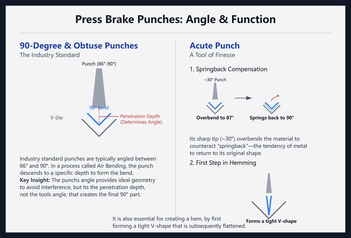
- 90-Degree and Obtuse Punches: The industry standard punch angle is typically between 86° and 90°. In Air Bending, this angle does not directly create a 90-degree part (the penetration depth does that), but it provides the ideal geometry for executing these common bends without interference.
- Acute Punch: With a sharp tip angle, often around 30°, the acute punch is a tool of finesse. Its primary purpose is not to create acute-angle parts, but to masterfully compensate for springback. By overbending the material—for instance, to 87°—it allows the metal to spring back to a perfect 90°. It is also the essential first step in creating a hem, forming a tight V-shape that is subsequently flattened.
Key Attributes at a Glance
- Height: Dictates the maximum box depth you can form. A taller punch allows for deeper flanges and channels without the workpiece colliding with the press brake's ram.
- Angle: The included angle of the punch tip. As discussed, acute angles are for overbending, while standard angles handle general work.
- Radius: The radius of the punch tip is a critical factor in bend quality. A radius that is too sharp (typically defined as less than 63% of the material thickness) will act like a knife, creating a sharp crease on the inside of the bend and increasing the risk of cracking, especially in less ductile materials. A larger radius promotes a smoother flow of material.
- Load Capacity: Expressed in tons per foot (Tons/ft) or kilonewtons per meter (kN/m), this is the absolute maximum linear force the tool can withstand. Exceeding this limit is the fastest way to permanently damage an expensive tool, compromise the press brake, and create a catastrophic safety hazard.
2.2 The Die (Lower Tool)
The die is the bedrock of the bending process. It supports the workpiece and, in air bending, is the primary variable that defines the final geometry of the part.
The Mainstay: The V-Die
- V-Opening Width: This is arguably the single most important parameter in air bending. It directly dictates both the resulting inside bend radius and the required tonnage.
- It Defines the Radius: The final inside radius of a part is a direct function of the V-opening. For mild steel, the radius will be approximately 15-17% of the V-opening width. Therefore, the operator selects the radius by selecting the die. A wider V-opening yields a larger radius.
- It Governs the Tonnage: The physics are simple: a wider V-opening creates a longer lever arm, requiring significantly less force to bend the material. Conversely, a narrower V-opening causes the required tonnage to increase exponentially. Selecting a V-opening that is too narrow for the material thickness is the most common cause of press brake overload.
Flattening/Hemming Die
Used in conjunction with a punch to complete a hem. This is a two-step process: first, an acute bend is made in a V-die; second, the punch and die are swapped for a flat flattening set, which presses the hem completely closed.
Application-Specific Dies
- U-Channel and Radius Dies: Used for bottoming or coining operations where the punch and die must perfectly match to stamp a specific shape, such as a U-channel or a large, true radius, into the part.
- Mark-Free Dies: When working with sensitive materials like stainless steel, aluminum, or pre-painted sheets, the sharp shoulders of a standard steel die can leave undesirable marks. To prevent this, two elegant solutions exist:
- Polyurethane (Urethane) Films or Dies: A durable urethane film can be placed over a standard V-die, or a solid urethane die can be used. During bending, the flexible material conforms to the workpiece, distributing the pressure evenly and creating a perfect, mark-free bend.
- Roller Dies: The shoulders of the die are replaced with hardened, rotating steel rollers. As the punch descends, the material rolls over these surfaces instead of being dragged across them. This dramatically reduces friction and is exceptionally effective at eliminating scratches and die marks, especially on thicker materials.
Key Attributes at a Glance
- V-Opening: The core parameter determining radius and tonnage.
- Angle: The included angle of the V-die should be equal to or less than the punch angle to ensure clearance during air bending.
- Shoulder Radius: The radius on the leading edges of the V-opening. A larger shoulder radius helps to distribute force and can reduce marking, but it also allows the material to sink deeper, slightly affecting the bend calculations.
2.3 Materials and Manufacturing: The Key to Tool Life and Performance
Tool Steel Selection: The Foundation of Strength and Durability
- Standard Tool Steel: Grades such as 4150 are suitable for low-load and low-output applications but lack sufficient wear resistance.
- High-Strength Alloy Steel: The industry standard 42CrMo (AISI 4140), when properly heat-treated, offers an excellent balance of hardness, toughness, and wear resistance—making it the optimal choice for most applications.
- Advanced Alloy Steel: Recommended for machining high-strength materials like stainless steel, offering superior wear and compression resistance.
Heat Treatment: Unlocking the Steel’s Potential
- Quenching and Tempering: Heating the entire part for hardening, followed by rapid cooling and tempering, results in hardness HRC 47–52—balancing strength and toughness.
- Induction Hardening: Only heats the punch tip and die shoulder surface, achieving HRC 55–60 hardness; enhances wear resistance on the surface while retaining core toughness.
- Nitriding: Introduces nitrogen atoms to form a hard layer, improving surface hardness, lubrication, and corrosion resistance.
Precision Grinding: Achieving High Accuracy
After heat treatment, precision grinding of working surfaces ensures ±0.01 mm tolerance and a smooth finish. When segmented tools are assembled, they form a perfect straight line, guaranteeing bending accuracy and consistency.
III. A 5-Step Method to Select the Perfect Press Brake Tooling
3.1 Step One: Material Analysis
This is a non-negotiable starting point. Every subsequent decision stems from a thorough understanding of the material being processed. The fundamental properties of a metal dictate how it behaves physically during bending.
Identify the material type: Different metals have entirely distinct “personalities.”
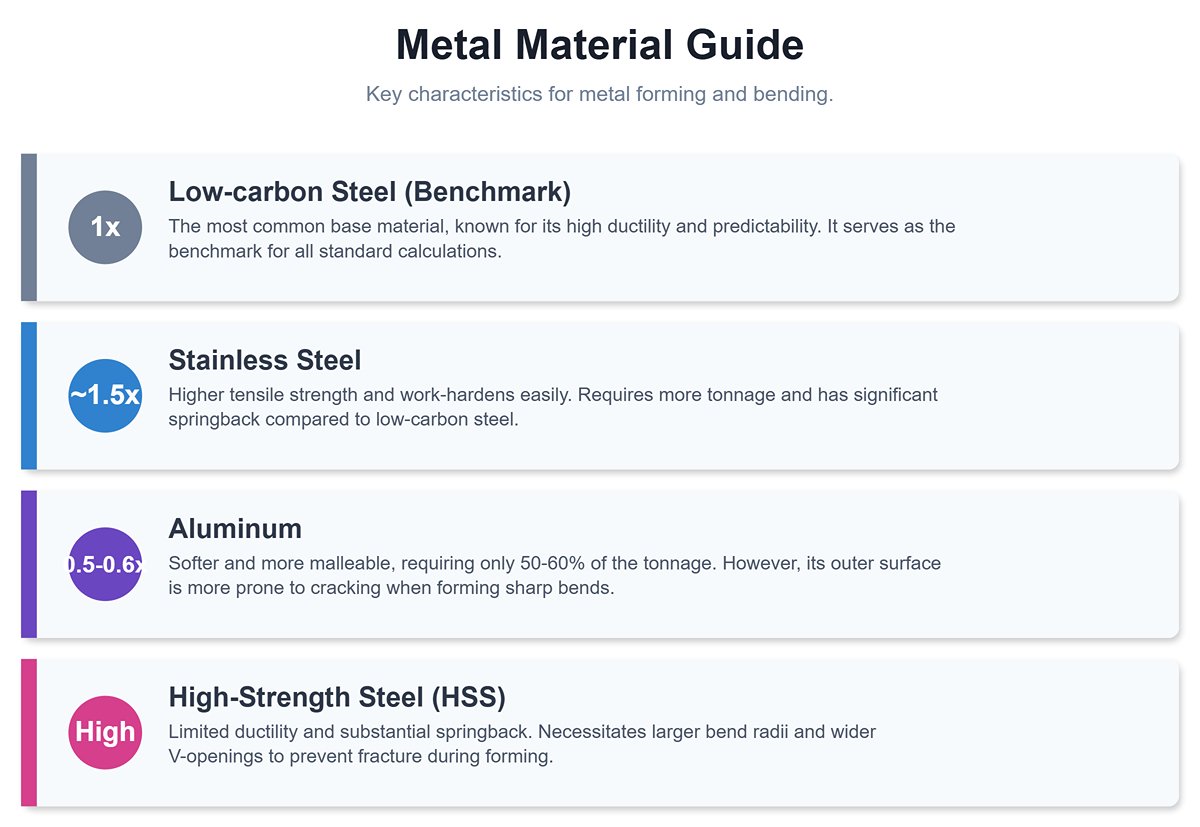
- Low-carbon steel: The most common base material, known for its high ductility and predictability. It serves as the benchmark for all standard calculations.
- Stainless steel: Possesses higher tensile strength and tends to work-harden easily. Typically requires about 1.5 times the tonnage of low-carbon steel, with significantly greater springback.
- Aluminum: Softer and more malleable, requiring only about 50–60% of the tonnage used for low-carbon steel. However, its outer surface is more prone to cracking when forming sharp bends.
- High-strength steel (HSS): This class of advanced materials has limited ductility and substantial springback, necessitating larger bend radii and wider V-openings to prevent fracture.
Verify material thickness (T) and tensile strength: These two parameters must be measured with precision.
- Thickness (T): Never rely solely on nominal values. Always measure with a calibrated micrometer to obtain the actual thickness. In tonnage calculation, thickness has a squared effect—small errors will be exponentially amplified.
- Tensile strength: This value directly determines the force required for deformation. The higher the tensile strength, the greater the tonnage needed.
3.2 Step 2: Define the Target Bend
With the material understood, you must now clarify the exact geometry you wish to create. This is the crucial step that translates the engineering drawing into a physical reality.
- Determine the Final Bend Angle (Internal): Are you forming a 90-degree angle, a 135-degree obtuse angle, or something else entirely? This will influence your choice of punch, particularly whether an acute tool is needed for overbending to compensate for springback.
- Specify the Required Inside Radius (IR): The inside radius is a critical design feature. A common misconception is that a sharper radius is always better. In reality, a radius that is too small (especially less than the material thickness) creates extreme stress concentration, becoming a weak point in the part and risking fractures on the outer surface. Best practice often dictates an inside radius that is equal to or slightly greater than the material thickness (a "1T Radius").
- Assess the Minimum Flange Length: This is a fatal yet common oversight for novices. The flange being formed must be long enough to rest securely on both shoulders of the V-die without dropping into the opening during the bend. A safe rule of thumb is that the minimum flange length must be greater than half the V-die opening width plus the material thickness. For quick estimation, ensure the flange is at least 4 times the material thickness.
3.3 Step 3: Wield the 'Rule of 8' to Select the V-Opening
The V-Opening is the single most influential variable in air bending. It is the master control that dictates both the final inside radius and the required tonnage.
The Core Formula: For mild steel with a tensile strength of approximately 60,000 PSI (450 MPa), the time-tested golden rule is the "Rule of 8."V-Opening (V) = Material Thickness (T) x 8
Adhering to this ratio naturally produces an inside radius that is very close to the material's thickness (IR ≈ T), which is often the ideal state for structural integrity and aesthetics.
When to Break the Rules: The "Rule of 8" is your baseline, not an unbreakable law. You must adapt this multiplier factor for different materials to manage their unique properties:
Stainless Steel: Its high strength and springback require a wider V-opening to distribute stress and reduce tonnage. A strategy of T x 10 or even T x 12 is common practice.
Aluminum: Being softer and more ductile, it can be formed in a narrower V-opening to achieve smaller radii without cracking. A strategy of T x 6 is a reliable starting point.
Quick Reference Chart: V-Opening Selection for Mild Steel (Rule of 8)
| Material Thickness (mm) | Recommended V-Opening (mm) |
|---|---|
| 1.0 | 8 |
| 1.5 | 12 |
| 2.0 | 16 |
| 2.5 | 20 |
| 3.0 | 24 or 25 |
| 4.0 | 32 |
| 5.0 | 40 |
| 6.0 | 50 |
3.4 Step 4: Match the Punch to the Die
Select the Punch Radius (PR): While the V-opening dictates the radius in air bending, the punch radius plays a critical supporting role. Follow two non-negotiable principles:
It Must NOT Be Too Sharp: The punch tip radius should never be less than 63% of the material thickness. A radius sharper than this critical threshold stops forming the material and starts creasing it, acting like a knife edge. This creates immense stress and is the leading cause of cracking on the inside of the bend.
It Must NOT Be Larger Than the Natural Radius: The punch radius should be smaller than or equal to the inside radius being naturally formed by your chosen V-die. If the punch radius is larger, it will override the V-die's influence and "coin" its own radius into the part, invalidating all your calculations and potentially demanding drastically more tonnage.
Select the Punch Angle: To counteract springback, you must intentionally overbend the part. Therefore, the included angle of your punch must be smaller (more acute) than your target angle. To achieve a perfect 90-degree bend, selecting a punch with an 85° to 88° angle is standard practice. This provides the necessary clearance to push the material past 90 degrees, allowing it to spring back to the precise target.
3.5 Step 5: Calculate Tonnage

Simplified Tonnage Formula: For a quick estimation in air bending, you can use the following widely accepted formula (for metric units):
Force (in Tons) = [ (575 x Material Thickness² x Bend Length) / V-Opening ] / 1000 x Material Factor
Thickness, Length, V-Opening: All in millimeters (mm)
Material Factor: Mild Steel = 1.0; Stainless Steel ≈ 1.5; Soft Aluminum ≈ 0.5-0.6
Example: Bending a 3mm thick, 2000mm long piece of stainless steel in a 24mm V-die. Force = [ (575 x 3² x 2000) / 24 ] / 1000 x 1.5 ≈ 647 Tons
Use Online Calculators: For maximum accuracy, it is highly recommended to use the online tonnage calculators provided by tooling and press brake manufacturers, or the integrated software within modern CNC controls. These tools often account for more variables and provide a more precise result.
The Grave Consequences of Overload: Exceeding the rated tonnage is the single most dangerous action in press brake operation. The consequences are severe and irreversible:
- Permanent Machine Damage: Overloading will cause the press brake's ram and bed to plastically deform (a condition known as "canoeing"). Once this happens, the machine permanently loses its precision. No matter how perfect your tooling is, it will be impossible to produce a straight bend along the machine's length ever again.
- Tool Fracture and Safety Hazard: Under extreme pressure, hardened tool steel can shatter explosively like glass. The resulting shrapnel is ejected with lethal force, posing a deadly threat to anyone in the vicinity. Always stay at least 20% below the stated maximum tonnage of both the machine and the tooling to maintain a critical margin of safety.
IV. From Unboxing to Production: Installation, Setup, and Operation
4.1 The Zero-Error Installation Checklist: Your First Line of Defense for Precision
Before Installation: The Sanctity of Cleanliness and Inspection
- Absolute Cleanliness: This is a non-negotiable rite. Before any tool is mounted, the mounting surfaces of the tool itself, the clamping system, and the contact faces of the press brake's ram and bed must be wiped immaculately clean. A single microscopic metal chip, a smear of old grease, or a speck of dust can tilt a tool by a fraction of a degree, an error that will be magnified into a significant angular deviation across the length of the bend.
- Vigilant Inspection: Scrutinize the working edges and mounting tangs of the tooling for any signs of wear, chipping, or rust. A compromised tool cannot produce a quality part and, under tonnage, becomes a high-risk liability for fracturing.
During Installation: The Symphony of Alignment and Seating
- Perfect Alignment: The goal is to achieve perfect coincidence of the punch and die centerlines. The master-class method: loosely seat the die on the bed. Then, mount the punch to the ram. Slowly lower the ram until the punch tip gently "kisses" the center of the V-die. This action uses the rigidly held punch as the ultimate guide to perfectly position the die. Only then should you apply the final torque to the die's fastening system.
- Secure Seating: Once aligned, fully tighten the die clamps, followed by the punch clamps. Never apply full clamping force before alignment is confirmed. Doing so introduces immense internal stress into both the tooling and the machine frame.
The Art of "Shimming": When to Use It, and More Importantly, When to Avoid It
"Shimming"—the practice of placing thin materials like paper or metal foils under the die to make micro-adjustments to its height—is an age-old technique. It is a powerful tool in the right hands, but a dangerous crutch in the wrong ones.
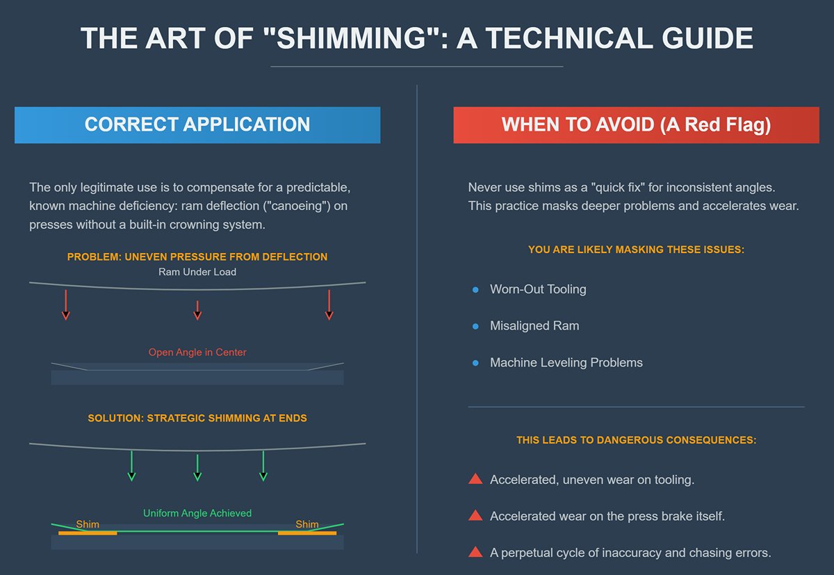
- The Correct Application: Shimming's legitimate purpose is to compensate for a predictable, known machine deficiency, specifically the natural deflection or "canoeing" that occurs in the center of an older press brake's bed and ram under load. On a long bend, this deflection can cause the angle in the middle to be more open than at the ends. By strategically placing shims under the die near the ends, you can slightly raise them, ensuring uniform pressure along the entire bend line. This is a valid workaround only if your machine lacks a built-in crowning compensation system.
- When to Avoid (The Professional's Warning): Shimming must never be a substitute for proper machine maintenance or a solution for worn-out tooling. If you find yourself shimming randomly to fix inconsistent angles, you are merely masking a deeper problem—be it uneven tool wear, a misaligned ram, or an issue with the machine's leveling. Regular reliance on shims is a red flag that accelerates uneven wear on both your tooling and your press brake, perpetuating a cycle of inaccuracy.
4.2 The First Bend and The Fine-Tuning Loop
With the tooling flawlessly installed, the final step is to bridge the gap between calculation and reality through a disciplined test bend and adjustment process. This is where you establish a repeatable, perfect result.
Rule #1: Always Use Scrap for the First Hit
Never perform the first bend on a valuable workpiece. Use a test piece of the exact same material and measured thickness to validate your setup.
The Systematic Adjustment Loop: Measure, Diagnose, Adjust
- Execute the Bend: Perform a single bend using your calculated parameters.
- Measure with Precision: Using a high-quality digital protractor and calipers, measure the actual bend angle and flange dimension.
- Adjust with Logic: If the flange dimension is incorrect, the error lies in your Back Gauge (X-axis) position. Make precise micro-adjustments forward or backward until the dimension is perfect. If the bend angle is incorrect, the error lies in your Ram Depth (Y-axis). If the angle is too open (e.g., 91°), you must increase the ram's penetration depth. If the angle is too acute (e.g., 89°), you must decrease it. Modern CNC controls allow you to simply input the measured angle, and the machine will calculate the precise Y-axis correction.
Institutionalize Success: Document Everything
This is the step that separates a shop that relies on "tribal knowledge" from one that owns a robust, scalable process. Once you achieve the perfect first piece, you must immediately and meticulously record the final, successful parameters. This setup sheet or process card becomes an invaluable asset for future runs and should include:
- Part Name / Drawing Number
- Material Type, Grade, and Actual Measured Thickness
- Punch Model and Radius
- Die Model and V-Opening
- Final, precise Back Gauge Position (X-axis)
- Final, precise Ram Depth (Y-axis)
- Resulting Measured Angle
- Crowning Value Applied (if any)
V. The Operator's Handbook for Maintenance, Diagnostics, and Troubleshooting
5.1 Quick Diagnostics Chart for Bending Defects
| Common Defect | Probable Tooling-Related Cause | Solution |
|---|---|---|
| Inconsistent Angles | Uneven wear on the V-die shoulders; Tooling deflection under load; Misalignment between punch and die. | Rotate the die to a fresh working surface or replace it; Utilize the machine's crowning system or apply shimming to compensate for deflection; Re-run the tool seating and alignment procedure. |
| Cracking on the Outside of the Bend | Punch tip radius is too small, falling below the material's minimum bend radius; Bend line is parallel to the material's natural grain direction. | Switch to a punch with a larger tip radius; Re-orient the part layout on the nesting software to ensure the primary bend is perpendicular to the material grain. |
| Surface Marking / Scratches | V-die shoulder radius is too sharp or has become sharp due to wear; Excessive tonnage; Metal debris is present on the tooling or workpiece. | Use a die with a larger shoulder radius; Place a mark-free protective polyurethane film between the material and the die; Thoroughly clean the tooling and material before bending. |
| Flange Too Short to Form | The physical body of the die (its "wall thickness") is too wide, causing the workpiece's short flange to collide with the side of the die during the bend. | Select a "narrow-shoulder" die with a more compact profile; Re-plan the bending sequence to form the shortest flange first, if possible. |
5.2 Reading the "Scars": Tracing Problems Back to Tool Wear Patterns
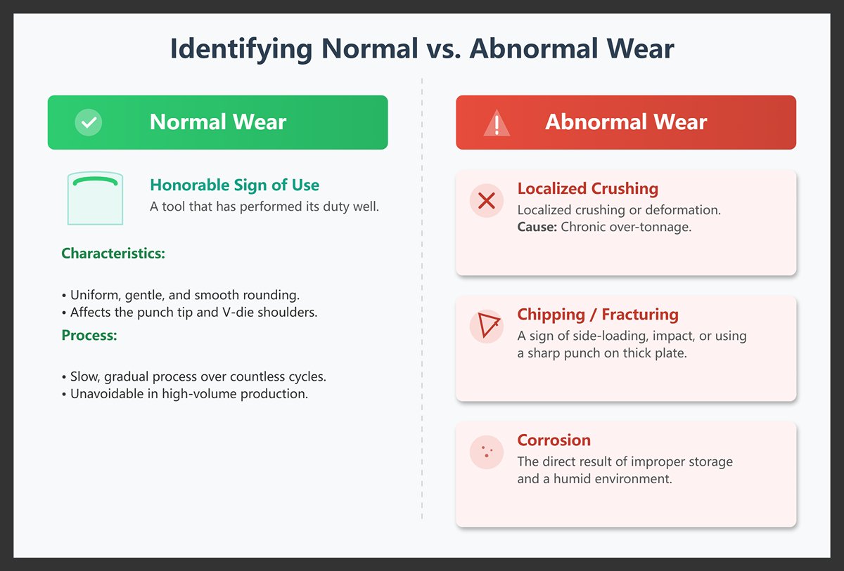
Identifying Normal vs. Abnormal Wear
- Normal Wear: This is the honorable sign of a tool that has performed its duty well. It manifests as a uniform, gentle, and smooth rounding of the punch tip and the V-die shoulders. It is a slow, gradual process that occurs over countless cycles and is an unavoidable consequence of high-volume production.
- Abnormal Wear: This is a red flag indicating a systemic problem. It includes localized crushing or deformation (often from chronic over-tonnage), chipping or fracturing (a sign of side-loading, impact, or using a sharp punch on thick plate), and corrosion (the direct result of improper storage and a humid environment). These are not signs of use; they are signs of abuse.
When to Resurface, Rotate, or Replace
- Resurface: For high-value, solid-piece tools with only minor, uniform wear, a professional regrinding service can restore the working surfaces to their original precision. This is a specialist's job, not a workshop task.
- Rotate: This is the most cost-effective life-extension strategy. For common tooling like four-way V-dies, once one V-opening shows wear, you can simply rotate the block 90 degrees to engage a brand-new, pristine working surface.
- Replace: This decision must be immediate and absolute. A tool must be removed from service permanently if it exhibits any visible cracks, severe localized deformation, or wear that exceeds the manufacturer's specification (typically 0.1mm - 0.2mm). A compromised tool is a direct threat to part quality, machine health, and operator safety.
The Hidden Costs of Using Worn Tooling
Continuing to use a worn-out tool is a classic example of "false economy." The perceived savings of avoiding a new purchase are dwarfed by the cascading costs it generates:
- Plummeting Quality: Scrap rates skyrocket as operators struggle to achieve consistent angles.
- Exploding Setup Times: What should be a quick adjustment becomes a lengthy battle of trial-and-error as the operator tries to compensate for the tool's unpredictable behavior.
- Accelerated Machine Wear: Uneven tool surfaces transmit unbalanced forces into the press brake's ram and bed, accelerating wear on the machine itself and compounding the problem.
5.3 The "Do's & Don'ts" of Tooling Maintenance and Storage
A rigorous maintenance and storage protocol is the single most effective way to protect your tooling investment and guarantee its long-term accuracy. These simple habits are as critical as any advanced bending technique.
Do's: The Rituals of a Professional
- Do Clean Religiously: After every use, thoroughly wipe down the tool with a soft cloth and a cleaning agent to remove all oils and metal particles.
- Do Apply a Protective Film: Once clean, apply a thin layer of anti-rust oil before storage. This is the ultimate barrier against corrosion.
- Do Store with Order: Use dedicated, non-wooden metal racks or cabinets. Store tools vertically or horizontally, categorized by type and size. Never stack tools directly on top of each other.
- Do Wear Gloves: Always handle clean tooling with gloves. The oils and moisture from your hands are a primary cause of rust spots.
Don'ts: The Cardinal Sins of Tooling Care
- Don't Exceed Tonnage: Never surpass the tool's maximum rated load capacity. This is the number one cause of permanent, catastrophic tool failure and a grave safety risk.
- Don't Use a Hammer: Never strike a hardened tool with a hard object, especially a steel hammer. The tool's high hardness makes it brittle; a sharp impact can cause it to shatter like glass.
- Don't Stack Casually: Leaving tools in a disorganized pile on a workbench or the floor is a guarantee of nicks, dings, and potential accidents.
- Don't Use Wood for Storage: Avoid wooden shelves or pallets. Wood is hygroscopic—it absorbs moisture from the air and holds it directly against your tool's surface, creating an ideal environment for rust.
VI. Conclusion
In summary, press brake tooling is the crucial component that shapes sheet metal, directly impacting product quality, production efficiency, and costs. Understanding the types of punches and dies, their materials, and selection principles such as the five-step method and the “8x rule” is essential for precision bending. Proper installation, adjustment, and maintenance ensure consistent performance and reduce defects.
For expert advice and high-quality tooling solutions tailored to your needs, explore our Brochures or contact us today. Our experienced team is ready to support your journey toward efficient and precise metal fabrication.


