I. Introductory Section
In metal fabrication, the development of press brake technology is becoming more and more critical, especially the training for its operation skills. Our passage aims to delve into the professional training of the press brake. This is not merely for technology transmission but for overall improvement of safety and efficiency.
Press brake training is not only related to the personal skills of operators but also product quality, production efficiency, and the operator's safety. Improper operation may cause production accidents and affect the final precision and appearance of the product.
Therefore, professional press brake training becomes the key to ensuring safe working and highly efficient production. Our passage will start with the basic concept of the press brake, the choice of training course, safety protocols, maintenance training, and so on. I hope it will be beneficial to you.
II. Understanding Press Brake Machinery
2.1 Fundamentals of Press Brake
Press brake is a device used for bending and forming metal sheets. It is made up of upper dies and bottom dies and makes the metal sheet bend and deform into the required angle and shape through exerting pressure.
The primary function of the press brake is to achieve precise bending, thus ensuring the metal sheet is in the required shape and size.
2.2 Types
Common types of press brakes are divided into the following:
Mechanical press brake: it exerts pressure through the mechanical transmission system (like crankshaft, gears, and connecting rods). It features a simple structure, low cost, and relatively slow speed and precision.
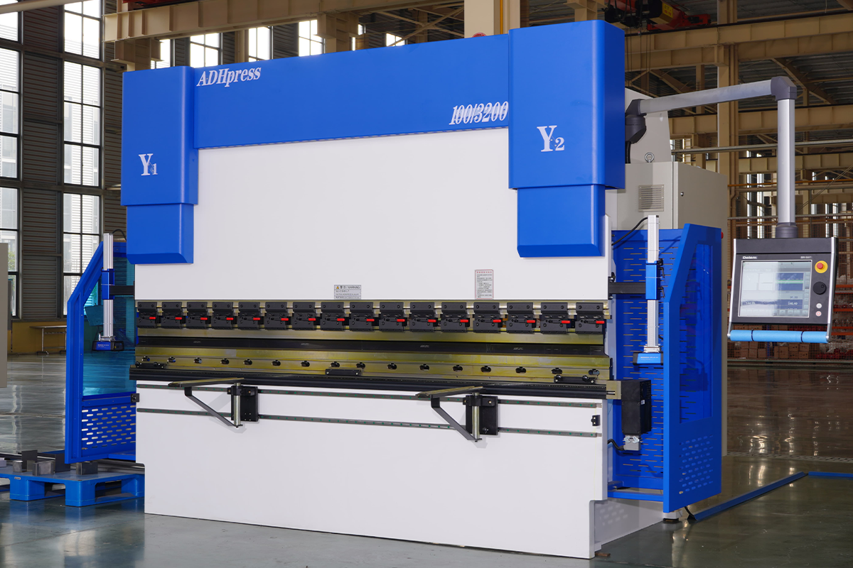
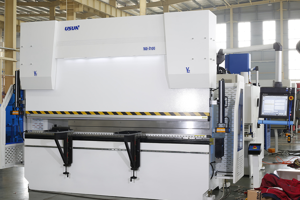
Hydraulic press brake: it uses a hydraulic cylinder to generate the pressure. It is better than mechanical press brakes in precision and force and is suitable for mass-scale, high-precision bending requirements.
Electric press brake: it uses a servo motor to control the bending force. The electric press brake performs well in speed, precision, and energy consumption and is suitable for fine processing.
2.3 Key Components
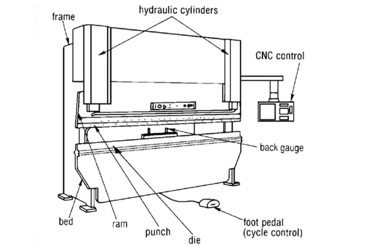
Bed: as the main frame of the machine, it bears the weight of the whole machine and ensures stability during the processing period.
Ram: it exerts pressure on the metal sheet during the bending process. The precise control of the ram directly affects the bending quality.
Die: the die is usually made up of the upper and bottom die, which are used to form the specific bending shape. The design of the die and material is essential for processing precision and product quality.
Backgauge device: it is used to position the sheet to ensure bending precision and repeatability.
Control system: it is the brain of the press brake and is used to set and control the processing parameters, like pressure, speed, and location.
Ⅲ. Breaking Through and Innovating: Why Mastering the Press Brake Is a Golden Skill in Modern Manufacturing
In today's manufacturing landscape, the role of the press brake operator is being redefined. No longer simply a machine attendant, these professionals are engineers, mathematicians, and artists rolled into one—precision forming specialists. Mastering the press brake means commanding a skill that directly impacts a company’s safety, quality, efficiency, and profitability. This guide lays out a full-spectrum competency map from novice to expert, helping you advance from “machine operator” to “precision sheet‑metal craftsman.”
3.1 Redefining the Press Brake: More Than a Machine—The Artistry at the Core of Precision Forming
A press brake is far more than a tool for bending metal sheets—it is the heart of precision forming. From aircraft wing ribs and electronic casings to automotive chassis components, the foundation of these complex three‑dimensional shapes lies in an operator’s ability to transform flat sheet into precisely shaped parts. By selecting suitable upper and lower dies, a press brake can perform various processes including Air Bending, Bottom Bending, and Coining, each involving distinct strategies for precision, efficiency, and springback control. Thus, understanding a press brake means grasping an integration of material mechanics, geometry, and process sequencing.
3.2 The Value of Skill: How Exceptional Operators Drive Safety, Quality, and Profit
Highly skilled press brake operators are invaluable assets to any manufacturer. Their impact is most evident across three critical dimensions:
(1) Safety
A press brake exerts hundreds of tons of force, and improper operation can lead to severe injury or equipment failure. Skilled operators not only follow essential protocols—such as wearing PPE—but also anticipate risks, correctly configure safety systems like light curtains and dual‑hand controls, and react swiftly in emergencies. They are the final safeguard in maintaining a safe production environment.
(2) Quality
Up to 90% of a part’s dimensional accuracy depends on the bending stage. Expert operators understand and calculate Bend Deduction and K‑Factor, predict material extension and Springback during bending, and achieve micron‑level tolerances. Their precision reduces the need for grinding, streamlines subsequent welding and assembly, and ensures consistent product quality.
(3) Profitability: Technical mastery translates directly into financial performance.
- Reduced Waste: Accurate setup and trial bends prevent costly scrapping due to wrong angles or dimensions.
- Improved Efficiency: Skilled operators read drawings quickly, configure machines efficiently, and optimize bending sequences to shorten production cycles.
- Cost Reduction: Precision bending leads to smaller weld seams and less filler use in later processes, saving materials and labor hours.
- Business Expansion: Complex orders requiring intricate bends—such as joggles or extremely tight tolerances—can only be executed by top‑tier operators, determining whether a factory can secure high‑value projects.
3.3 The Spirit of Mastery: The Mindset Shift from “Machine Operator” to “Precision Craftsman”
The transformation from operator to craftsman centers on a shift in thinking. It’s not only about “how to operate” but “why” and “how to optimize.”
| Mindset | Machine Operator | Precision Sheet‑Metal Craftsman |
|---|---|---|
| Core Focus | Completing the current bending task | Considering the part’s entire life cycle and final assembly performance |
| Approach to Drawings | Follows the blueprint for dimensions and angles | Interprets the designer’s intent and anticipates potential issues |
| Problem Handling | Reacts to problems as they arise | Prevents issues proactively by optimizing process flow and parameter settings |
| Knowledge Base | Familiar with operation interface of specific machine models | Understands materials science, tooling, CNC programming, and geometric principles |
| Role Definition | An executor on the production line | The key node in quality control—a process expert bridging design and manufacturing |
This mindset shift means thinking like an engineer—focusing not only on how to bend but why it should be done that way, treating every operation as an opportunity for process experimentation and improvement.
3.4 Your Personalized Growth Path: A Roadmap for Beginners, Advanced Operators, and Future Technical Experts
Mastery of the press brake does not happen overnight—it requires structured learning and hands‑on practice. The following is a roadmap designed to guide you from entry level to professional mastery.
(1) Stage One: Beginner (0–1 Year)—Safety First, Build a Solid Foundation
This stage focuses on developing strong safety awareness and learning the machine’s basic operations.
Core Competencies:
- Safety Awareness: Understand and strictly follow all safety procedures, including PPE use, safety light curtain setup, and emergency stop functions.
- Machine Familiarity: Learn the main components (frame, ram, worktable, back gauge, control system) and machine types (mechanical, hydraulic, electro‑hydraulic servo).
- Basic Operation: Practice start‑up, shut‑down, referencing, and fundamental manual control tasks.
- Tooling Basics: Identify standard punches and dies (V‑grooves) and understand basic selection principles for material thickness, such as the “eight‑times rule.”
- Simple Part Bending: With guidance, complete basic parts involving one or two bends.
- Learning Resources: Equipment manuals, shop safety training, and mentorship from experienced operators.
- Milestone: Achieve the ability to safely and independently perform simple bending tasks without supervision.

(2) Stage Two: Advanced Operator (1–3 Years)—Pursuing Precision and Efficiency
The goal in this stage is to improve bending accuracy and efficiency while gaining an understanding of underlying process principles.
Core Competencies:
- Technical Drawing Interpretation: Confidently read and analyze complex engineering drawings, including tolerances, angles, and bend radii.
- Process Calculation: Master calculations for flat pattern development, bend deduction, and springback compensation.
- CNC Programming: Learn to program NC or CNC systems—setting bending angles, back‑gauge positions, pressures—and optimize bending sequences to prevent interference.
- Tooling Expertise: Accurately select die combinations based on material type, thickness, and bend radius, including special tools such as gooseneck and acute‑angle dies.
- Quality Control: Use protractors and calipers for precise measurement and correct deviations by adjusting program parameters.
- Troubleshooting: Identify and resolve common issues such as incorrect angles, scratches, or marks on parts.
- Learning Resources: Professional training from organizations like the FMA (Fabricators & Manufacturers Association, International), tooling supplier manuals, and online simulation software.
- Milestone: Capable of independently programming and performing trial runs for complex, multi-bend parts, ensuring consistency throughout mass production.
(3) Stage Three: Technical Expert / Master Fabricator (3+ years) — Innovation and Legacy
At this level, you become the go-to expert for solving complex problems and serve as the technical backbone of your team.
Core Competencies:
- Advanced Techniques: Master of hemming, joggle/offset bending, large-radius step bending, and other complex processes.
- Extreme Challenges: Able to handle unconventional bending tasks, such as ultra-small flanges or intricate geometries, pushing both machine and tooling to their limits.
- Process Optimization and Innovation: Not only execute existing processes but also refine them—design new bending approaches or propose non-standard tooling to enhance efficiency and quality.
- System-Level Troubleshooting: Skilled at diagnosing and addressing complex equipment issues involving hydraulic systems, electrical control, and software.
- Knowledge Transfer and Leadership: Capable of training new operators, developing standard operating procedures (SOPs), and serving as a technical advisor to engineers in Design for Manufacturing (DFM).
- Learning Resources: Advanced technical seminars, in-depth collaboration with machine and tooling manufacturers, and participation in new product development projects.
- Milestone: Become the team’s recognized “go-to” expert—able to resolve any bending challenge and generate irreplaceable value for the company through your skill and expertise.
The journey from operator to master craftsman is long but profoundly rewarding. It reflects not just career advancement or financial gain, but a deeper commitment to transforming cold metal into precise, functional forms through skill and intellect—a true craftsman’s spirit.

Ⅳ. Safety First: The Unbreakable Code for Zero-Accident Operation
In the world of bending and forming, precision and efficiency matter—but safety stands above all as the unshakable cornerstone, the ultimate rule. According to the U.S. Occupational Safety and Health Administration (OSHA), inadequate machine guarding ranks among the top ten most frequently cited violations, with over 88% classified as serious. Each year, hundreds of severe injuries—ranging from crush injuries to amputations—occur in press brake operations. Thus, for a true master-level operator, safety must evolve beyond manuals into a guiding mindset—building an impregnable wall against accidents.
4.1 Accurate Hazard Recognition: Detecting Pinch Points, Kickbacks, and Hidden System Risks
Professional risk recognition is the first line that separates novices from experts. Dangers aren’t just visible—they often lurk deep within machinery or in the repetition of daily tasks.
4.1.1 Physical Injuries: Common Crushing, Pinching, and Cutting Scenarios and Prevention
This is the most direct—and brutal—risk.
(1) Point of Operation
Crushing: The most hazardous zone on a press brake—the point where the punch and die meet. In the instant of closure, the enormous pressure can cause devastating crush injuries or even amputations.
Highest-Risk Action: When operators, seeking speed or handling small parts, reach into the operation area to steady or position a workpiece.
Prevention Principle: Always assume that safety devices can fail—keep your hands completely away from the die closure zone.
(2) Backgauge Pinch Points
Automated backgauge systems can move rapidly and quietly under program control, creating multiple concealed pinch points between guide rails and the machine frame. Focused on the front workpiece, operators may easily overlook dangers behind them.
Prevention Principle: Treat the rear of the machine as a “no-entry zone.” Make adjustments or retrieve parts only when the program is paused and the backgauge is completely stationary.
(3) Material Kickback and Cutting Hazards
When bending long, thin sheets, the free end can whip upward rapidly as the angle forms, striking anyone within range. Additionally, freshly cut sheet edges are extremely sharp and can cause deep lacerations.
Prevention Principle: Anticipate the material’s path during bending—ensure no one is within its swing range; always wear cut-resistant gloves when handling sheet metal.
4.1.2 System Risks: Potential Failures in Hydraulic, Electrical, and Control Systems
The machine itself represents another major source of danger—a seemingly stable system can fail unexpectedly for many reasons.
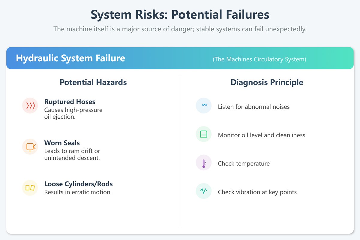
(1) Hydraulic System Failure
Often called the machine’s circulatory system, potential hazards include ruptured hoses causing high-pressure oil ejection, worn seals leading to ram drift or unintended descent, and loose cylinders or connecting rods resulting in erratic motion.
Diagnosis Principle: Listen for abnormal noises such as pump rattling or impact sounds, monitor oil level and cleanliness, and check temperature and vibration at key points—these serve as diagnostic indicators of system health.
(2) Electrical and Control System Failures
Issues may include malfunctioning control buttons, error messages on control panels, servo motor faults, or failed limit switches and sensors. The most dangerous scenario occurs when signal confusion triggers unintended machine movements. Accidental activation of foot switches is also a common cause.
Diagnosis Principle: Never ignore error codes on a control system. Ensure foot pedals are protected by guards and fixed securely to prevent accidental activation.
(3) Unknown Risks with Used or Older Equipment
Extra caution is needed when purchasing or using secondhand machines—their safety systems may be outdated, bypassed, or missing entirely, and may not comply with current ANSI B11.3 standards.
Prevention Principle: Always have qualified professionals conduct a comprehensive safety audit and risk assessment before operating any non-new machine.
4.1.3 Occupational Health: Managing Noise, Dust, and Ergonomic Hazards
These are the slow, cumulative threats—the “boiling frog” type injuries that can silently destroy an operator’s long-term health.
(1) Noise
Press brakes—particularly older hydraulic models—produce continuous high-decibel noise during operation cycles, and long-term exposure can lead to permanent hearing loss.
(2) Ergonomic Strain
Repeatedly lifting, positioning, and aligning heavy metal sheets, or maintaining awkward postures such as bending or leaning forward, can cause chronic musculoskeletal strain—especially in the back, shoulders, and wrists.
(3) Management Principles
Always wear hearing protection (earplugs or earmuffs); use lifting tables, suction tools, or assistive devices to reduce physical stress; place anti-fatigue mats at workstations; and perform regular stretching to avoid prolonged static postures.
4.2 Shields of Life: Proper Use and Verification of Key Safety Devices
Safety devices are not decorative—they serve as the final line of defense protecting lives. Knowing how to use them is essential; knowing how to verify their effectiveness defines true professionalism.
4.2.1 Active Safeguards: Light Curtains, Two-Hand Control, and Laser Safety Systems
These devices are designed to prevent accidents before they happen.
(1) Light Curtains
In front of the operating point, one or more invisible grids of infrared beams are created. As soon as the operator’s hand or any object breaks a beam, the control system immediately halts the ram’s movement. This is one of the most essential safety features of a modern hydraulic press brake.
(2) Laser Safety System (AOPDs)
This is a more advanced form of active protection. The emitter and receiver are mounted on the ram, moving together with it to form a protective zone just beneath the punch tip. It allows workpieces—such as box sidewalls—to enter the protected area without triggering a stop, while precisely detecting the intrusion of a finger. The result is a well-balanced combination of safety and productivity.
(3) Two-Hand Control
The operator must press two buttons positioned apart from each other at the same time to initiate the ram’s downward stroke. The logic is simple: if both hands are on the buttons, they cannot be in the hazardous die area.
(4) Verification Practice
The very first task each day: verify the safety systems! Use a test bar (usually supplied by the machine manufacturer) to deliberately block the light curtain or laser protection zone at different speeds and stroke lengths, confirming that the ram stops instantly. For the two-hand control, test single-hand and asynchronous presses to ensure the machine never activates. Any failed verification requires immediate shutdown and reporting.

4.2.2 Passive Safeguard: Emergency Stop (E-Stop) Response Mechanism
When active protection fails or any unexpected situation occurs, this is the final measure to halt all dangerous motion.
(1) Emergency Stop Button (E-Stop)
A large, bright red mushroom-shaped button. Striking it cuts off both power and control circuits, bringing all moving components to a full stop.
Every operator must develop muscle memory for the E-Stop’s exact location. Remember: although pressing the E-Stop can avert an emergency, it’s a forceful shutdown that may require system reinitialization. Most importantly, the E-Stop must never be used as a routine power switch—and absolutely never as a substitute for the LOTO procedure!
4.2.3 Personal Protective Equipment (PPE): A Complete Head-to-Toe Checklist
PPE is your body’s final layer of armor. Wearing it properly isn’t about passing inspections—it’s a commitment to your own life.
| Protection Item | Requirements |
|---|---|
| Eye Protection | Always wear safety-rated goggles to prevent metal fragments from entering your eyes. |
| Hand Protection | Wear appropriate cut-resistant gloves, especially when handling raw materials or finished parts. Note: never wear gloves when operating rotating machinery, though press brake use is an exception. |
| Foot Protection | Wear steel-toe safety shoes to prevent injuries from falling heavy objects or sharp sheet edges. |
| Hearing Protection | In high-noise environments, wear earplugs or earmuffs. |
| Dress Code | Wear well-fitted work clothes. No jewelry or ties, and long hair must be tied up. Loose clothing or accessories can easily get caught in moving machinery. |
4.3 Lockout/Tagout (LOTO): The Safety Lifeline for Tool Changes and Maintenance
LOTO is a strict, formal procedure designed to ensure that hazardous energy sources are fully isolated and locked out during maintenance or repair, preventing accidental release. In press brake operations, it is most often used for die changes and equipment servicing. Ignoring LOTO is like dancing on the edge of a cliff.
(1) The Deadly Misconception
“I’m just swapping a small die; it’ll only take a few minutes—no need for LOTO.” This mindset is the cause of countless accidents. OSHA clearly mandates that whenever any part of an employee’s body enters a danger zone, energy control procedures must be implemented. Die changes fall squarely under this definition, and the so-called “routine, repetitive minor service” exemption rarely applies here.
(2) The Standard Six-Step LOTO Procedure:
- Prepare: Identify all energy types (electrical, hydraulic, pneumatic, gravitational, etc.) and their isolation points.
- Shutdown: Turn off the machine following normal procedures.
- Isolate: Disconnect all energy sources, such as opening breakers or closing hydraulic valves.
- Lock & Tag: Attach locks to every isolation point and affix tags showing the operator’s name and time. Every maintenance participant must apply their own lock.
- Release Stored Energy: Discharge any residual energy—bleed hydraulic pressure, wait for flywheels to stop completely, or use safety blocks to physically support the ram against gravity.
- Verify: Attempt to start the machine (press the start button) to confirm it cannot be powered on before beginning work.
Keep your key in your own pocket—your life is in that pocket. Never let anyone else lock or unlock on your behalf, and never skip a single step for convenience, especially the “Verify” step.
4.4 Embedding a Safety Culture: Integrating SOPs, 5S, and Continuous Improvement into Daily Practice
Zero-accident goals cannot be achieved by systems and machines alone; they ultimately rely on a deeply ingrained safety culture.
(1) Standard Operating Procedures (SOPs)
An SOP is not a document to gather dust—it is a guide to best practices for every operation. A good SOP details every step from pre-start inspections and material handling to shutdown cleaning, with clear safety notes at each stage. Making SOP compliance a habit is the foundation of standardization.
(2) 5S Management
5S (Seiri, Seiton, Seiso, Seiketsu, Shitsuke) forms the bedrock of safety management. A clean, organized, and orderly workspace inherently reduces slip and trip hazards and helps operators maintain focus. Properly arranged tools and dies also significantly minimize risks during changeovers.
(3) Continuous Improvement (Kaizen)
Safety has no finish line—only continuous improvement. Encourage operators to report near misses and potential hazards, treating them as opportunities for learning rather than grounds for blame. Treat every safety audit and pre-shift meeting as a chance to improve. Once this mindset takes root, safety becomes everyone’s second nature.
Ⅴ. Theoretical Foundations: The Science and Mathematics Behind Precision Bending
If safety is the foundation of operation, then a solid grasp of the underlying scientific and mathematical principles is the pathway to mastery in precision sheet metal work. True craftsmanship doesn’t rely on vague “feel”—it’s built on exact understanding of drawings, materials, mechanics, and geometry. This chapter reveals the logic behind perfect bends, helping you establish an unshakable theoretical base.
5.1 Blueprint Literacy: From 2D Drawings to 3D Spatial Imagination
An engineering drawing is the most precise conversation between designer and builder. To truly read it is not merely to decode numbers, but to grasp the three-dimensional intent and functional purpose behind them.
5.1.1 Interpreting Views and Tolerances: Mastering GD&T to Reveal Design Intent
A standard sheet metal drawing typically includes front, top, and side views, but the true essence of a part lies in its tolerances. A master-level operator can extract two kinds of information from a drawing:
(1) Explicit Instructions
For instance, a hole tolerance marked ±0.1 mm is an absolute rule that must be followed. More advanced drawings use Geometric Dimensioning and Tolerancing (GD&T). A hole marked with a position tolerance symbol means its relative position to a reference hole is more critical than its exact coordinates. Understanding this allows you to prioritize adjustments—knowing which dimensions can be fine-tuned and which must remain uncompromised.
(2) Implicit Intent
For example, a dimension without a specified tolerance doesn’t mean “no limit.” It follows the shop’s general tolerance standard (such as ISO 2768-mK). More importantly, you should ask: “What is the function of this flange—does it serve as a mounting edge of the casing or as an internal reinforcing rib?” If it’s a mounting edge, its fit with adjacent parts is paramount—even if you sacrifice a bit of angular precision, the mating dimensions must be exact. This kind of engineering mindset distinguishes a skilled operator from a true process expert.
5.1.2 Understanding Bending Parameters: The Relationship Between Bend Radius, Angle, and Flat Pattern Length
Every bend is defined by three key parameters: the inside bend radius (r), the bend angle (θ), and the material thickness (t). Together, these determine the part’s final geometry and, most crucially, the Flat Pattern Length. To visualize this, imagine a flat sheet being bent—the outer layer stretches while the inner layer compresses. This means the material in the bend zone doesn’t behave as a simple linear addition; precise calculations are needed to compensate for the difference. This is where all flat pattern length computations begin.
5.2 Understanding Material Behavior: Mastering the “Personality” of Different Metals
Metals are far from uniform substances. Each type has its own mechanical “temperament.” Appreciating these differences is essential for achieving consistent, high-quality bending results.
5.2.1 Key Performance Indicators: Effects of Yield Strength, Ductility, and Grain Direction
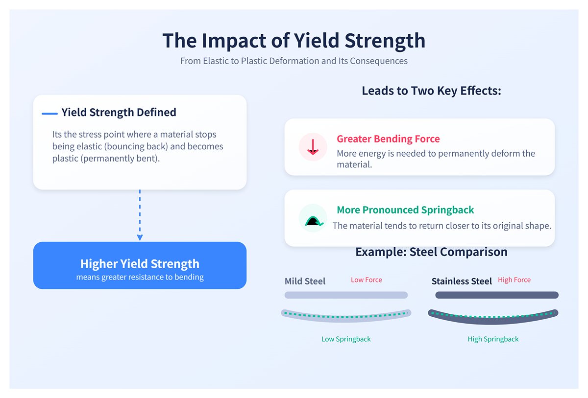
(1) Yield Strength
The yield strength marks the threshold where a material shifts from elastic to plastic (permanent) deformation. The higher the yield strength, the more the material resists bending, leading to two direct consequences:
① Greater bending force required;
② More pronounced springback.
For example, stainless steel has a much higher yield strength than mild steel, which makes its springback considerably larger.
(2) Ductility
Ductility refers to a material’s ability to undergo plastic deformation before fracturing. The higher the ductility, the more flexible the material, allowing smaller bend radii without cracking. Low-ductility materials (such as certain high-strength aluminum alloys) may develop surface cracks on the outer side if forced into tight bends.
(3) Grain Direction
During rolling, the metal’s internal grains elongate along the rolling direction, forming an invisible “texture.” This grain direction is a crucial but often overlooked parameter:
(4) Bending With the Grain (bend line parallel to the grain direction)
Much like splitting wood along its grain, this can easily cause cracking and should be avoided whenever possible.
(5) Bending Against the Grain (bend line perpendicular to the grain direction)
This is the ideal method—materials can withstand greater deformation without cracking.
(6) Insider’s Tip
Experienced technicians consider grain direction when laying out sheet nests, ensuring that critical bends with small radii run against the grain for maximum strength and quality.
5.2.2 Material Comparison: Quick Reference for Steel, Stainless Steel, and Aluminum Alloy Bending Characteristics
| Material Type | Typical Yield Strength | Springback Characteristics | Recommended Minimum Bend Radius (r/t) | Bending Notes |
|---|---|---|---|---|
| Low-Carbon Steel (e.g., Q235) | Low | Minimal | ≈ 0.5–1.0 × sheet thickness (t) | Easiest to form, ideal for beginners learning bending techniques. |
| Stainless Steel (e.g., 304) | High | Maximum | ≥ 2.0 × sheet thickness (t) | Strong work-hardening tendency; requires higher tonnage and precise springback compensation. |
| Aluminum Alloy (e.g., 5052) | Moderate | Relatively High | ≥ 1.5–2.0 × sheet thickness (t) | Soft material; prone to scratches and marks—surface protection recommended. |
| High-Strength Steel (e.g., HARDOX) | Extremely High | Very Large | ≥ 3.0 × sheet thickness (t) | Requires massive tonnage and wide V-dies; springback is difficult to control and represents the ultimate bending challenge. |
Note: The r/t ratios above are empirical guidelines. Accurate values should be verified using material reference charts or experimental data.
5.3 Overcoming Springback: The Core Secret to Precision Angle Control
Springback is a constant challenge in bending operations—it occurs when the material elastically recovers after the pressure is released, causing the bend angle to “bounce back.” For example, if you intend to make a 90° bend but release the pressure and end up with 91°, you’ve experienced springback. Mastering springback control is the hallmark of an expert operator.
5.3.1 Understanding Springback Mechanics and Determining the Springback Factor
Springback magnitude is mainly influenced by three factors: higher material yield strength increases springback, larger bend radius-to-thickness ratios increase springback, and wider V-die openings increase springback. Traditionally, it can be quantified using the Bend Springback Factor (BSF) or by directly measuring the springback angle. For hands-on operators, however, effective compensation strategies matter most.
5.3.2 Three Angle Compensation Strategies: Intuitive Judgment, Trial Bending, and CNC Auto-Adjustment
(1) Intuitive Method (“The Veteran’s Instinct”)
Through years of experience, skilled operators develop an internal knowledge base: “For 2 mm stainless steel with a 20 mm V-die, to achieve a true 90°, I’ll set the program to 87.5°.” This method is fast but highly personal—less reliable when working with new materials or unfamiliar setups.
(2) Trial Method (“The Scientist’s Precision”)
The most dependable and time-tested approach. Use a scrap piece from the same material batch for a test bend, measure the actual angle with a precision protractor, then adjust the CNC angle compensation accordingly. Achieving perfection on the first production part is often the result of one rigorous, data-driven iteration.
(3) CNC Automatic Compensation (“Modern Technology’s Magic”)
This is the trump card of high-end press brakes. By integrating a laser or contact-based angle measurement system, the machine continuously monitors the bending angle in real time. If the system detects that the target angle has not yet been achieved (for instance, springback will leave the part at 90.5°), it automatically commands the ram to press down slightly further until the predicted post-springback angle is precisely 90°. This marks a breakthrough from open-loop control to true closed-loop feedback.
5.4 K-Factor in Practice: From Theoretical Formulas to Accurate Flat-Length Calculations
If mastering springback control ensures angular accuracy, then understanding the K-Factor ensures dimensional accuracy. It’s the secret key to calculating precise flat-developed lengths.
5.4.1 Definition and Influencing Factors of the K-Factor
Imagine a bent metal sheet: the outer surface stretches while the inner surface compresses. Between them lies a region that experiences neither tension nor compression—this is the Neutral Axis. The K-Factor represents the ratio of the distance from this neutral axis to the inner surface of the sheet, relative to the total thickness of the material.
(1) Function of the K-Factor
All flat-length calculations essentially involve summing the lengths of the straight sections plus the arc length along the neutral axis within the bend. The K-Factor directly determines that arc length.
(2) Insider’s Tip: The K-Factor is not a fixed constant!
It varies depending on material type, bend radius, sheet thickness, and bending method (air bending vs. bottoming). Typically, softer materials like aluminum have higher K-Factors than harder materials like steel, and larger bend radii yield higher K-Factors than smaller ones. A common mistake is using the default 0.44 or 0.5 value in software, which often leads to significant dimensional errors.
5.4.2 Deriving an Accurate K-Value Experimentally for a Specific Process
One hallmark of a true expert is independence from generic K-Factor charts. Instead, they build their own workshop-specific K-Factor database tuned to particular material–tooling combinations. Here’s how:
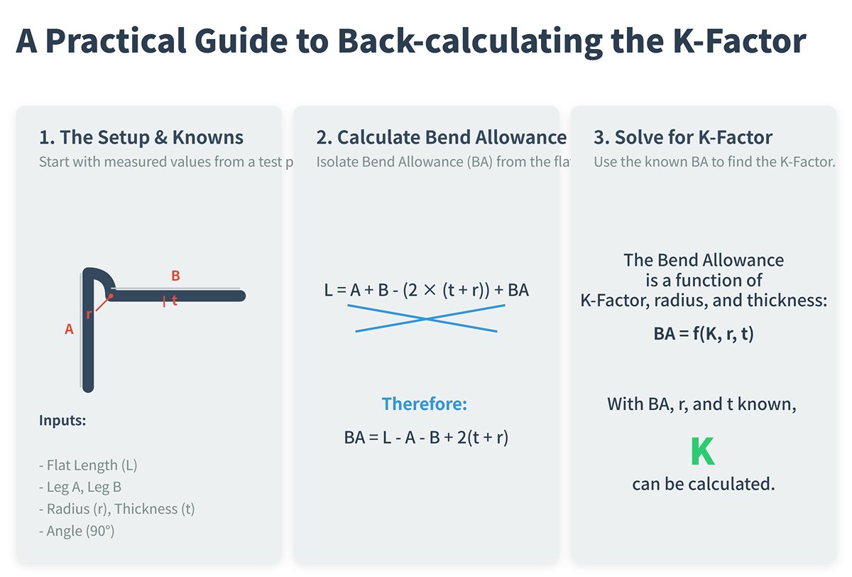
(1) Prepare the sample: Select a sheet with precisely measured length and thickness (for example, L = 200 mm, t = 2.0 mm).
(2) Bend accurately: Using the tooling combination under study (e.g., punch radius R1, die opening V16), make a precise 90° bend at the center of the sheet.
(3) Measure results: Use a caliper to measure the external flange lengths A and B after bending.
(4) Back-calculate: With simple geometry, you can determine the actual flat length of the bent zone from A, B, r, t, and the 90° angle, and from there compute the precise K-Factor for that specific setup.
- Flat length L = A + B - (2 × (t + r)) + Bend Allowance (BA)
- Bend Allowance BA = f(K, r, t)
- With known L, A, B, t, and r, you can solve for K.
(5) Build your database: Record the calculated K-value, noting the corresponding material, thickness, punch, and die used. Repeat this for your commonly used setups to compile a “K-Factor Quick Reference Table.” If your CAD/CAM software permits, import these values into its material library.
Though this process may seem tedious, the payoff is immense. It frees your flat pattern calculations from guesswork and delivers unprecedented precision. Once you understand a material’s “personality,” the “patterns” of springback, and the “code” of the K-Factor, you’ve truly mastered the scientific essence of accurate bending.
Ⅵ. Mastering the Tools: Deep Insight and Efficient Synergy Between Machine and Tooling
Having established the principles of safety and theory, we now arrive at the heart of “to do a good job, one must first sharpen their tools.” A press brake and its tooling are like the brush and ink of a calligrapher—their performance, alignment, and condition directly shape the final result. This chapter dissects the intricate inner workings of this precision system, guiding you from a simple operator to a master who can communicate intelligently and efficiently with both machine and tooling.
6.1 Machine Anatomy: Key Components from Frame and Ram to Backgauge
To truly understand a press brake, you must see beyond its steel body and appreciate the delicate interplay of each component in balancing force and precision. The frame and bed form the “skeleton” of the machine—their rigidity directly affects dimensional stability under heavy loads. When bending thick plate, even micron-level deflection at the center can affect angular consistency. To counter this, high-end machines employ crowning systems that apply compensating force beneath the bed, keeping the upper and lower tools perfectly parallel, ensuring uniform angles across the entire workpiece.
The ram is the machine’s “arm,” carrying the punch and executing the downward forming motion. Its repeat positioning accuracy determines angle consistency from part to part. Modern servo-hydraulic systems deliver exceptional control, maintaining repeat accuracy within ±0.002 mm, enabling reliable, repeatable production of perfectly formed parts.
The backgauge system serves as the machine’s “ruler,” precisely positioning the workpiece to define flange length and bend location. It has evolved far beyond single-axis designs into a multi-axis intelligent system. The R-axis controls vertical adjustment to accommodate different die heights or complex part geometries; the Z1 and Z2 axes move independently for asymmetric or tapered bends. The synchronized, high-speed motion of these axes not only ensures accuracy but also significantly enhances productivity and part versatility—an elegant fusion of precision and efficiency emblematic of modern manufacturing.
6.2 Power System Comparison: Hydraulic, Servo, and Hybrid Press Brakes – Strengths, Weaknesses, and Selection Guidelines
The “heart” driving the ram’s motion—the power system—determines the machine’s character and energy efficiency.
| Power System Type | Working Principle & Features | Advantages, Disadvantages & Selection Advice |
|---|---|---|
| Conventional Hydraulic Press Brake | A large hydraulic pump runs continuously, with proportional valves directing oil into the cylinders to drive the ram. | Advantages: Mature technology, high tonnage capacity, relatively low cost. Disadvantages: Constantly running pump causes high energy consumption and noise; oil temperature variations lead to angle drift; slower response speed. Selection: Best for heavy-duty or thick-plate bending, or cost-sensitive operations. |
| All-Electric Servo Press Brake | Driven entirely by servo motors via ball screws or belts, with no hydraulic system. | Advantages: Extremely high response speed and positioning accuracy; energy use only during bending (30–50% that of hydraulics); very low noise; clean operation with no hydraulic oil. Disadvantages: Limited tonnage (typically below 200 tons); highest initial investment. Selection: Ideal for precision thin-sheet work, electronics, and medical applications requiring speed, accuracy, and cleanliness. |
| Electro-Hydraulic Hybrid Servo Press Brake | Combines the strengths of both systems, using a servo motor to drive the hydraulic pump. The motor operates only when pressure is required, precisely controlling oil flow. | Advantages: Merges the power of hydraulics with the precision, energy efficiency, and quick response of servo systems; the current mainstream in the high-end market. Disadvantages: More complex technology and higher cost than conventional hydraulics. Selection: The top choice for modern sheet-metal shops pursuing high efficiency, accuracy, and low operating costs. |
Think of these systems as the engines of a car: the traditional hydraulic press brake is like a large-displacement V8—brute power but thirsty; the all-electric servo model resembles a Tesla—quiet, fast, and efficient; while the hybrid drive is akin to a high-performance hybrid sports car, delivering explosive force when needed and remaining economical during steady operation.
6.3 Masterclass on the Die System: A Complete Guide to Selection, Installation, and Maintenance
If the machine is the arm, then the die is the deft "fingers"—the part that directly touches the workpiece and shapes its final form. The depth of your understanding of the die directly defines the upper limit of your craftsmanship.
6.3.1 Types, Materials, and Visual Selection Guide of Punches (Upper Dies) and Dies (Lower Dies)
- Punch (Upper Die): Common types include the standard straight punch (for general applications), the gooseneck punch (used to avoid interference when bending U-shaped or flanged parts), and the acute-angle punch (for compensating the large springback of high-strength steel).
- Die (Lower Die): The most common type is the V-groove die with various opening widths. The width of the opening determines the bend radius and required tonnage during free bending.
- Material and Treatment: Dies are usually made of high-strength alloy tool steel (such as 42CrMo). To resist wear during high-strength or high-volume production, their working surfaces are induction hardened or fully heat-treated. Premium dies may also undergo nitriding or receive a TiN coating to significantly extend service life.
6.3.2 The Golden Rule for V-Groove Selection: The "8× Material Thickness" Principle and Its Refinements
(1) The Classic Rule
For low-carbon steel with a tensile strength of about 450 N/mm², the V-groove width (V) is typically eight times the material thickness (t), that is:
V = 8 × t
Under this condition, you’ll obtain an ideal inner bend radius approximately equal to the material thickness (r ≈ t).
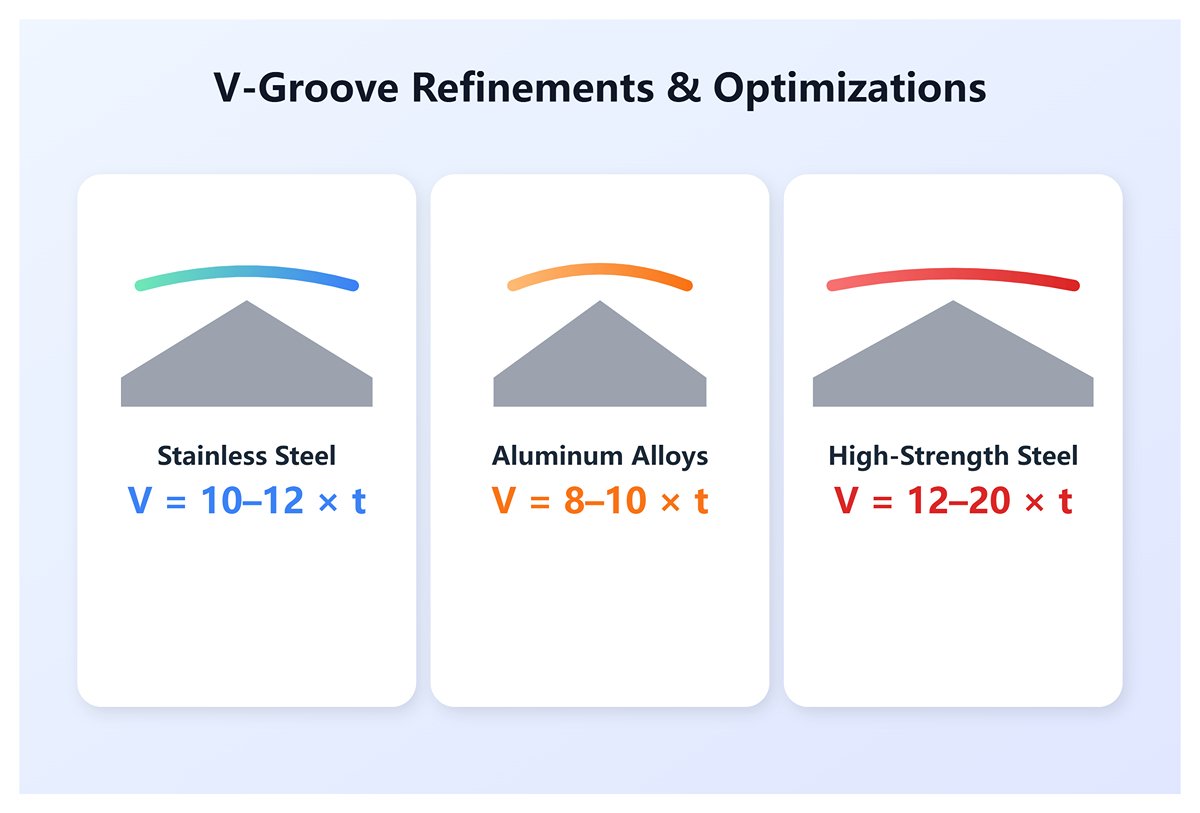
(2) Refinements and Optimizations
- Stainless Steel: With higher yield strength and good ductility, a wider V-groove is needed—typically V = 10–12 × t—to reduce bending stress, prevent cracking, and allow sufficient space for springback.
- Aluminum Alloys: Because the material is soft and prone to indentation at the V-groove shoulders, a slightly narrower width is recommended, V = 8–10 × t.
- High-Strength Steel: Due to very large bending forces, extra-wide grooves—V = 12–20 × t—are necessary to properly distribute stress.
(3) The Insider’s Insight
A narrower V-groove → requires greater tonnage, yields a smaller inner bend radius, and results in less springback;
A wider V-groove → requires less tonnage, yields a larger bend radius, and produces more springback.
Selecting a V-groove is essentially about finding the best balance among tonnage, bend radius, and springback.
6.3.3 Tonnage Calculation and Safety Margin: Prevent Overload and Protect Equipment and Dies
Estimating the required tonnage before each bend is essential for safety and for prolonging equipment life.
(1) Empirical Formula (Free Bending, Low-Carbon Steel)
P = (650 × t² × L) / V
P is the required tonnage, t the sheet thickness, L the bend length, and V the V-groove width.
(2) Safety Margin
The calculated value represents the minimum required force—never operate your machine at 100% of its rated capacity. Always keep at least a 20% safety margin. For instance, if the calculation yields 80 tons, using a 100-ton machine is a safe and reasonable choice.
(3) Critical Mistake
Overloading can damage not only the hydraulic system and frame but more often the punch tip itself. Under excessive pressure, the punch tip may chip or permanently deform. Protecting your costly tooling starts with never exceeding load limits.
6.3.4 Die Installation and Alignment: Fine-Tuning for Micron-Level Accuracy
What seems like a simple installation step actually hides the crucial details that determine final bending precision.
(1) Cleanliness Is Everything: Before installation, thoroughly clean the die mounting surfaces, worktable, and upper die holder using a soft, lint-free cloth and compressed air. Even a single metal chip can cause misalignment and lead to deformation of the entire workpiece.
(2) Secure Installation: Follow the proper procedure to mount the dies and ensure all clamping devices—manual, pneumatic, or hydraulic—are fully locked.
(3) Precise Alignment: Make sure the centerlines of the upper and lower dies coincide perfectly over the entire length.
- Traditional Method: Slowly lower the ram until a sheet of paper just fits between the dies. Check if the paper is evenly gripped along the full length.
- Professional Method: Use dedicated alignment tools or laser alignment systems for fast and precise calibration.
- Pro Tip: A mere 0.1 mm of misalignment can cause an angular deviation beyond tolerance on a 3‑meter-long workpiece. Don’t trust your eyes—trust your tools and data.
6.3.5 Die Lifecycle Management: From Routine Maintenance to Regrinding and Restoration
Dies are consumables, but proper management can greatly extend their optimal service period.
- Routine Maintenance: After each use, clean the dies and apply a thin layer of rust preventive oil. Store them on dedicated racks to prevent collision or stacking damage.
- Wear Detection: When you notice scratches on workpieces or increasing bend angle compensation, it usually indicates that the shoulder radius of the lower die’s V-groove has enlarged from wear—this is the most common form of die degradation.
- Repair and Regrinding: Never attempt to reshape a die with a handheld grinder, as this will ruin its precision and heat-treated surface. Always send it back to the manufacturer or a professional die restoration service for precision regrinding, ensuring that its height and accuracy are fully restored.
- Record Keeping: Create a usage log for each critical die, recording purchase date, operating hours, and regrind count. This helps predict end-of-life cycles and plan replacements in advance, avoiding costly production interruptions.
In summary, a profound understanding of both machine and die systems forms the essential bridge between theory and practice. It transforms you from a passive operator into a true expert—capable of optimizing setups, anticipating risks, and unlocking the full potential of your tools for every unique task.
Ⅶ. The Five Core Operational Steps: Reproducing the Perfect First Piece from Scratch
Having mastered the theoretical foundations and equipment selection, we now reach the heart of bending craftsmanship—hands-on operation. Mastery doesn’t rely on vague “feel” or guesswork, but on a precise, scientific, and repeatable process. This “Five-Step Core Operation Method” distills the wisdom of countless top sheet‑metal artisans, guiding you to systematically control every variable and ensure that every product—from the first prototype to full‑scale production—meets flawless standards.
7.1 Step One: Process Planning and Sequence Simulation — “See the Final Part in Your Mind, Control the Process with Your Hands”
Before you even touch the machine, the true work begins in your mind. This stage forms the foundation of the entire bending process and determines efficiency, precision, safety, and ultimately the success of the final product. The operator must move beyond the two-dimensional drawings and mentally construct a full three-dimensional model of the finished part, planning the optimal manufacturing sequence.
(1) Systematic Thinking Based on the “Golden Triangle”
Exceptional process planning begins with a holistic assessment of three core elements: the machine, the tooling, and the material.
- Machine: Understand your press brake’s tonnage, accuracy, throat depth, number of back gauge axes, and deflection compensation capability. These parameters define what is feasible and what is not.
- Tooling: Select the correct upper and lower dies based on material thickness, strength, and desired bending radius—this is essentially the “brushstroke” that shapes geometry.
- Material: Be familiar with the type of material (e.g., cold-rolled steel, stainless steel, aluminum), precise thickness, yield strength, and rolling direction. These determine springback predictions and crack prevention.
Simulating the Bending Sequence
The bending sequence is the core of process planning. An incorrect sequence may cause interference between the part, machine, or tooling, preventing subsequent operations and leading to scrap.
- Inside-Out Approach: For closed or semi-closed shapes such as box components, bend the inner short edges first, then the outer long ones to prevent obstruction in later steps.
- Short Before Long: Bend shorter flanges before longer ones to ensure adequate space and avoid interference.
- Avoid Collisions: Simulate each bending operation mentally or using offline software to check for interference among the part, tools, back gauge, and machine.
- Plan Rotations and Flips: Complex parts often require clever flipping or rotation. Proper planning can solve seemingly impossible challenges.

Pro Tips
- Mind the Grain Direction: Bending lines should ideally be perpendicular to the rolling direction (cross-grain bending) for a smaller radius and reduced risk of cracking. Consider the grain orientation during blank layout.
- Minimum Flange Principle: A flange must be wide enough to rest stably on the lower die. As a general rule, the inner flange length should be at least half the width of the V-opening plus the material thickness. Otherwise, the piece may slip, causing dimensional errors and safety hazards.
7.2 Step Two: Parameter Setting and Program Initialization — Mastering Control at the Panel
This step transforms your process blueprint into precise, machine-executable instructions. The CNC press brake’s control system acts as its “brain,” and parameter accuracy directly determines the quality of the first part.
Core Parameter Entry and Retrieval
- Program Retrieval: For repeat production, call up verified programs to improve efficiency.
- New Program Setup: For new parts, accurately input all key parameters:
- Material type, tensile strength, and actual thickness;
- Upper and lower die model numbers, punch radius, and V-opening width;
- Bend angles and flange lengths (i.e., back gauge position dimensions).
Leveraging CNC Intelligence
The system can automatically compute bending pressure, Y-axis travel, springback compensation, safety height, and speed transition points. Many systems also support graphical programming—importing 2D or 3D drawings to automatically suggest bending sequences and tooling, minimizing programming errors.
Pro Tips
- Springback Compensation: System-calculated values are theoretical; differences in material batches affect results. Always fine-tune on-site—never rely blindly on data.
- Bending Radius Misconception: In air bending, the actual inside radius depends on the V-opening width (approximately 15%–17%), not the punch radius. Only in bottoming or coining methods does the punch radius directly define the inner radius.
7.3 Step Three: Precision Setup and Calibration — Tool Installation and Back Gauge Alignment
This step bridges the virtual program and the physical machine. Even the slightest installation error will magnify during bending.
Tool Installation and Alignment
- Cleanliness First: Thoroughly clean the dies, worktable, and clamping devices. Residues or dust can compromise precision and leave unwanted marks.
- Secure Fastening: Install and lock both upper and lower dies according to specifications to prevent shifting during operation.
- Accurate Alignment: The centerlines of the upper and lower dies must align perfectly along their full length, checked with laser or scribing blocks. Off-center loading affects bending angles and causes uneven wear.
Back Gauge Calibration
- Multi-Point Verification: Measure the distance from finger stops to the lower die center using a caliper or depth gauge, then compare and calibrate against system values.
- Check Parallelism and Perpendicularity: The back gauge beam should be parallel to the lower die centerline, and stop fingers must be perpendicular to the worktable to avoid dimensional discrepancies.
Pro Tips
- Deflection Compensation Check: For bend lengths over one meter, deflection compensation must be activated. Incorrect settings cause inconsistent angles between the center and ends, creating a “canoe effect.”
- Segmented Die Caution: All segment heights and shoulder lines must match precisely. Otherwise, uneven angles and marks may occur. Using precision-ground dies improves consistency significantly.
7.4 Step Four: Test Bending and Fine Adjustment — The First Piece as the Ultimate Proof
This is the critical test that bridges theory and practice. A passing first piece marks the true beginning of mass production.
Trial Bending Procedure
- Perform test bends using material from the same batch as the final product to ensure valid results.
- Verify key bending steps first before completing the full first piece.
First Piece Measurement and Inspection
- Angle Measurement: Use a precision protractor to measure bend angles at multiple positions, record any deviations.
- Dimensional Verification: Use calipers to confirm flange lengths meet drawing specifications.
- Visual Inspection: Check bent areas for cracks, scratches, or surface defects.
Parameter Fine-Tuning
- Angle Compensation: Adjust system values according to measured deviations so that springback achieves the target angle.
- Back Gauge Adjustment: Fine-tune coordinates to correct flange length variations.
Pro Tips
- Differentiate Error Types: Systematic errors can be corrected through compensation, while random errors require inspection of tooling, back gauge, or operator technique.
- “Reverse Bend” Verification Method: Conduct a counter-bend to test back gauge parallelism—a proven technique for achieving high precision.
7.5 Step Five: Mass Production and Process Monitoring — Making Every Piece as Perfect as the First
Once the first piece passes inspection, the challenge shifts from creation to replication. The goal now is steady, efficient production with consistent quality.
Start Production and Maintain Rhythm
After setting the batch quantity, maintain a stable operating rhythm with consistent feed speed and force. Inconsistent pacing is a common cause of dimensional fluctuation.
Process Monitoring and Statistical Quality Control (SPC)
- Begin–Mid–End Inspection: In addition to full inspection of the first piece, conduct periodic sampling during and after production.
- Watch for Anomalies: Pay attention to machine noise, oil temperature, and pressure changes—these can indicate equipment or tooling issues.
- Real-Time Monitoring Systems: Advanced press brakes can measure angles in real time or use online sensors for full process tracking.

Pro Tips
- Beware of Thermal Drift: Extended operations can cause oil temperature rise and structural deformation, leading to gradual angular drift—periodic micro-adjustments are necessary.
- Batch Consistency Management: Each time new sheet material is introduced, conduct a fresh bending test to verify springback differences — never assume identical performance across batches.
- Tool Wear Effect: Long-term wear affects both angle and radius consistency. Establish a formal die maintenance program to ensure lasting stability and precision.
Ⅷ. Conclusion
Our passage introduces the knowledge of press brake training to guide you to pay attention to professional skills training. It is pivotal for enterprises and employees who use press brake machines to gain comprehensive training, consistent learning, and skill development in the sheet metal industry.
ADH Machine Tool is a press brake manufacturer with skilled workers, professional technicians, and responsible after-sales personnel with more than 40 years experience in the sheet metal industry.
We provide reliable machine training and testing programs as above pictures. If you want to get training on your machine, you can contact us for this free training session or visit the official website for knowledge learning.
Ⅸ. FAQs
1. Where can I find press brake training for beginners?
Beginners can take advantage of technical schools and vocational programs that offer fundamental courses in sheet metal fabrication and machinery operation. Local community colleges often provide these training opportunities. Many manufacturers and industry associations also offer apprenticeships for hands-on experience.
2. What are the costs associated with press brake training programs?
The costs of press brake training programs vary widely. Costs depend on factors like the program's length, location, and the institution providing the training. Community colleges and technical schools may offer more affordable options compared to specialized institutions.
3. How can someone obtain press brake operator certification?
Certification generally involves completing a training course and passing an examination. Industry-recognized bodies or the institution offering the training program may provide certification. It's important for operators to maintain competency and stay updated with continuing education opportunities.
4. Are there any online courses available for press brake training?
Online courses offer flexibility for those interested in press brake training. Various educational platforms and industry-specific websites provide virtual classes with interactive modules. This training session can be a convenient option for learning theoretical principles and safety guidelines.
5. What are the OSHA regulations pertaining to press brake operations?
OSHA mandates safety protocols to minimize the risk of accidents during press brake operations. Key requirements include machine guarding measures, employee training on safety practices, and regular equipment maintenance. Compliance with OSHA standards is crucial for workplace safety.
6. Can you explain the 'rule of 8' in press brake operations?
The 'rule of 8' refers to using a pressing force that should not exceed 8 times the material's thickness to form a part without causing damage. This rule helps operators maintain tool and machine integrity while ensuring precise bending and forming of materials.
7. What safety precautions are essential when operating a press brake?
When operating a press brake, several essential safety precautions must be followed to protect the operator and ensure safe machine use.
First, machine guarding is crucial. Physical guards should be installed around moving parts to prevent accidental contact with pinch points or other hazardous areas. Safety devices such as two-hand controls help maintain a safe distance while the machine is running, ensuring the operator’s hands are not in danger. Light curtains or laser sensors near the dies are also effective at halting the machine if an operator enters the hazardous zone.
Proper operator training is vital. All press brake operators should undergo comprehensive safety training, covering the machine's potential hazards and the necessary precautions. Regular supervision is also recommended to ensure adherence to safety protocols. Additionally, the work area must be kept clean and free of hazards such as scrap materials, oil, and grease, which can cause slips, trips, and falls.
Personal protective equipment (PPE) is another important safety measure. Operators should wear gloves, safety helmets, and non-slip shoes to protect against crushing or sharp edges, while hearing protection should be used to prevent hearing damage from the press brake’s noise.
Operational safety procedures include never leaving the press brake unattended while in use and following proper lockout/tagout procedures during maintenance. The machine should be switched off when not in use, and the workspace should be free from distractions.
Finally, physical safety should not be overlooked. Operators should take care to avoid muscle strain by using proper ergonomics and taking regular breaks. Additionally, when handling large or heavy materials, two-person cooperation may be necessary to ensure safe operation.


