I. Introduction to Shearing Machine Hydraulic System
Shearing machines, a staple in metal processing industries, rely heavily on hydraulic systems to perform their tasks. The efficiency and effectiveness of shearing machines are significantly enhanced by the integration of hydraulic systems, which provide the necessary force and control to execute clean and accurate cuts.
Hydraulic systems use fluid pressure to generate force, allowing for the precise cutting of metal sheets in shearing machines. The primary aim of my article is to provide a comprehensive understanding of the hydraulic systems used in shearing machines. For readers seeking a deeper insight into the fundamentals and applications of this technology, we recommend exploring our Guide to Hydraulic Shearing Machines.
Ⅱ. System Anatomy: A Masterclass on the Core Components and Working Principles of Hydraulic Shears
To truly master a hydraulic shear, simply knowing how to operate it is far from enough. You must, like a skilled surgeon, dive deep into its internal anatomy to understand precisely how each component works in harmony—transforming invisible fluid pressure into tremendous, razor-sharp cutting power. This chapter is your masterclass in mechanical anatomy. We’ll dissect this precision machine piece by piece, allowing every gear, valve, and oil passage to ‘speak’ to you, guiding your evolution from operator to true controller. For a technical comparison of system setups, refer to the Guide to Hydraulic Shearing Machine Specifications.
2.1 Core Principle: Transforming Fluid into Unstoppable Cutting Power (Pascal’s Law in Action)
The awe-inspiring power of any hydraulic system originates from a simple yet infinitely powerful physical law—Pascal’s Law. It states that any pressure applied at one point in a confined, static fluid is transmitted equally and undiminished throughout the fluid and to the walls of its container.
In a hydraulic shear, this principle is brought to life in a remarkable feat of engineering—a true demonstration of “achieving more with less.”
- The Birth and Amplification of Force: Driven by an electric motor, the hydraulic pump (acting as a small-area piston) applies an initial pressure (P) to the hydraulic fluid.
- Flawless Pressure Transmission: According to Pascal’s Law, that same pressure is instantly and evenly transmitted to the much larger surface area of the main hydraulic cylinder (a large piston).
- The Magnificent Release of Power: Because force equals pressure times area (F = P × A), the cylinder’s surface—tens or even hundreds of times larger than the pump piston’s—generates an output force magnified hundreds or thousands of times, even though the system pressure (P) remains unchanged.
This is the secret behind how a hydraulic system can use just a few dozen kilowatts of power to deliver hundreds of tons of force—capable of slicing through thick steel in an instant. It’s not magic; it’s the elegant beauty of physics applied with engineering precision, playing out daily right there on your shop floor.
2.2 Component Deep Dive: Understanding the Critical Roles of Each Element
A high-efficiency hydraulic system functions like a living organism: each component performs its unique role in perfect coordination with the rest. Let’s examine these key players one by one.

- Power Heart: Hydraulic Pump
The pump is the beating heart of the entire system—it transforms the motor’s mechanical rotation into hydraulic energy, the very source of all force. Its selection directly determines the system’s pressure capacity, response speed, energy efficiency, and stability. The following table outlines a “showdown” among the three main pump types:
| Type | Working Principle | Advantages | Disadvantages | Strategic Selection Insight |
|---|---|---|---|---|
| Gear Pump | Two intermeshing gears rotate, squeezing oil from the suction chamber to the discharge chamber to create pressure. | Simple structure, durable, tolerant of oil contamination, very low cost. | High pressure pulsation (affecting precision), relatively low volumetric efficiency, constant output flow (excess flow is diverted via relief valve, causing energy loss). | Ideal for budget-sensitive machines. Commonly used in low-to-medium pressure setups or as an auxiliary power source. |
| Vane Pump | The rotor spins, pushing vanes outward via centrifugal force to form variable working chambers with the stator wall, completing suction and discharge. | Smooth operation, quiet, low flow pulsation, partially variable. | Requires clean oil; lower pressure capacity and shorter lifespan than piston pumps. | A balanced choice for smooth, low-noise mid-pressure systems such as mid-range guillotine shears. |
| Piston Pump | Pistons reciprocate inside a cylinder block, varying chamber volume to draw in and discharge oil. | Top performance: extremely high efficiency, capable of very high pressures, easy to achieve variable flow (on-demand delivery drastically cuts energy use), fast response. | Most complex and expensive; highly sensitive to contamination (needs fine filtration). | The go-to for high-performance, energy-efficient systems—standard in advanced CNC or servo-hydraulic shears, offering supreme precision, speed, and efficiency. |
- The Muscles in Motion: Hydraulic Cylinder
The cylinder is where energy transformation reaches its conclusion—it converts the fluid’s pressure into the powerful linear motion that drives the cutting beam.- Single-Acting Cylinder: Uses hydraulic pressure to move the piston in one direction (typically the downward cutting stroke), with return motion relying on gravity or springs. Simple in structure but slow and uncontrollable in return—now largely obsolete.
- Double-Acting Cylinder: Hydraulic oil acts on both sides of the piston to control both extension (cutting) and retraction (return), providing faster return and precise positioning. It’s the defining feature of modern high-performance shears and the foundation for rapid production cycles.
- The Control Brain: Valve Assembly
If the pump is the heart, valves are the brain and nervous system. They don’t create power but intelligently manage the flow of hydraulic fluid—the machine’s “lifeblood”—to enable both power and precision.- Directional Control Valve: Governs the direction of fluid flow, dictating whether the cylinder extends, retracts, or holds. The solenoid-operated directional valve is the most common type.
- Pressure Control Valve: Acts like a safety regulator, setting and limiting system pressure. The relief valve serves as the ultimate safety guard against overloading, while the pressure-reducing valve ensures lower, stable pressure for specific circuits.
- Flow Control Valve: Adjusts the volume of hydraulic fluid passing through, allowing precise control of cylinder speed—both downstroke and return. In advanced systems, proportional valves and servo valves regulate pressure and flow continuously based on electrical signals, enabling ultra-precise motion control
- Lifeblood and Circulatory System: Reservoir, Hydraulic Fluid, and Cooling System
These elements sustain the machine’s “metabolism” and long-term stability—often underestimated in importance.- Reservoir: Far more than just a storage tank—it also serves to dissipate heat, release trapped air, and settle impurities. A poorly designed tank can be a hidden cause of overheating and oil contamination.
- Hydraulic Fluid: The medium of energy transfer—and also a lubricant, rust inhibitor, and coolant. Its viscosity, cleanliness, and anti-wear properties directly determine as much as 80% of the system’s performance and lifespan.
- Cooling System: During high-load continuous operation, energy loss is converted into heat. The cooler—whether air- or water-cooled—keeps the oil temperature within the optimal range (typically 45–55°C), preventing premature oxidation, viscosity loss, and seal aging.
- System Guardians – Filters, Accumulators, and Sensors: These components are the “protectors” and “senses” of the hydraulic system, ensuring its cleanliness, efficiency, and intelligence.
- Filters: The first line of defense against premature wear of precision valves and pumps. Studies show that over 80% of hydraulic failures stem from fluid contamination. The suction, pressure-line, and return filters together form a multi-layer protection network.
- Accumulators: Think of these as “hydraulic batteries.” They store high-pressure oil when system pressure exceeds demand and release it when needed—for example, during rapid tool return or peak shearing moments—providing peak flow supplementation and pressure shock absorption that dramatically increase system responsiveness and energy efficiency.
- Sensors: Pressure, temperature, and position sensors distributed throughout the system act as its “eyes” and “touch.” They feed real-time data back to the control unit, enabling CNC control, closed-loop regulation, and predictive maintenance.
[Visualization Blueprint]: Standard Hydraulic Circuit Workflow (Guillotine Shear)
Close your eyes and follow a drop of hydraulic oil on its perfect shearing journey:
- Standby Mode: The pump continues to run, but the main directional valve remains centered, allowing low-pressure oil to flow back to the tank. The system stays in a “resting” state with minimal power consumption.
- Rapid Downstroke: Once the command is issued, the solenoid energizes, shifting the valve. High-pressure oil rushes into the upper chamber of the main cylinder. In advanced systems, a differential circuit channels oil from the lower to the upper chamber, combining gravity and hydraulic force to achieve a lightning-fast descent of the cutting beam.
- Working Stroke (Shearing Phase): As the blade engages the sheet, pressure surges instantly. Pressure and flow valves work in tandem to maintain precise control, delivering stable, powerful force for a clean, consistent cut.
- Pressure Hold and Return: At the end of the cut, the system briefly holds pressure to ensure full separation. The directional valve then reverses, sending high-pressure oil into the lower cylinder chamber to drive the blade back up while returning the upper chamber’s oil to the tank. A perfect cycle is complete.
2.3 [Unique Perspective 1] Hydraulic vs. Mechanical Shearing: A Data-Driven Performance Showdown
In the world of shearing machines, the debate between “hydraulic” and “mechanical” camps has persisted for decades. For decision-makers, it’s not just a matter of technology—it’s a strategic choice balancing efficiency, cost, and quality. The following in-depth, data-based comparison reveals the truth beneath the surface. For a deeper dive into this ongoing debate, consider reading Hydraulic vs Mechanical Shearing Machines, which expands on this analysis with practical examples and technical charts.
| Comparison Dimension | Hydraulic Shear | Mechanical Shear | Strategic Insight |
|---|---|---|---|
| Shearing Accuracy & Cut Quality | Extremely high and fully controllable. The hydraulic system easily adjusts shear angle and blade gap to suit different plate thicknesses, minimizing distortion and burrs. The downward force is smooth and shock-free, producing near-perfect edges. | Moderate to high, but less adaptable. The shear angle is typically fixed, and the flywheel’s rigid impact can cause vibration and reduced cut quality on thicker plates. | For high-precision and high-quality cutting (e.g., aerospace, decorative metalwork, precision sheet fabrication), hydraulic shears are unrivaled, directly determining product value and yield rate. |
| Cutting Force & Speed | High, with fully adjustable force throughout the stroke. Effortlessly handles thick plates and high-strength alloys. Moderate cycle rate (15–40 strokes/min) but capable of continuous operation. | Extremely fast, but with fixed cutting force. Ideal for thin sheets with speeds reaching 50–80 strokes/min. However, since the energy is released in one burst, it struggles with thick or hard materials. | Mechanical shears dominate in “thin-sheet, mass-production” scenarios. Hydraulic shears excel in “thick-sheet, varied-material, continuous-production” operations, delivering superior overall efficiency. |
| Total Cost of Ownership (TCO) | Flexible initial investment. A key advantage is built-in overload protection: when cutting force exceeds limits, the relief valve automatically unloads, protecting the machine and blades. Maintenance costs are predictable (oil, filters), and tool life extends 30–50% thanks to smoother load conditions. | Higher upfront cost and minimal routine maintenance, but lack of overload protection is a fatal flaw. A single error—like attempting to cut overly thick material—can catastrophically damage the flywheel, clutch, or frame, leading to costly, lengthy repairs. | From a TCO standpoint, hydraulic shears offer lower and more predictable long-term operating costs. Their overload protection serves as invisible insurance, safeguarding both equipment and investment. |
| Processing Flexibility & Versatility | Exceptional. Adjustable pressure, flow, shear angle, and blade gap enable cutting of thin stainless steel, thick carbon steel, plastics, and composites—achieving true multi-material adaptability. The ideal tool for flexible manufacturing. | Limited. Typically designed for specific thickness ranges; adjustment for different materials is complex and often ineffective, making it unsuitable for small-batch or diverse-product manufacturing. | With unmatched versatility, hydraulic shears are strategic assets in modern manufacturing, enabling agile production and customized solutions in a fast-changing market. |
Ⅲ. The Master Operator: Best Practices for Precision Calibration and High-Efficiency Production
If Chapter 2 was about anatomy, this one is the art of application. Operating a hydraulic shear isn’t just repetitive button-pushing—it’s a craft that fuses rigorous science (calibration) with fluid artistry (rhythm). The operator is both guardian of the machine and creator of efficiency. Master the following time-tested best practices, and you will no longer merely use the equipment—you’ll command it, transforming every ounce of potential into flawless output and tangible profit.
3.1 Pre-Startup “Cockpit” Inspection: Seven Essential Steps for Safety and Precision
Every startup should be treated like a pilot’s pre-flight ritual—a disciplined checklist that safeguards both performance and safety. These few minutes can prevent nearly 90% of unplanned downtimes and accidents. Commit these seven steps to muscle memory, and approach each with zero tolerance for negligence.
Environment Check & Visual Inspection
Ensure the area within 3 meters of the machine is clear of debris, oil, and obstacles. This isn’t just about preventing slips and trips—it secures an unobstructed evacuation path in emergencies. Next, visually inspect the machine for any loose bolts, cracked welds, or oil stains at hydraulic joints—early signs of leakage.
- Verification of Personal Protective Equipment (PPE):
This is not a recommendation—it’s a command. Check and put on properly fitted workwear, steel-toed safety shoes, and impact-resistant safety glasses. Pay particular attention to ensuring there is zero risk of entanglement: do not wear gloves (except when operating the control panel), watches, rings, or any jewelry. Long hair must be securely tied and tucked inside a work cap. - Functional Verification of Core Safety Devices:
This is a non-negotiable red line. Manually trigger each safety mechanism at least once, including but not limited to:
Photoelectric Protection Device
Test with your hand or an object to confirm the blade movement stops instantly.
- Guard Door Interlock:
Open the safety gate and verify that the machine cannot be started. - Emergency Stop Buttons:
Press each one—on the control panel and on the machine body—to confirm that power is completely and immediately cut off. Never, under any circumstances, short-circuit or bypass a safety device for the sake of convenience.
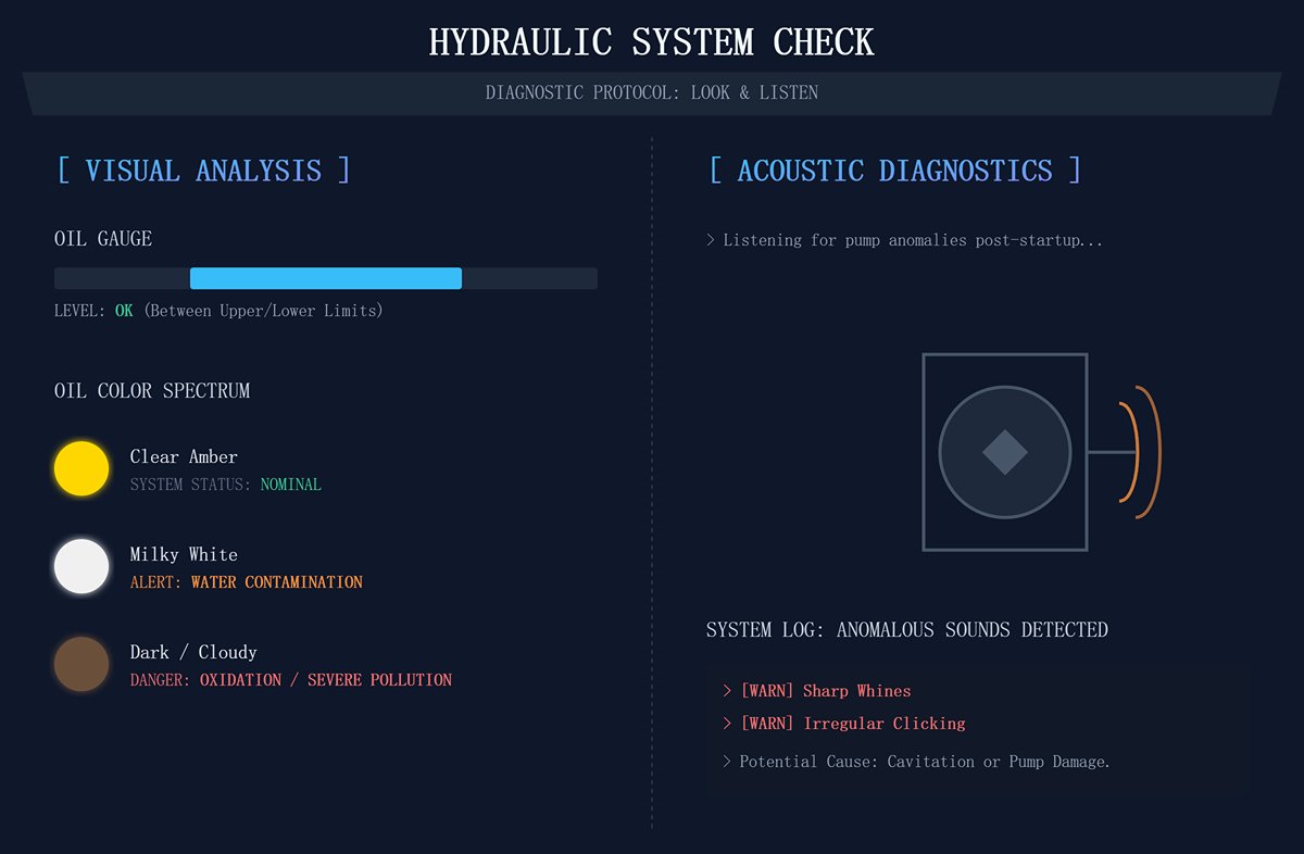
Hydraulic System Check—“Look, Listen, Feel, and Smell”
- Look: Inspect the oil gauge to ensure the level is between the upper and lower limits. Observe the oil color—clear amber is ideal. Milky white indicates water contamination; dark or cloudy suggests oxidation or severe pollution—both are major warning signs.
- Listen: After startup, stand near the pump and listen carefully for sharp whines or irregular clicking—these can be early indicators of cavitation or pump damage.
- Blade Condition Inspection: Examine the upper and lower blades closely from multiple angles. Look for chips, rolled edges, or fine cracks. A compromised blade doesn’t just tear sheet metal and create burrs; under high stress, it can fracture catastrophically.
- Back Gauge and Worktable Inspection: Confirm that the back gauge moves smoothly and that the worktable is free of metal debris or raised spots, which can distort positioning accuracy and scratch sheet surfaces.
- No-Load “Warm-Up” Cycle: Before feeding any material, let the machine run idle at medium speed for two to three complete cycles. This dynamic “full-body check” allows you to sense the smoothness of blade travel, detect any abnormal noises in the hydraulic system, and confirm proper coordination of all moving parts.
3.2 Calibration Guide: The Path to Perfect Shearing
Accurate calibration is the soul of precision cutting. It determines whether the edge is mirror-smooth or covered with burrs, whether it’s straight as a line or warped and twisted. The following three core calibrations are your essential steps from simply “being able to cut” to “cutting beautifully.”
- Step One: Setting the Blade Gap — The Deciding Factor for Burrs and Blade Life
The blade gap refers to the minute vertical overlap or distance between the upper and lower blades. It is the most critical and frequently adjusted calibration parameter.- Golden Rule: The ideal gap is a function of the material thickness. A proven empirical formula is:
| Material Type | Recommended Gap (as % of Material Thickness) |
|---|---|
| Low-Carbon Steel | 7% - 10% |
| Stainless Steel | 5% - 7% |
| Aluminum Alloy | 8% - 12% |
Example: When shearing 6 mm stainless steel, the ideal gap is 6 mm × 6% = 0.36 mm.
- The Cost of Error:
- Gap Too Small: The sheet is “crushed” rather than “cut,” causing secondary shearing with a shiny but compressed edge. This dramatically increases cutting force, accelerates blade wear, and spikes hydraulic pressure.
- Gap Too Large: The sheet is “torn” instead of cleanly cut, producing heavy burrs, rolled edges, and distortion. The rough edge makes the piece unsuitable for precision assembly.
- Calibration Method: Always use a feeler gauge to measure and fine-tune at least three points—left, center, and right—along the blade length, ensuring uniform clearance.
Expert Tip: Shine a flashlight from behind the blades; the consistency of the light gap reveals alignment quality in seconds. - Step Two: Adjusting the Rake Angle — The Art of Balancing Flatness and Force
The rake angle is the incline of the upper blade relative to the horizontal plane. It creates a “scissor effect,” serving as a strategic balance between cutting force and material deformation.- Core Function: Reduces cutting force. Because the entire blade doesn’t engage the sheet at once, peak force is significantly lowered.
- Optimization Guidelines:
- For thin sheets (< 6 mm): Use a smaller rake angle (around 0.5° – 1.5°). This minimizes bowing and twisting, ensuring exceptional flatness—critical for high-precision sheet metal work.
- For thick sheets (> 10 mm): Use a larger rake angle (about 2° – 3°). This significantly reduces the load on the hydraulic system, allowing it to shear thicker materials efficiently under lower pressure.
- Step Three: Programming the Back Gauge — Achieving Flawless Repeatable Precision
The back gauge is the ultimate authority on dimensional accuracy. Its precision determines the consistency and qualification rate of every batch produced.- Key Performance Metrics: Focus on two values—positioning accuracy (whether it truly reaches 100.00 mm) and repeatability (whether each return to 100.00 mm stays within ±0.05 mm). The latter matters most in mass production.
- Calibration and Confidence: Periodically (e.g., weekly) measure the true back gauge position with a calibrated steel tape or digital caliper, comparing it with the CNC’s displayed value, then apply compensation as needed. Once calibration is complete, you must trust the CNC system fully. Automated, rapid, and precise positioning eliminates human measuring errors and drastically boosts production rhythm.

3.3 Efficiency-Boosting Techniques: Pressure Optimization and Rhythm Coordination for Energy Savings
Efficient production forms the “iron triangle” of speed, quality, and cost. A master operator knows how to strike the perfect balance among the three.
Smart Pressure Optimization: Never let the pressure gauge needle “run into the red.” Setting system pressure to the maximum is both wasteful and harmful. The correct approach is to adjust the working pressure according to the specific task (material type and thickness) until it reaches the level that delivers a clean, crisp shear, then increase it by only 10–15% as a safety margin. This method offers multiple benefits:
- Significant Energy Savings: Energy loss in hydraulic systems is directly proportional to pressure.
- Temperature Control: Lower pressure means less conversion of energy into heat, extending the lifespan of hydraulic oil and seals.
- Longer Component Life: Pumps, valves, and cylinders experience exponentially reduced wear and fatigue when operating under lower pressure.
- The “Dance Rhythm” of Human-Machine Coordination: Treat feeding, positioning, cutting, and discharging as one continuous, optimizable “human-machine cycle.” A skilled operator should move like a dancer flawlessly synchronized with the machine’s rhythm — anticipating each motion with precision. While the blade frame is swiftly returning, the operator should already begin pushing and roughly positioning the next sheet. As the frame comes to a full stop, the sheet should precisely align with the back gauge. Such seamless coordination can boost actual productivity by more than 20% without changing the machine’s inherent cycle speed.
3.4 Safety Red Line: Mandatory Pressure Protection and Emergency Shutdown Protocols
On the path to efficiency, safety is the one line that must never be crossed. Ignoring the following protocols is equivalent to putting both yourself and expensive equipment at serious risk.
Pressure Protection: The System’s “Final Safety Fuse”
- Identification and Understanding: Locate the system’s Pressure Relief Valve (PRV). This is not an operating valve, but rather the system’s guardian. Its sole purpose is to immediately open when system pressure abnormally spikes beyond its set limit (caused by factors such as cutting overly thick material or dull blades). The valve then directs high-pressure oil back to the tank, preventing the pump, piping, and cylinders from catastrophic failure.
- Setting Restrictions: The relief valve’s pressure setting must be configured and sealed by authorized technical personnel using a calibrated pressure gauge. Typically, it is set at 110%–125% of the system’s maximum working pressure, but must never exceed 90% of the rated pressure of the pump or the weakest component. Operators are strictly forbidden from increasing this setting to cut thicker plates — this is one of the leading causes of fatal equipment damage.
- Emergency Stop: The Decisive Lifeline
- Activation Timing: In any of the following situations, you must overcome hesitation and instinctively hit the nearest emergency stop button without delay:
- Function and Reset: The emergency stop button cuts off all control and power supplies at the highest priority, halting all moving parts instantly. Once pressed, it remains locked in place.
- Restart Procedure: Before resetting (usually by twisting or pulling) the emergency stop button, you must thoroughly investigate and resolve the root cause of the stop. Only once the issue is fixed and everyone is confirmed safe should the system be reset and restarted. Never attempt the dangerous “press-reset-retry” shortcut.

Ⅳ. The Preventive Maintenance Bible: From Zero Unplanned Downtime to Rapid Fault Diagnosis
In the precision-driven world of manufacturing, any unplanned shutdown is a harsh discord in the symphony of efficiency. It devours profits, delays deliveries, and erodes reputation. The hydraulic system — the very heart of a shear machine — is often the source of such disruption. And a harsh truth remains: over 80% of hydraulic failures arise not from component wear-out, but from preventable maintenance neglect.
This chapter is your operational scripture for achieving zero unplanned downtime. It marks an end to the reactive “fix it when it’s broken” cycle and establishes a foolproof preventive maintenance framework — from daily inspections to expert-level predictive analysis. This system isn’t a cost; it’s the highest-return insurance your factory can invest in.
4.1 Preventive Maintenance Playbook: Structured Service Schedule
Successful maintenance begins with discipline. Implement the following schedule — distilled from leading global factory practices — as your workshop’s Standard Operating Procedure (SOP) and enforce it with unwavering authority.
- Daily 5-Minute “Cockpit” Inspection Checklist (Operator Responsibility)
- Visual Inspection and Cleaning: Check the oil tank level gauge to confirm proper oil level. Quickly scan all hydraulic lines, fittings, and cylinders for early signs of oil stains or leaks. Keep the area around the machine clean and free of oil.
- Auditory Diagnosis: When the machine starts, listen carefully for high-pitched whining (a sign of cavitation) or irregular knocking. Report any noise that deviates from normal operation immediately.
- Temperature Awareness: Using the back of your hand (with safety precautions) or an infrared thermometer, check the temperature of the tank, pump housing, and main valve block. Excessive heat is a clear warning of system overload.
- Safety Function Test: Before the first start-up each day, verify that photoelectric guards, safety door interlocks, and emergency stop buttons are functioning perfectly.
- No-Load Cycle Test: Run 2–3 no-load shear cycles to ensure smooth blade frame motion with no hesitation or vibration.
- Weekly Core Component Checkpoints (Maintenance Technician Responsibility)
- Filter Condition Check: Examine the differential pressure indicator or warning light on the return and pressure filters. If the indicator enters the red zone, the element is clogged and must be replaced immediately.
- Cooler Efficiency Inspection: Clean dust and oil buildup from the fins of air-cooled heat exchangers and check water flow in water-cooled units. A clogged cooler is the number-one cause of system overheating.
- Critical Bolt Tightening: Inspect and torque fasteners securing hydraulic pumps, motors, and valve assemblies. Vibration is a silent destroyer that causes leaks and loosening.
- Quarterly/Annual Deep Service and System Flushing (Professional Maintenance Team)
- Hydraulic Oil Sampling and Analysis: Every quarter or 2,000 operating hours, take an oil sample and send it for laboratory testing. This is the cornerstone of predictive maintenance (see Section 4.2).
- Mandatory Filter Replacement: Even if the differential indicator hasn’t triggered, replace all filter elements per manufacturer recommendations (typically every 500–1,000 hours) or at least semiannually. Prevention always beats repair.
- Accumulator Pressure Check: Measure the precharge pressure of the accumulator’s nitrogen gas. Low pressure leads to sluggish system response and increased shock loads.
- System Flushing (as required): If oil analysis indicates severe contamination or major hydraulic components (such as pumps) have been replaced, a complete professional flushing is essential to remove all residue and deposits.
- Hose Inspection and Preventive Replacement: Inspect all hydraulic hoses thoroughly for bulges, cracks, wear, or corroded fittings. For hoses in high-pressure or frequent-motion areas, follow manufacturer guidelines for preventive replacement (typically every 2–3 years).
[Actionable Resource]: We strongly recommend creating a visual TPM Equipment Inspection Sheet based on the above checklist and displaying it beside each machine. Have operators and maintenance staff sign off daily and weekly to assign clear responsibility and transform abstract maintenance policies into concrete, habitual practice.

4.2 Hydraulic Oil Management: The Number-One Factor Determining System Longevity
If the hydraulic system is the machine’s heart, then hydraulic oil is its lifeblood. The quality of that blood defines the heart’s health and lifespan. Neglecting oil management is slow mechanical suicide.
- How to Select the Perfect Hydraulic Oil? (Viscosity, Additives, Anti-Wear Grade)
- Viscosity—The First Rule of Thumb:
Always follow the equipment manufacturer’s recommended ISO VG grade (for example, VG46 or VG68). If the viscosity is too high, flow resistance increases, leading to excess heat and cavitation in the pump. If it’s too low, the oil film becomes ineffective, resulting in internal leakage and severe wear. - Choose the Right Type:
For high-performance hydraulic shearing machines, only use premium anti-wear hydraulic oils (AW-type). These contain additives such as zinc dialkyldithiophosphate (ZDDP) that form a protective layer on high-pressure contact surfaces, dramatically extending the service life of pumps and valves. - Cleanliness Is Everything:
Pay attention to the oil’s cleanliness grade (ISO 4406 code) even when purchasing new oil. Introducing “dirty oil” into a clean system is like poisoning its bloodstream. - The Art of Oil Analysis: When to Test and How to Read Reports
Oil analysis is the only true way to “converse” with your hydraulic system—it reveals early warning signs that the naked eye can never catch. - When to Test:
Conduct the first analysis after 500 hours of operation for new systems. Afterward, test quarterly under heavy-duty conditions and every six months under normal loads. Take a sample immediately if you notice overheating, unusual noise, sluggish response, or any irregular behavior. - How to Interpret the Report
- Particle Count (ISO 4406): This is the most critical indicator. The three numbers represent particle levels exceeding 4µm, 6µm, and 14µm. Each level increase means the contamination has doubled. It’s the main culprit behind valve seizure and pump wear.
- Water Content: Once water exceeds 500 ppm, the oil begins to emulsify, drastically reducing lubrication performance and causing rust and corrosion.
- Elemental Analysis: The presence of metals such as copper (Cu), iron (Fe), or aluminum (Al) pinpoints exactly which component is wearing out. For example, rising copper levels often indicate slipper wear in a piston pump.
- Total Acid Number (TAN): A rising acid number signals oxidation and oil degradation. Once the TAN hits the warning threshold, replace the oil immediately—even if it looks clean.
- Standardized Video Guide for Replacing Hydraulic Oil and Filters
Replacing hydraulic oil isn’t just about draining the old and pouring in the new. A complete procedure should include: draining old oil → cleaning the reservoir → replacing all filters → refilling with new oil (using a filtered filling pump) → air purging → no-load cycling → checking oil levels. We highly recommend filming this as a standardized training video to ensure every oil change is executed flawlessly.
4.3 [Ultimate Tool] The Fault Diagnosis Matrix: Your Fast Track from Symptoms to Solutions
When a malfunction occurs, time equals money. This diagnostic matrix serves as your “navigation map,” helping you quickly identify root causes amidst confusing symptoms. Print it and post it inside the control cabinet door for quick access.
| Common Symptoms | Three Most Probable Causes | Diagnostic and Corrective Steps |
|---|---|---|
| Slow/Weak Shearing | 1. Insufficient system pressure 2. Internal pump wear 3. Internal leakage in main cylinder or control valve | 1. Check pressure gauge: connect to the test port and compare with set pressure. If it’s low, inspect and adjust the relief valve. 2. Perform flow testing: connect a flowmeter in series at the pump outlet and compare to rated flow. If it’s below 85% of nominal, the pump is severely worn and needs repair or replacement. 3. Conduct a holding test: raise the blade frame to the top, shut off the main motor, and observe for pressure drop or drift. If it drifts, the cylinder seals are damaged; if pressure drops without movement, the control valve is leaking internally. |
| System Overheating | 1. Cooling system failure 2. Relief valve continuously open 3. Incorrect oil viscosity | 1. Inspect cooler: clean air-cooled fins; for water-cooled types, check inlet/outlet temperature difference—small differences mean blockage or low water flow. 2. Check the relief valve using a stethoscope or infrared thermometer—if it’s noisy or hot during idle, it’s stuck or misadjusted, wasting energy as heat. 3. Verify oil grade: ensure viscosity matches equipment specs; too high or too low increases heat generation. |
| Abnormal Noise/Vibration | 1. Pump drawing in air 2. Misaligned coupling 3. Loose piping | 1. Check suction line: verify oil level, tighten all joints and flanges, and ensure no air leaks; inspect and clean suction filters. 2. Check motor–pump alignment: stop the system, measure coaxiality, and realign if necessary; inspect flexible coupling buffers. 3. Inspect piping during operation: locate high-vibration segments and tighten or add clamps. |
| Oil Leakage | 1. Aged/damaged seals 2. Loose fittings or failed O-rings 3. Scratched piston rod surface | 1. Identify and replace: find the leak source and replace the affected seal (cylinder seal or valve block seal). Use correct material and size. 2. Torque fittings properly: tighten with a torque wrench; if leaks persist, replace the O-ring or sealing cone. 3. Inspect moving parts: examine cylinder rods for scratches or plating damage. Minor scratches can be polished; severe damage requires rod replacement. |
4.4 [Expert Insight 2] Beyond the Manual: Predictive Fault Detection Techniques
True experts don’t wait for failures to occur. They apply advanced tools and predictive thinking to eliminate faults while they’re still in their earliest stages.
- Using Handheld Pressure and Flow Meters to Pinpoint Root Causes These instruments are the diagnostic “stethoscopes” of professional maintenance engineers. When the system feels weak, don’t guess—measure. Connect pressure and flow meters at multiple points in the hydraulic circuit (pump outlet, before valve, cylinder inlet). By testing section by section—like slicing a sausage—you can precisely determine whether the problem lies in the power source (pump), control stage (valve), or actuator (cylinder), thereby avoiding costly and ineffective trial-and-error replacements.
- Using Thermal Imaging to Instantly Detect Overheated Components and Hidden Internal Leaks A handheld infrared thermal camera is your most efficient “non-contact weapon” for diagnosing hydraulic systems. After 15 minutes of operation, scan the entire hydraulic station. Any abnormal “hot spot” points directly to a problem:
- Overheating in Relief or Pressure-Reducing Valves:
Indicates unnecessary throttling or unloading, where high-pressure energy is being wasted as heat. - Unusually Hot Filter Housings:
Clearly signals filter blockage—oil is struggling through the bypass valve and generating throttling heat.
- Overheating in Relief or Pressure-Reducing Valves:
- Abnormally high temperature on a specific valve within a manifold block:
This is most likely caused by internal leakage, where high-pressure oil is seeping through tiny gaps into a low-pressure zone.
Thermal imaging technology reveals otherwise invisible energy losses and hidden internal leaks, making them clearly visible on the screen.
Ⅴ. Performance Optimization and Future Upgrades: Maximizing Your Return on Investment
Mastering a hydraulic shear goes beyond achieving efficient operation and trouble-free performance today—it requires a strategist’s mindset to envision and drive its continuous evolution. The full lifecycle value of a machine isn’t fixed at the time of purchase; it’s continuously reshaped and elevated through every smart optimization and forward-looking upgrade.
In this chapter, we’ll shift our focus from the microscope to the telescope—exploring how advanced technologies and strategic thinking can transform your hydraulic shear from a passive production tool into a strategic asset that continuously adds value and generates new profit. This is not just a technical upgrade—it’s an elevation of investment philosophy.
5.1 Cutting Costs and Boosting Efficiency: Three Advanced Strategies for Energy and Performance Optimization
Traditional fixed-displacement hydraulic systems operate like engines that never shut off—during standby, loading, or other idle phases, the motor and pump keep running at full speed, wasting valuable electricity by converting it into heat and noise. Under today’s energy costs and environmental expectations, such inefficiency is unacceptable. The following three strategies aim to fundamentally reengineer system energy logic, delivering immediate and measurable cost and performance gains.
- Strategy 1: ROI Analysis for Upgrading to Variable Displacement Pumps or Servo Systems — This is the most profitable and impactful energy-saving approach currently available for hydraulic system upgrades.
- Operating Principle: It completely overturns the outdated concept of constant motor speed. In servo-driven or electro-hydraulic proportional variable pump systems, the motor and pump speed (or displacement) adjust in real time—within milliseconds—to match actual process stages such as rapid approach, cutting, pressure hold, return, or standby. During idle or low-load periods, the motor speed can nearly drop to zero, bringing energy consumption close to zero as well.
- In-Depth ROI Analysis:
- Remarkable Energy Savings: Depending on the machine’s load cycle (particularly standby proportion), servo-hydraulic systems can reduce power consumption by an impressive 40%–90%. For companies facing high electricity costs or operating at high utilization rates, the savings are substantial.
- Ultra-fast Payback Period: While initial investment costs are higher, in typical industrial applications, the additional expense is usually recovered within 12 to 24 months through electricity savings alone. After that, every kilowatt-hour saved goes straight to profit.
- Additional Key Benefits:
- Reduced Thermal Management Costs: With dramatic reductions in wasted energy, system heat generation drops by over 50%. This can allow for smaller—or even eliminate the need for—large cooling systems, further cutting equipment and maintenance costs.
- Extended Lifespan and Environmental Benefits: Lower oil temperatures slow oxidation rates significantly, extending hydraulic fluid life by 50%–100%. Seals also last longer without exposure to extreme heat. Meanwhile, average system noise levels can drop by 10–20 dB, improving workplace conditions and employee satisfaction.
- Strategy 2: Using Accumulators for Fast, Energy-Efficient Peak Cutting — The accumulator acts as a “hydraulic battery,” ideal for managing intermittent, high-flow demands in equipment with uneven load curves, such as shearing machines. It’s a clever, high-impact solution that delivers big results with minimal complexity.
- Operating Principle: During non-cutting periods (loading or positioning), the hydraulic pump stores excess energy in the form of high-pressure oil within the accumulator. When rapid return or peak cutting power is needed, the accumulator discharges in parallel with the pump, supplying a surge of flow far exceeding the pump’s own capacity.
- Strategic Advantages:
- System Downsizing and Cost Reduction: Allows designers to use smaller motors and pumps to meet peak demands, directly reducing equipment cost and installation footprint.
- Breaking Speed Limits: By quickly supplementing oil flow during critical phases (especially during ram return), auxiliary time is reduced by 10%–20%, increasing output per unit of time.
- Built-in Damping Function: As an elastic component, the accumulator also absorbs pressure spikes and hydraulic shocks, protecting valves and piping, and significantly extending system lifespan.
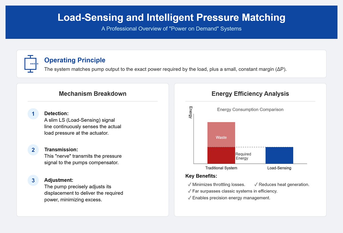
- Strategy 3: Load-Sensing and Intelligent Pressure Matching — If a servo system is about “speed on demand,” load-sensing is about “power on demand.” It is an even more refined approach to intelligent energy efficiency.
- Operating Principle: The load-sensing system uses a slim signal line (the LS line) that acts like a nerve, continuously detecting and transmitting the actual load pressure at the actuator (main cylinder). A pressure compensator within the system then adjusts the pump displacement so that the output pressure is just slightly—by a constant margin (ΔP, typically 15–30 bar)—above the load requirement.
- Energy-Saving Logic: The pump no longer rushes to maintain a fixed maximum pressure like in traditional systems. Instead, it operates like an experienced driver—delivering just enough power with a slight margin for efficiency and stability. This means the system provides only the power required, minimizing throttling losses and heat generation. In terms of energy efficiency, it far surpasses classic pressure-compensated systems, marking a key step toward precision energy management.
5.2 [Case Study] Real-World Success Stories from the Manufacturing Floor
Theory finds its true value only when tested in the furnace of real-world application. The following two factory-based case studies present undeniable data illustrating the tremendous business impact of these optimization strategies.
- Case 1: How a Precision Metalworking Plant Reduced Downtime by 40% Through a Proactive Oil Analysis Program — Facing frequent hydraulic failures, high maintenance costs, and delivery delays, a precision sheet metal manufacturer decided to end its reactive “fix it when it breaks” approach. They invested in a proactive preventive maintenance strategy centered on oil condition analysis.
- Action Plan:
- Establish Health Records: Create detailed maintenance and fault history logs for each critical hydraulic shear, along with a baseline oil analysis to define the system’s initial health status.
- Implement Regular “Health Checkups”: Conduct quarterly oil sampling and send it to a professional lab for analysis of particle contamination levels, moisture content, total acid number, and key wear metals.
- Action Plan:
- Data-Driven Decision Making: If oil contamination or wear elements (such as copper or iron) show an upward trend beyond acceptable limits—even before any visible symptoms appear—immediately activate the contingency plan. This includes scheduling offline circulation filtration, replacing high-precision filters, or using thermal imaging instruments to locate and repair potential internal leakage points.
- Quantified Results: In the first year of implementing this strategy, the company’s unplanned downtime from hydraulic failures dropped by 40%. More significantly, by preventing catastrophic damage to key components (such as plunger pumps), annual repair and spare-part costs decreased by nearly 60%. Every dollar invested in oil analysis generated more than tenfold returns.
- Case 2: Quantitative Report on Cost Savings and Efficiency Gains After Upgrading a Servo Hydraulic System in an Auto Parts Plant
A component manufacturer serving the new energy vehicle sector upgraded a key aluminum sheet blanking line from a conventional hydraulic shear to a fully closed-loop servo hydraulic system to meet increasingly tough demands for cost efficiency and productivity. - Background: The original fixed-displacement pump system consumed excessive power during frequent short idle periods, and oil temperature alarms were common in summer, often interrupting production.
- Quantitative Results Report:
- Energy Costs: Post-upgrade, power meter readings showed that the machine’s overall energy consumption dropped by more than 65% on a typical working day. This single improvement translates into annual electricity savings worth tens of thousands of dollars.
- Production Efficiency: The servo system’s exceptional responsiveness and precise positional control boosted both the stroke return speed of the blade frame and the backgauge positioning speed. As a result, the cycle time per cut was reduced by 18%, directly increasing the line’s throughput capacity.
- Quality and Maintenance: With smoother and more accurate pressure control, batch consistency in cutting performance improved markedly. Meanwhile, system oil temperature remained steady at around 45°C, allowing the oil replacement cycle to extend from one year to two, achieving dual savings in maintenance costs and downtime.
5.3 [Unique Perspective 3] Embracing Industry 4.0: Integrating Your Hydraulic System into Smart Manufacturing
Tomorrow’s competition will be between ecosystems, not individual machines. Your hydraulic system will no longer serve merely as an isolated power source on the production line—it must evolve into an intelligent node capable of sensing, reasoning, and communicating within a connected smart manufacturing environment.
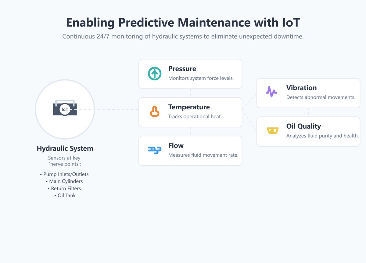
- How IoT Sensors Enable Predictive Maintenance and Eliminate Unexpected Downtime
This is not science fiction. By installing cost-effective wireless sensors at key “nerve points” of the hydraulic system (such as pump inlets and outlets, main cylinders, return filters, and the oil tank), you can enable continuous 24/7 monitoring of critical parameters—pressure, temperature, flow, vibration, and oil quality.
- A Revolution in Maintenance Practices
The vast amounts of collected data are uploaded to a cloud platform, where advanced AI algorithms perform deep analysis. Maintenance no longer follows a fixed calendar but adapts to the system’s real-time health condition—shifting from scheduled servicing to condition-based or predictive maintenance. For example, when the algorithm detects early bearing wear through vibration spectrum analysis, it can issue a warning weeks in advance and automatically generate a maintenance work order with a complete spare-part list in your CMMS (Computerized Maintenance Management System). This marks the ultimate leap from preventive to predictive maintenance. - Using Data Analytics to Optimize Cutting Parameters in Real Time and Improve Yield
Every shearing operation produces valuable process data. By recording parameters such as actual pressure and speed curves, blade gaps, and correlating them with output metrics like burr size or plate deformation, you build a powerful self-learning process database. - Application Scenario
Through machine learning, the system can autonomously identify and store the optimal cutting “recipes” for materials of different types and thicknesses. When the operator scans a barcode from a new batch, the system automatically recommends or loads the best parameters—minimizing trial-and-error costs and achieving top yield and quality consistency from the very first cut. - Future Scenarios for Remote Monitoring and Cloud-Based Diagnostics
IoT technology eliminates geographical barriers, enabling centralized monitoring and expert diagnostics for equipment around the world. - The Future Is Already Here
Your maintenance experts no longer need to travel long distances. Using any internet-connected computer, they can access real-time operating data, historical health records, and alarm logs for any machine through a cloud platform, perform remote diagnostics almost as if on-site, and even fine-tune some control parameters online. For companies with multiple production sites or those operating in remote areas, this technology will dramatically improve maintenance efficiency and expert resource utilization.
By embracing these cutting-edge technologies, your hydraulic shear will undergo a profound transformation—from a machine that merely executes physical commands to an intelligent manufacturing unit capable of self-sensing, self-diagnosing, and self-optimizing. This evolution builds an unbreakable technological moat for your enterprise, ensuring competitiveness in the Industry 4.0 era.
Ⅵ. Strategic Procurement Guide: Making Smart Equipment Investment Decisions
By now, we’ve explored the inner workings, operational artistry, and maintenance philosophy of hydraulic shears in depth. However, every great practice begins with a single critical business decision—procurement. Purchasing a hydraulic shear is not a mere expense; it’s a strategic capital investment that will shape your future capacity, quality, and profitability for years to come. A hasty choice can cost far more than the machine’s price tag. In this chapter, we’ll equip you with a strategist’s vision and a financial analyst’s toolkit to navigate the market noise, discern real value among competing brands and specifications, and make a sound decision that stands the test of time.
6.1 Beyond Price: Five Critical Technical and Service Factors to Evaluate Before Purchase
Price matters—but it should never be your only benchmark. The true worth of a machine lies beneath its price tag, in its core technologies, manufacturing craftsmanship, and service commitment. Before being swayed by an attractive quote, apply the following five “acid tests” to conduct a deep value assessment of your shortlisted options.
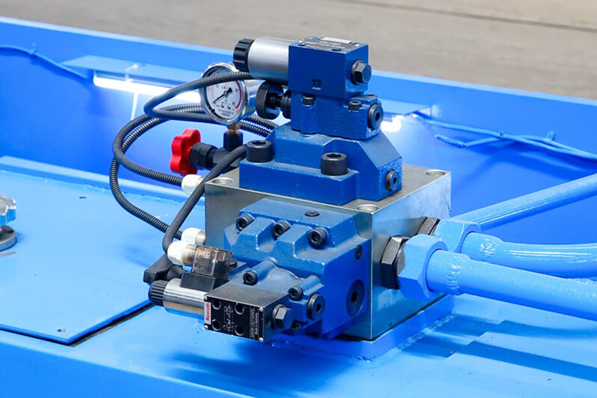
- Examine Its “Power Heart” and “Control Brain”: The Brand and Quality of Core Hydraulic Components
This is non-negotiable. The reliability and performance potential of the machine are directly determined by the quality of its core hydraulic components (pumps, valve assemblies, and main cylinders). Always request a detailed configuration list from the supplier to verify the specific brands and model series of these critical parts. Top-tier global brands such as Bosch Rexroth and Parker are synonymous with proven reliability in the world’s toughest industrial environments. They typically deliver longer mean time between failures, lower internal leakage rates, and more precise control response. Choosing equipment equipped with such premium components is, in essence, investing in the long-term stability and productivity of your operation—an expensive but invaluable form of insurance. - Evaluate Its “Intelligent Core”: The Advancement and Usability of the Control System
In today’s market, CNC/NC control systems are standard in hydraulic shearing machines, yet their “intelligence” and “user experience” vary dramatically.
A truly outstanding control system should possess several key qualities: it must be intuitive and user-friendly, with a graphical programming interface that greatly shortens operator training time and reduces defects or accidents caused by human error; it should be highly capable, offering functions such as automatic calculation of cutting angles and blade gaps, self-diagnosis and alarm systems, and material database management—all of which significantly boost production efficiency; and finally, it should be open and connected, with interfaces capable of integrating with higher-level MES/ERP systems—an essential gateway for participating in the future of smart manufacturing.
- Inspect Its “Steel Backbone”: Frame Rigidity and Structural Design
The frame is the bedrock that withstands hundreds of tons of shearing force; its rigidity and stability determine whether the machine can maintain precision over years of operation. A first-rate shearing machine will feature a frame that is massive and robust. Check whether it uses an integrated welded structure, followed by rigorous stress-relief treatment such as annealing or vibration aging. Though these processes may seem old-fashioned or heavy-handed, they effectively prevent permanent deformation under sustained loads, ensuring long-term stability of blade clearance—and, by extension, your ability to consistently produce high-precision components over the next decade. - Verify Its “Safety Shield”: Safety Grade and Design Integrity
Safety is non-negotiable in any production environment. The first step is to confirm that the machine complies with your region’s mandatory safety standards, such as CE certification in the EU. Beyond compliance, assess the reliability and ergonomics of its safety mechanisms on-site. Is the light curtain (photoelectric guard) fast and comprehensive in its response? Are the rear physical barriers sturdy and equipped with safety interlocks? Are emergency stop buttons strategically positioned for instant access from any operator stance? When it comes to safety, “good enough” is never truly good enough.
To review the full specifications and safety certifications of our equipment, we invite you to download our brochures.
- Assess Its “Lifeline”: After-Sales Service and Technical Support
Purchasing a machine means acquiring an integrated package of hardware, software, and service. A supplier’s after-sales capability is your true operational “lifeline,” directly determining equipment downtime. Investigate the following: Service network coverage—does the supplier maintain certified resident engineers in your area? Response time commitments—how long from your service call until a technician is on-site: four hours or forty-eight? Spare parts inventory—are frequently needed consumables stocked locally? Training system quality—do they offer only basic operational instruction, or comprehensive maintenance and optimization training as well? A competent, responsive service team is the unseen safeguard that protects and enhances the long-term value of your equipment investment.
Ⅶ. Frequently Asked Questions
1. What is a hydraulic system in a shearing machine?
A hydraulic system in a shearing machine uses fluid mechanics to generate and control high forces required for cutting metal sheets. It consists of components like hydraulic pumps, cylinders, control valves, and hydraulic fluid, which work together to convert mechanical energy into hydraulic energy and back into mechanical energy for precise and efficient cutting.
2. Can hydraulic shearing machines be used for materials other than metal?
Yes, hydraulic shearing machines can be used for materials other than metal, such as plastics and composites, depending on the machine's design and specifications. However, the cutting parameters may need to be adjusted to accommodate the different properties of these materials. It's essential to consult the manufacturer's guidelines to ensure the machine is suitable for cutting non-metallic materials.

3. What safety measures should be taken when operating a hydraulic shearing machine?
- Personal Protective Equipment (PPE): Operators should wear appropriate PPE, including gloves, safety goggles, and protective clothing.
- Machine Guarding: Ensure all safety guards and barriers are in place and functioning correctly to prevent accidental contact with moving parts.
- Training: Only trained and certified personnel should operate hydraulic shearing machines. Comprehensive training includes understanding machine controls, safety protocols, and emergency procedures.
- Lockout/Tagout Procedures: Implement lockout/tagout procedures during maintenance to prevent accidental machine start-up.
- Emergency Stops: Familiarize operators with the location and operation of emergency stop buttons.
- Regular Inspections: Conduct routine inspections to identify and rectify potential safety hazards, such as hydraulic leaks or worn components.
For any further questions or to discuss your specific application needs with an expert, please feel free to contact us.


