I. What Is A Press Brake
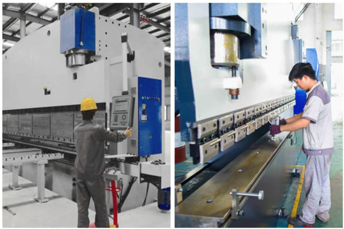
Press brake is a metal bending machine used in the metal fabrication industry for bending sheet metal to various shapes and angles. How does a press brake work?
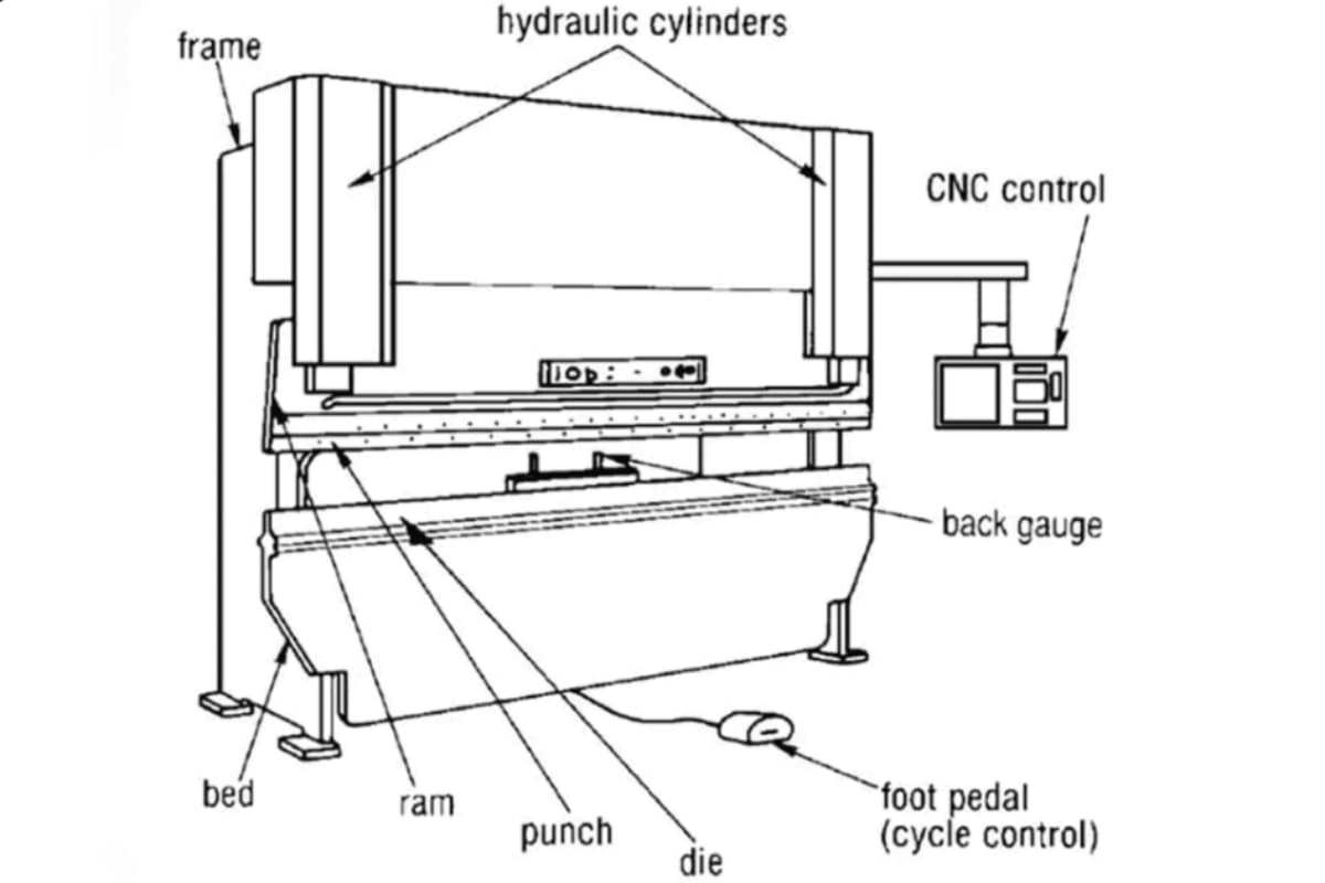
The precision sheet metal bending process is accomplished by applying force on the point of the bend. The metal sheet is placed between the punch and the die on the press brake machine. The punch is the upper component, and the die is the lower component.
The press brake machine exerts force on the metal sheet through the punch, causing it to bend or deform according to the shape of the die. As the punch forces the plate metal into the die, the material bends.
It drives punches and dies through different driven sources to bend repeatable sheet metal and form profiles. Materials of different thicknesses and bending lengths require different bending forces. Simply put, press brake forming is a process used to bend and shape piece of sheet metal. For specialized bending shapes such as U-shaped profiles, you can learn more in Press Brake U-Bending: Methods and Uses.
Bending force, measured in tonnage, is the force exerted by the press brake. Press brake tonnage determines the press brake’s load limit. If a press brake has a higher tonnage, it can bend thicker and longer sheet metal. Different types of press brakes produce tonnage in different ways.
The hydraulic press brake machine is suitable for bending with large tonnage, while driven sources are generally divided into mechanical, hydraulic, electric, and pneumatic types. For those interested in understanding cutting processes that often precede bending, the Guide to Hydraulic Shearing Machines provides a comprehensive overview of how sheet metal is prepared before forming.
The name of the press brake is determined by the driving method. For example, the pneumatic bending machine drives the ram through air pressure, while the servo-electric press brake drives the ram using a servo motor. The servo-electric press brake offers very high precision and speed. Ensuring this precision also requires attention to machine alignment and parallelism — for a deeper understanding of this crucial aspect, see Understanding Press Brake Parallelism.
II. How Does A Press Brake Work
Bending a tough metal sheet into a precise angle is far from a simple brute-force operation—it’s a scientifically controlled process that manipulates the material’s physical properties on a microscopic scale. Understanding this underlying principle is the key step in transforming from an operator to a master of the craft. It’s not just about knowing how to do it, but why it must be done that way.
2.1 The Physics of Bending: From Elastic Deformation to Plastic Forming
When the upper punch of a press brake contacts and begins to push down on the workpiece, the material’s internal structure is engaged in a dynamic “tug of war” of stress. This behavior can be precisely represented by the classical stress–strain curve.
- How Metal ‘Yields’ and Takes Permanent Shape
- Elastic Stage: At the initial stage of loading, the metal behaves like a finely tuned spring—the deformation is temporary and reversible. Once the force is removed, it returns to its original shape. This phase has no lasting effect on forming, yet it is a necessary transition.
- Yield Point: This is the critical “trigger moment” in the entire bending process. When the applied stress exceeds the yield strength of the material, atomic bonds within the metal begin to slip, break, and reorganize, entering the irreversible stage of plastic deformation.
- Plastic Stage: Beyond the yield point, even after the force is released, the material no longer fully returns to its original shape—permanent deformation remains. Sheet metal forming takes advantage of this property, applying pressure well above the yield point so the metal “gives in” and retains the designed shape.
- Neutral Axis and Bend Compensation: Why Dimensions Change After Bending
A common misconception is that bending merely alters shape. In reality, it changes the unrolled length of the material—an essential foundation in precise sheet metal design. - Springback Effect: The Challenge of Material ‘Memory’ and Compensation Strategies
Once the punch returns and pressure is released, the bent metal does not perfectly retain the angle formed by the die. Residual elastic stresses cause it to “spring back,” making the final angle slightly larger than intended. This phenomenon is known as springback.- Influencing Factors: The higher the yield strength and the lower the elastic modulus (as with high-strength steel, stainless steel, or aluminum alloys), the more pronounced the springback.
- Compensation Strategies: The simplest way to compensate is overbending—for example, to achieve a 90° angle, the machine may be set to bend to 88°, relying on springback to reach the target precisely. Modern CNC systems incorporate material databases or advanced real-time laser angle measurement to automatically calculate and compensate for springback, achieving accurate bends in a single pass.

2.2 The Complete Bending Process: A Step-by-Step Visual Breakdown
A typical CNC bending operation can be viewed as a precisely choreographed ballet, broken down into five seamlessly connected stages:
- Step 1: Positioning: The operator places the sheet metal flat on the lower die and pushes it backward until its edge precisely contacts the back gauge fingers. The back gauge position, controlled by the CNC system with micron-level precision, directly defines the flange width.
- Step 2: Pressing: The ram drives the upper punch downward from the top dead center in a high-speed “approach” motion, automatically switching to the programmed work speed just millimeters above the surface to ensure safety and accuracy.
- Step 3: Forming: The punch continues downward at a stable work speed, pressing the sheet into the V-shaped groove of the lower die. When the pressure surpasses the material’s yield strength, plastic deformation begins. The depth and force are monitored in real time by the CNC system.
- Step 4: Holding/Bottoming: The ram reaches the bottom dead center position calculated by the CNC system and may hold briefly, depending on the process setting (such as bottoming), to ensure accurate angle formation and minimize springback.
- Step 5: Retracting: The ram quickly rises to a programmed safety height or back to the top dead center, completing one bending cycle. The operator can then safely remove or reposition the workpiece for the next bend.
2.3 The Three Main Bending Methods: Choosing the Right One Determines Efficiency and Precision
Selecting the appropriate bending method is not a matter of personal preference—it’s a strategic decision that affects tonnage requirements, precision, efficiency, and die longevity. The key distinction among the methods lies in the interaction between the upper die, the workpiece, and the lower die.
For a broader understanding of how bending and cutting interact across manufacturing processes, you can refer to Press Brake and Shearing Machine Overview.
| Feature | Air Bending | Bottoming | Coining |
|---|---|---|---|
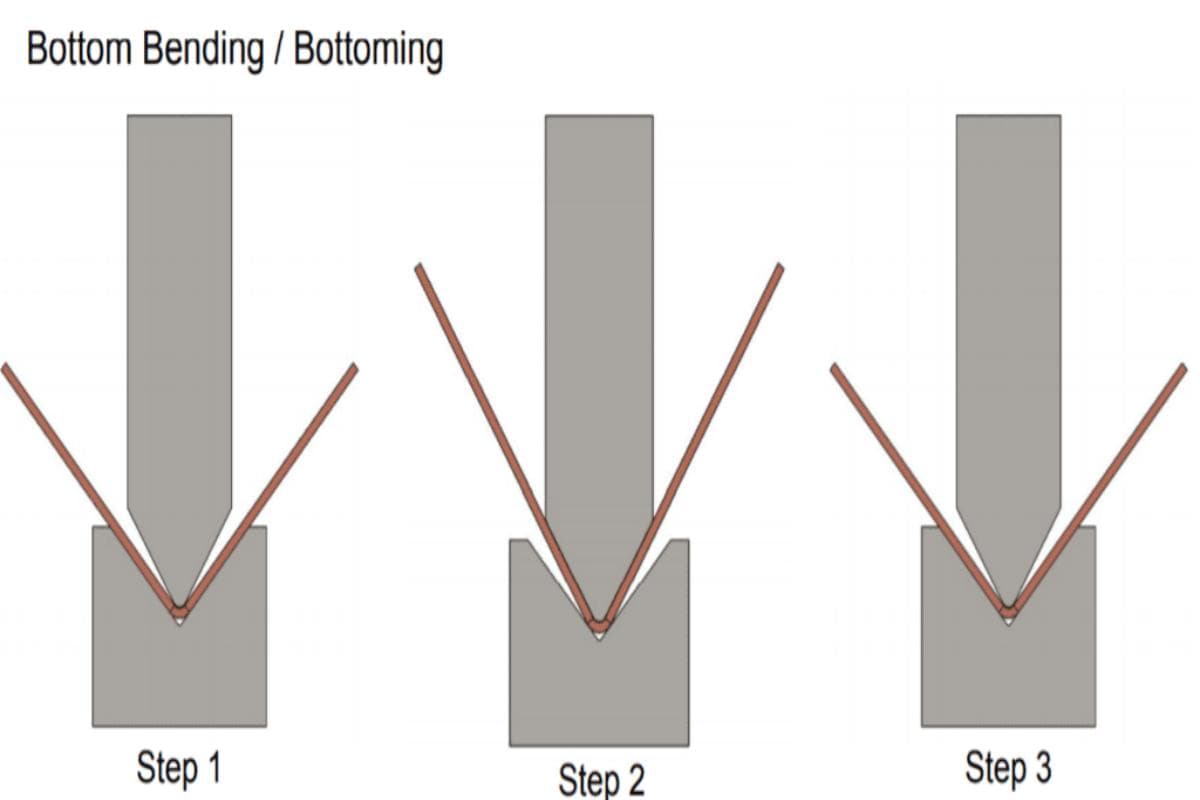
| Operating Principle | The punch presses the workpiece into the V-shaped die without touching the die bottom, creating a three-point contact. The bend angle is determined by how deeply the punch penetrates the V opening. | The punch compresses the workpiece so its inner surface conforms closely to the die’s angled sides; the bend angle is defined by the tool’s own geometry. | Using extremely high pressure, the punch forces the material fully into the die cavity, thinning the sheet and reproducing the die’s shape precisely—similar to minting a coin. |
| Tonnage Requirement | Lowest—serves as the baseline for comparison. | Moderate—typically 2–4 times higher than air bending. | Very high—often 5–10 times (or more) greater than air bending, placing extreme stress on both the machine and tooling. |
| Accuracy | Medium to high. Most affected by spring-back, but modern CNC systems compensate effectively, achieving precision sufficient for most applications. | High. The compression minimizes spring-back significantly, ensuring good repeatability. | Highest. Virtually eliminates spring-back and delivers exceptional angle consistency. |
| Flexibility | Excellent. A single die set (e.g., 88° punch and die) can produce a wide range of angles—from acute to obtuse—simply by adjusting the depth of penetration. | Limited. The die angle must closely match the desired bend (e.g., a 90° bend requires a 90° die). | Minimal. Each die set produces only one fixed angle, offering no flexibility at all. |
Ⅲ. Type of Press Brakes and Their Working Principles
Press brake uses force to bend the metal plate, which is a useful equipment in the metal industry. At present, modern press brakes often adopt computer numerical control systems in metal forming and fabricating. Using a CNC press brake can handle all kinds of complex and mass workpiece metal forming tasks.
3.1 Types
Here is a detailed comparison of different types of press brakes (hydraulic, mechanical, CNC, and pneumatic) along with their respective advantages and disadvantages:
| Type | Advantages | Disadvantages | Typical Applications |
| Mechanical Press Brake | Fast processing speed, simple structure | Difficult to adjust pressure; low force for thick materials | Bending small parts where precision is less critical |
| Hydraulic Press Brake | High precision and force; versatile | Complex maintenance; potential hydraulic leaks | Heavy machinery, automotive, aerospace |
| Pneumatic Press Brake | High-speed operation; low maintenance | Limited force; not suitable for heavy-duty applications | Lightweight materials, small-scale parts |
| Servo Electric Press Brake | High precision; energy efficiency; low noise | Potential electrical hazards; requires precise maintenance | High-precision tasks; energy-sensitive environments |

(1) Mechanical Press Brake
The mechanical press brake drives the flywheel through the motor. The operator operates the clutch to control the flywheel, and the crank drives the movement of other parts. The operation of a press brake is relatively simple, and it can handle large tonnage bending but lack the precision and flexibility of hydraulic or servo-electric systems.
Key Components
- Flywheel, Crank Mechanism, and Clutch:
A motor drives the flywheel, which stores energy and releases it through the crank mechanism and clutch to move the ram. - Ram:
Applies force to the metal sheet, shaping it with the punch and die.
Advantages
Mechanical press brakes are fast and ideal for mass production, making them cost-effective for large volumes.
Disadvantages
However, they offer less precision and flexibility compared to hydraulic and servo-electric models.
(2) Hydraulic Press Brake
The machine tool drives the ram movement with two synchronized hydraulic cylinders on the C-frames, allowing for greater control over the bending process. The cylinder is connected to the ram through the piston rod, and the ram is powered by hydraulic cylinders.
The movement of the hydraulic cylinder drives the ram up and down. The movement modes of the hydraulic press brake are divided into up-moving and down-moving. The back gauges accurately position the workpiece through the movement of different axes.
Hydraulic press brakes have become a staple in the metalworking industry due to their high speed and high precision. However, the tonnage of bending is limited, which is a disadvantage.
Key Components
- Hydraulic Cylinders: Filled with oil to generate the force to move the ram.
- Control System: Regulates hydraulic pressure, ensuring consistent and accurate bending.
- Ram: Delivers force to the metal sheet, shaping it with the punch and die.
Advantages
They offer high precision, handle thicker materials, and are versatile for various applications.
Disadvantages
They are slower than mechanical models and need regular hydraulic system maintenance.
(3) Servo-Electric (CNC) Press Brake
The CNC press brake is a hydraulic press brake equipped with a CNC control system that controls the movement of each part with modular programming functions and high precision and handles different tonnages and bending lengths.
Additionally, the CNC press brakes are equipped with an automatic feeding system that accurately controls the position of the workpiece through the movement of the ram and back gauge. Synchronous movement of the motor drive axes of the back gauge and the ball screws. The back gauge can accurately measure the length of the flange being formed.
Key Components
- Servo Motor and Ball Screw: Servo motors control the ram's movement through a ball screw, providing precise and programmable control.
- Ram: Applies force to the metal sheet, shaping it with the punch and die.
- CNC Control System: Provides programmable control for high precision.
Advantages
They offer high accuracy, are energy-efficient, and require minimal maintenance. The operating sound of the servo press brake is very low, and it will not produce noise during operation.
Disadvantages
However, they have a higher initial cost and limited force compared to hydraulic press brakes.
(4) Pneumatic Press Brake
Pneumatic press brakes allow compressed air to operate the ram. They are generally lighter and more compact than hydraulic models, with faster setup and bending operation times. These press brakes are ideal for light to medium-duty tasks such as HVAC work.
Key Components
- Air Pressure System: Compressed air operates the ram.
- Ram: Delivers force to the metal sheet, shaping it with the punch and die.
- Control System: Regulates air pressure and movement.
Advantages
They are fast, lightweight, and cost-effective for light to medium-duty tasks.
Disadvantages
However, they have limited force and are not suitable for heavy-duty applications.
3.2 Common Bending Methods
Adjust the bending angle by adjusting the ram movement through the control system. There are basically three bending methods: air bending, bottom bending, and embossing bending. The choice of bending method has a great relationship with the thickness of the bending plate.
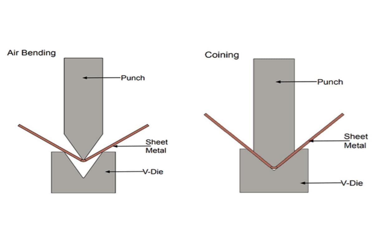
Air bending is the most commonly used bending method, where the workpiece is not in full contact with the bottom die. It can be carried out with relatively small tonnage. Bottom bending and coining methods can also be used as needed.
During bending, the hydraulic cylinders drive the movement of the ram, which in turn drives the upper die to apply pressure on the lower die on the workbench. The sheet metal in the middle is formed into a specific angle through the extrusion of the die, and after repeated bending, the final profile is obtained.
The angle and shape of the metal plate are determined by the shape of the punches and dies, as well as the movement of the ram. The CNC press brake offers flexible numerical control and programming functions, making it operator-friendly.
Ⅳ. How to Set Up a Press Brake?
First of all, it is critical to understand the drawing of the bending workpiece. Determine the material, length, and thickness of the workpiece, as well as the bending angle, bending radius, flange dimension, and tolerance of the workpiece. Secondly, choose the appropriate bending method and die.
Select the appropriate bending method based on the relationship between the bending radius and metal thickness, such as air bending, bottom bending, or coining. Choose a punch and die set that match the material of the bending workpiece. Thirdly, determine the tonnage according to the tonnage table.
Consult the corresponding tonnage estimation provided by the manufacturer. If it is air bending, you can refer to the tonnage chart to determine the tonnage. The tonnage of bottom bending is four to six times that of air bending, and the tonnage of coining is eight to ten times that of air bending tonnage.

Press brake tooling plays a crucial role in achieving bending sheet and plate metals. Install and adjust the press brake tooling, including checking the thickness and proportion of the upper and lower dies, adjusting the stroke of the ram, adjusting the upper limit point of the toolings to reserve the stay position of the ram, and setting an appropriate gap between the upper and lower dies.
Perform the program procedure of the press brake, familiarizing yourself with the functions of the CNC controller, programming offline, and using scrap plates for a bending test. To see this process in action, you can view a detailed video guide on How to Program Press Brake Bending with the Delem DA 53TX Controller. If there is a problem with the bent workpiece, check and correct the program, and operate the press brake accordingly. These steps can save costs and improve efficiency.
Ⅴ. Cases and Application
5.1 Automotive Industry
Press brakes are crucial in the automotive industry for manufacturing car components like brackets, chassis, body panels, and exhaust systems. Their precision ensures parts meet strict specifications, enhancing vehicle quality and safety.
5.2 Aerospace Industry
In the aerospace industry, press brakes produce critical components like aircraft frames, wing parts, and engine covers. They ensure precision and reliability by bending aluminum and titanium alloys to meet aerospace requirements.
5.3 Home Appliance Industry
Press brakes are used in the home appliance industry to produce refrigerator panels, washing machine housings, and air conditioner components. Their precision and flexibility enable accurate bending of metal sheets to meet design specifications.
5.4 Construction Industry
Press brakes are used in the construction industry to manufacture structural components and metal elements like I-beams and metal decking for building projects.
5.5 Furniture Manufacturing
In furniture manufacturing, using a press brake to create metal frames, brackets, and decorative parts, bending metal sheets into shapes and angles that enhance furniture design and functionality.
5.6 Medical Equipment
Press brakes in the medical equipment manufacturing industry produce precise metal components, and bending sheets to meet medical device specifications, enhancing efficiency and quality. For example, press brakes are used to create components for surgical instruments, diagnostic equipment, and hospital furniture, where precision is paramount to meet safety and performance standards.
5.7 Electronics and Electrical Equipment
Press brakes are used in the electronics industry to produce precise metal housings and components, such as bent metal sheets for housings and brackets that ensure device functionality and safety.
5.8 Defense Industry
In the defense industry, press brakes are used to manufacture high-strength metal plates and alloy components like ammunition storage containers, armored vehicles, and armor plates, enhancing the durability and safety of military equipment.
Ⅵ. Common Faults of Press Brakes and Solutions
| Fault Phenomenon | Possible Causes | Solutions |
| No pressure or insufficient pressure in the hydraulic system | 1. Incorrect forward or reverse rotation of motor and pump 2. Blocked spool of overflow valve 3. Blocked spool of solenoid valve 4. Internal leakage of pressure control valve | 1. Check the rotation direction of motor and pump 2. Clean the spool of overflow valve 3. Clean the spool of solenoid valve 4. Check the pressure control valve |
| Slow or jerky descent of ram | 1. Worn or damaged cylinder 2. Worn or non-vertical guide rails 3. Low oil level in tank 4. Fast forward speed, insufficient oil supply 5. Stuck and not fully open filling valve | 1. Check the cylinder 2. Check the guide rails 3. Check the oil level 4. Adjust the fast forward speed 5. Clean the filling valve |
| Oil leakage in the hydraulic system | 1. Loose connecting screws and pipe fittings 2. Damaged seals | 1. Tighten screws and fittings 2. Replace seals |
| Unbalanced bending on both sides | 1. Uneven wear of dies 2. Non-parallel ram | 1. Adjust the hexagonal tube to correct the angle difference 2. Adjust the parallelism with eccentric sleeves |
| Loud noise | Loose connections, worn bearings, damaged parts | Adjust the ram, replace dies if necessary |
| Electrical faults | Loose wiring, sensor failure, damaged circuits | Check wiring, replace sensors or circuits |
| Overheating | Blocked radiator, cooling system failure | Clean the radiator, repair the cooling system |
| Ram cannot descend slowly, weak bending force | 1. Failure of 4/2-way valve 2. Stuck filling valve | 1. Check the 4/2-way valve 2. Clean the filling valve |
| Slow return speed of ram, high return pressure | Filling valve not open | Check the filling valve |
Ⅶ. Practical Operations Manual: Achieving Your First Perfect Bend from Scratch
Theoretical knowledge serves as the map to mastery, but only hands-on practice gets you to the destination. This chapter moves beyond theory into a step-by-step tactical guide — precise down to every movement. We’ll walk you through the process, beginning with cultivating an unshakable safety culture, then breaking down and executing a flawless 90‑degree bend, and finally unveiling a game‑changing secret weapon that could redefine your concept of efficiency: the digital twin.
7.1 Before Startup: Essential Safety Culture and Preparation Checklist
In manufacturing, safety is not a list of rules to memorize — it’s a culture ingrained into every action. Building an unbreakable safety boundary before pressing that green start button is where every excellent process begins. Overlooking even the smallest detail can lead to irreversible consequences.
- Personal Protective Equipment (PPE): The Operator’s Everyday Armor
- Safety Shoes: These must be steel-toed. A falling sheet or die can easily cause severe injury from impact.
- Safety Goggles: During bending, sudden stress release can send tiny metal fragments flying at high speed. Eye protection is non‑negotiable.
- Cut‑Resistant Gloves: Sheet metal edges, especially post‑cutting, are razor‑sharp. These gloves are essential to prevent lacerations when handling or positioning parts.
- Dress Code: Avoid scarves, ties, or any hanging accessories; long hair must be secured under a cap. Loose clothing poses a deadly risk of being caught in moving machinery.
- Equipment Inspection: Five Minutes That Prevent Ninety Percent of Accidents
- Safety Device Check: Upon startup, first test the light curtain or laser safety system for responsiveness. Place a scrap piece in its path — the ram should stop immediately. Verify all emergency stops are fully functional and readily accessible.
- Tooling Condition: Visually inspect the punch and V‑die for cracks, chipping, or abnormal wear. Under tens of tons of pressure, a tiny defect can lead to catastrophic die failure.
- Hydraulic System Check (if applicable): Confirm that oil levels are within normal range, and scan both floor and line joints for any trace of leakage.
- Electrical Connections: Ensure all cables are firmly attached, with no exposed wires or damaged insulation, to guarantee electrical safety and reliability.
- Workspace Organization: The Foundation of Safety and Efficiency
- Clear the Operating Area: Make sure the space around the press brake — especially near the foot switch — is free from tools, clutter, oil, or debris. A clean floor eliminates slip and trip hazards.
- Material Zoning: Keep raw sheets and finished parts separate and neatly stacked. Prevent confusion, and always maintain enough space for operators to move safely and comfortably.

7.2 The Five‑Step Core Bending Method (Example: 90‑Degree Air Bend)
Once preparation is complete, we’ll deconstruct the entire process using the most fundamental and classic form — a 90‑degree air bend.
- Step 1: Die Selection — Adhering to the “8× Rule”
This isn’t just a loose recommendation but a golden rule distilled from decades of industry experience: The V‑opening width of the lower die should be roughly eight times the thickness of the sheet.- The Science Behind It: This ratio achieves the ideal balance between bending force, inner radius, and springback. For standard carbon steel, it produces an inside bend radius approximately equal to the material thickness — structurally optimal and process‑stable.
- What Happens If You Ignore It:
- V‑Opening Too Narrow (<6×): The required tonnage increases exponentially, risking machine overload or permanent tooling damage. The bend radius also becomes too tight, overstretching the outer fibers and causing cracks.
- V‑Opening Too Wide (>12×): The bend radius grows excessively large, making precision control difficult and increasing springback. Short flanges may even drop into the die cavity and fail to form.
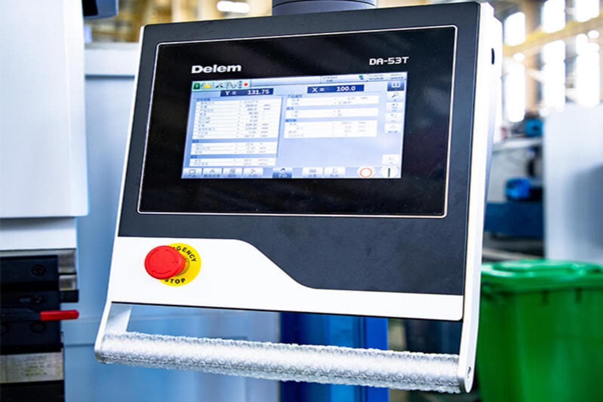
- Step 2: Parameter Setup — Communicating with the Machine’s Brain
On a modern CNC press brake interface, you input the key commands that allow the system to interpret your intent:- Material Type: Select precisely, such as “mild steel,” “304 stainless,” or “5052 aluminum.” The built‑in database will automatically optimize calculations based on tensile strength and modulus of elasticity.
- Sheet Thickness: Measure accurately with a vernier caliper and input the exact value to two decimal places. Even 0.1 mm can alter the bend angle.
- Bend Length: Enter the actual width of the part for this bend.
- Target Angle: 90 degrees for this example.
After data entry, the CNC instantly calculates the theoretical ram depth (Y‑axis stroke), required tonnage, and initial springback compensation.
- Step 3: Back Gauge Positioning — Defining the Dimensional Reference
The back gauge is the sole reference ensuring flange width consistency.
Pro Tip: When positioning the workpiece, make sure its edge makes full, seamless contact with at least two back‑gauge fingers. Gently push the sheet backward until you feel solid contact. Single‑point or loose contact is the prime cause of size variation. Multi‑axis back gauges (e.g., Z1/Z2) allow the fingers to move laterally to fit different widths or bypass irregular contours. - Step 4: Test Bend and Compensation — Your First Encounter with SpringbackNever perform the first production bend on an actual part.
This marks the difference between a beginner and a professional.- Material Sample: Use a scrap piece of the exact same material and thickness as the production part.
- Perform: Complete one full bending cycle.
- Measure: Use a high‑precision digital protractor to check the actual bend angle.
- Analyze: If your target is 90°, and the reading shows 91.2°, that indicates 1.2° of springback.
- Compensate: On the CNC “angle compensation” screen, input the offset (+1.2° or simply 91.2°, as prompted). The system will automatically adjust the Y‑axis stroke to “overbend” slightly, bringing the final result precisely to 90° after springback. Repeat until the angle stays consistent within tolerance.
- Step 5: Mass Production — First Piece Inspection and Process Control
Once parameters have been fully calibrated, proceed to manufacture the first formal workpiece. Upon completion, conduct a rigorous
First Article Inspection (FAI)—checking every dimension and angle against the engineering drawing. Only when the first piece meets 100% of the specifications can batch production begin. Continue with periodic sampling during production to monitor and prevent any deviations.
7.3 Three Common Beginner Mistakes and How to Avoid Them
Mistake 1: Ignoring springback—naively assuming that a programmed 90° bend will result in an actual 90° bend.
- Consequence: Every part in the batch ends up with an excessive bend angle, making assembly difficult or leading to complete rejection—wasting both materials and labor.
- How to avoid it: Internalize the cycle of “test bend–measure–compensate” until it becomes second nature. Understand that springback is an inherent physical property of the material, and learn to harness it through the CNC’s intelligent compensation features rather than ignoring it.
- Mistake 2: Choosing the V-die by intuition—grabbing whatever tooling feels right.
- Consequence: A V-slot that’s too narrow causes surface cracking or triggers frequent overload alarms; one that’s too wide results in bends with an overly large radius, deviating significantly from design specifications.
- How to avoid it: Treat the “8× rule” as your guiding principle, and always refer to the tonnage charts provided by the machine manufacturer. When uncertain, err on the side of a slightly wider V-slot for safety—never risk using one that’s too narrow.

- Mistake 3: Neglecting accurate backgauge positioning—failing to ensure full contact between the workpiece and the stops.
- Consequence: Bend dimensions fluctuate from part to part, resulting in poor consistency and parts outside drawing tolerances.
- How to avoid it: Make double-checking each positioning step a habit. Use tactile feedback to ensure the workpiece is firmly in contact with all stops. For complex parts, learn to use the backgauge’s R-axis (vertical movement) or multipoint positioning functions to keep the reference plane flawlessly accurate.
7.4 [Unique Insight #3] Digital Twin: Leveraging Offline Programming Software for Efficiency Gains
In the traditional approach, programming, setup, and test bending consume valuable machine uptime—periods when the press brake generates zero productivity.
Offline programming software, as a powerful embodiment of Digital Twin technology in sheet metal fabrication, is revolutionizing this inefficient paradigm.
What is a Digital Twin?
Imagine that your computer contains a perfect 1:1 virtual clone of the physical press brake on your shop floor—replicating its geometry, motion axes, control logic, and complete tooling library. That virtual replica is your Digital Twin.
How does it trigger an efficiency revolution?
(1) Shift the machine’s “thinking time” to the desktop:
Engineers can directly import 3D models of parts into their computer. The software automatically analyzes them, recommends the optimal tool combination, and intelligently plans the most efficient bending sequence. This process compresses hours of programming into mere minutes while the physical machine continues uninterrupted production. Once finalized, the program is sent to the press brake with a single click—ready to run immediately.
(2) Simulate success virtually to avoid costly real-world errors:
The most impressive feature of offline programming is its full 3D dynamic simulation capability, which allows engineers to preview the entire bending sequence just like a movie.
- See the invisible:
The software visually highlights potential collision points in bright red—such as a formed flange striking the punch, the table, or the machine frame. In the past, these risks were discovered only through expensive trial-and-error and damaged workpieces. Now, engineers can quickly adjust the bend order or swap tooling (for example, using a gooseneck punch to avoid interference) until achieving a fully safe and efficient process.
This approach—“perfecting the process in the virtual world and executing flawlessly in the real one”—maximizes the press brake’s Overall Equipment Effectiveness (OEE). It represents more than mere software; it embodies a smarter production philosophy and defines the competitive edge separating modern sheet metal shops from traditional workshops.
Ⅷ. Mastery and Optimization: From Skilled Operator to Process Artisan
Mastering the basics earns you entry into the arena; becoming a champion requires mastering advanced techniques, developing expert diagnostic skills, and learning how to care for your machine with precision. This chapter represents your leap from competence to mastery—exploring the wisdom that distinguishes simply “operating” from truly “mastering.”
8.1 Advanced Techniques: Unlocking the Ability to Form Complex Shapes
Standard bending deals with straight lines, but real-world products abound with curves and intricate geometries. Unlocking the ability to process these complex forms is the first gateway on the path to true craftsmanship.
- Large Radii and Multi-segment Bending (Bumping/Step Bending)
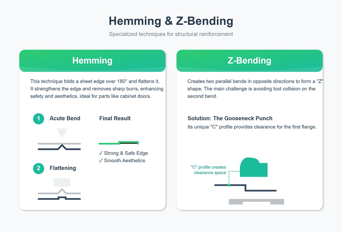
Standard V-dies produce fixed-radius bends, but achieving a smooth, large arc requires the wisdom of step bending—the art of “dividing the whole to master the details.” Here, a broad curve is broken into a series of extremely small (e.g., 0.5°–1°) closely spaced bends. The CNC system precisely controls micro-step movements of the backgauge while applying shallow ram strokes, gradually forming what appears to be a seamless arc at the macro level. It demands exceptional accuracy in both backgauge stepping and ram repositioning, serving as a true test of machine precision and programming skill. - Hemming and Z-Bending
These two processes—requiring specialized tooling and meticulous planning—are typical examples of complex bends used for structural reinforcement and intricate assemblies.- Hemming: This technique folds the sheet edge over 180° and flattens it, usually in two stages. First, a sharp-angle tool (e.g., 30°) forms a tight bend; second, a flattening die compresses it into a double-layer edge. The result greatly strengthens the sheet’s edge while eliminating sharp burrs, making it ideal for applications such as cabinet doors—where safety and smooth aesthetics are essential.
- Z-Bending: This involves creating two parallel bends in opposite directions to form a “Z” shape. The challenge lies in preventing collisions between the formed flange and the machine or tooling during the second bend. Solutions highlight the craft’s adaptability:
Using a Gooseneck Punch: The punch’s distinctive “C” profile provides clearance space for the previously formed flange—offering the most common and efficient solution.
- Special Z-type Die (Z-Die): A highly efficient, purpose-built tool that can form both bends in a single downward stroke. It dramatically improves productivity but requires additional investment, making it ideal for mass production environments.
- Deflection Compensation (Crowning) – The high-tech cure for the “banana effect”.
This is a critical, yet often overlooked phenomenon when working with long workpieces. As the press brake bends a long piece—say, three meters or more—the immense tonnage causes the ram (upper beam) and the bed (lower beam) to slightly flex downward at the center, imperceptible to the naked eye. It’s similar to how a bridge sags under load. This flexing is known as deflection.
Consequence: The deformation causes the center of the workpiece to receive less pressure than the ends, producing the so-called “banana effect”—adequate bending angles at both ends but overly large angles in the middle.
Solution: The Crowning System. Instead of passively accepting deformation, it counteracts it. By applying a precisely calibrated upward force beneath the bed, it creates a controlled convex curve that offsets the deflection caused by the downward tonnage. As a result, the gap between upper and lower dies remains perfectly parallel along the entire bending length.
Whether a press brake is equipped with and effectively utilizes a deflection compensation system serves as a defining measure of both the machine’s and the operator’s capability in achieving high-precision bending of long workpieces.
8.2 Quality Control and Troubleshooting: Think Like an Expert
The true value of a skilled process engineer lies not only in producing flawless results, but also in the ability to quickly diagnose and resolve problems. Here’s a model of expert-level analytical thinking:
| Common Issue | Possible Cause (from simple to complex) | Expert Troubleshooting Guide |
|---|---|---|
| Inconsistent Angles | 1. Uneven material thickness: tolerance variations across a single sheet. 2. Tool wear: the lower die’s V-groove shoulders or the upper die tip have worn over time. 3. Off-center loading: bending performed away from machine center causes uneven deflection. 4. Hydraulic oil temperature variation (in hydraulic presses): rising temperature lowers viscosity, affecting system stability. 5. Insufficient crowning: incorrect compensation setting or inactive system. | 1. Use a caliper to measure thickness at multiple points on the sheet to confirm tolerance. 2. Inspect and measure critical die surfaces; if wear exceeds 0.1mm, replace or refinish. 3. Always align the bending center with the machine’s center. 4. Maintain stable hydraulic system temperature; check the cooling unit. 5. Recalibrate or adjust the crowning value. |
| Surface Scratches | 1. Dirty tooling: metal chips or dust on die surfaces. 2. Direct contact: friction occurs between workpiece surface and lower die shoulders during bending. 3. Faulty PVC protective film: film tears during bending. | 1. Before each setup, wipe die surfaces clean with a lint-free cloth. 2. Use scratch-free bending protection film—a durable polyurethane sheet placed over the lower die so the workpiece contacts only the film. 3. Check film condition or switch to thicker protection film. |
| Cracks at Bend Root | 1. Bend radius too small: violates material’s minimum bend radius requirement. 2. Incorrect bending direction: bend line runs parallel to material grain direction. 3. Material defect: poor ductility or internal flaws. | 1. Strictly follow the “8× rule” or use a larger V-die to increase natural bend radius. 2. Most critical yet often overlooked: during layout planning, ensure bend lines are perpendicular to grain direction. Like folding paper, folds along fibers are easy—perpendicular folds tend to crack. 3. If design allows, switch to material grades with better ductility. |
8.3 Maintenance and Care: Best Practices for Extending Equipment Life and Accuracy
Your equipment is a partner, not just a tool. Systematic maintenance directly safeguards precision, efficiency, and the return on your investment.
- Daily
- Cleaning: Remove debris and oil residue from the machine, worktable, tooling, and floor to keep the workspace tidy.
- Lubrication: Follow the manufacturer’s manual to oil key moving components such as guide rails and lead screws.
- Safety Check: Before starting up, test safety systems (light curtain, emergency stops) for proper operation, and visually inspect for leaks of oil or air.
- Weekly
- Hydraulic System: Inspect oil level and cleanliness. If the oil appears milky (water contamination) or overly dark (oxidation), schedule replacement immediately.
- Backgauge Calibration: Use gauge blocks or specialized calibration tools to check positioning accuracy and repeatability, making fine adjustments as needed.
- Fastener Inspection: Check bolts on die clamping devices and backgauge assemblies for looseness.
- Annually
- Replace Hydraulic Oil and Filters: Typically every 4,000–6,000 operating hours or once a year. This is vital for maintaining the health of the hydraulic system.
- Comprehensive Precision Calibration: Have professional service engineers check and calibrate ram parallelism, full-axis backgauge accuracy, and the crowning system.
- Electrical System Inspection: Clean the control cabinet, examine all electrical connections, contactors, and relays to prevent malfunctions caused by poor contact.
8.4 [Unique Perspective 4] In-Depth Case Study: Process Planning for Complex Multi-Bends — The Computer Case
A seemingly simple computer case side panel provides an excellent test of bending process planning skills. It involves multiple bends, interference issues, and intricate sequences. The quality of its process design directly determines both efficiency and success.
Imagine receiving the flat layout of a computer case side panel — here’s how a process expert would approach it:
(1) The Logic of Bending Sequence — How to Avoid Self-Lock Scenarios
- Core Principle: Work from inside outward; short bends before long ones; tackle complex bends before simple ones; prioritize bends that may cause interference.
- Detailed Analysis:
- The case side panels typically feature inward stiffening ribs (small Z-type bends) and outward flange edges.
- Incorrect sequence: If you start by bending the four large flanges around the edges, the workpiece immediately turns into a shallow “box.” At that point, trying to bend the inner stiffening ribs becomes impossible—the already formed flanges will collide with the press brake beam or frame, making proper positioning unachievable. The process would reach a dead end.
- Correct sequence: You must first complete all the internal, smaller Z-shaped bends or reinforcement ribs. At this stage, the workpiece remains essentially flat, providing maximum workspace and zero interference. Only after this should you proceed to bend the flanges around the perimeter, one by one.
- Deeper insight: When bending the peripheral flanges, it’s generally best to bend the two shorter sides first, then the two longer sides. Once the long sides are bent, the overall dimensions of the workpiece make it bulky and difficult to rotate or handle. This illustrates the true value of offline programming and simulation software—it can virtually preview every possible scenario and determine the single correct, collision-free “golden path.”
(2) The ingenuity of segmented tooling — achieving versatility through modular design
- The edges of computer cases often feature cutouts for USB ports, ventilation holes, and other discontinuous structures. Using one continuous upper die equal in length to the workpiece would cause the tool to press onto these openings during bending, deforming the part.
- The master’s solution: Employ segmented tooling—a toolset composed of short dies in standard lengths (such as 10mm, 20mm, 50mm, 100mm, etc.). The operator can assemble them like building blocks, flexibly arranging the upper die according to the position of cutouts, leaving precise gaps wherever clearance is needed.
- The brilliance of this approach: It eliminates the need to design and manufacture expensive custom molds for every irregular part with cutouts. By using standardized components, it enables agile adaptation to virtually limitless nonstandard requirements. This is not merely a clever technique—it’s the embodiment of modern sheet metal flexible manufacturing philosophy.
Ⅸ. FAQs
1. How does a hydraulic press brake differ from a mechanical press brake?
A hydraulic press brake uses high-pressure hydraulic oil to move the ram, allowing precise control and adjustments during bending. It can stop at any point in the cycle, offering flexibility and precision for complex bends.
A mechanical press brake uses a flywheel mechanism to drive the ram, completing the stroke once engaged. It is simpler and faster but less flexible and precise, suitable for tasks prioritizing speed over accuracy.
2. What are the main components of a press brake?
The main components of a press brake include the frame, bed, ram, punch, die, backgauge, hydraulic or mechanical system, control system, transmission system, and tool clamping system.
3. How does a CNC press brake improve metalworking processes?
A CNC press brake improves metalworking processes by enabling precise programming of the bending process, reducing human error and ensuring consistent results. CNC systems allow customization of bend angles and sequences for efficient production.
Features like laser positioning and programmable backstops streamline setup, minimizing downtime and increasing throughput. Automation speeds up the bending process, incorporates safety features, and enhances efficiency, precision, and productivity in modern metal fabrication.
Ⅹ. Conclusion
A good press brake is designed to bend and form sheet metal into various shapes and sizes, meeting various bending needs.
No matter how advanced the technology of the press brake is, its basic working principle is similar. The modern CNC press brake is more advanced than the previous press brake technology, and the bending accuracy and efficiency have been greatly improved. For more detailed specifications on our advanced models, you can download our brochures.
If you have specific bending requirements or need assistance in selecting the right machine, please feel free to contact us. Our team of experts is ready to provide you with a tailored solution.


