I. A Paradigm Shift: Why Choosing the Right Press Brake Tool Is Your Most Critical Production Decision
Choosing the "Best Press Brake Tooling" is critical for precision and efficiency. This guide covers redefining what “best” means beyond brands, explains tooling types and systems, introduces a five-step decision process for matching tools with materials and machines, and highlights maintenance and troubleshooting. Proper selection and care transform tooling from simple consumables into valuable assets that boost manufacturing performance.
For a deeper understanding of how tooling interacts with control systems and automation, explore the Guide to Press Brake Controller Selection.
1.1 Redefining “Best”: Beyond Brands Toward an Application-Driven Excellence Framework
Choosing the “best” tool doesn’t mean buying the most famous brand or the most expensive option—it means developing an excellence framework guided by real-world application needs. “Best” is a relative and dynamic concept that depends on the optimal alignment among material properties, process requirements, and machine parameters.
1. Selection Based on Material Characteristics — The hardness, toughness, and ductility of the material directly determine the choice of tool steel and its design.
| Material Properties | Core Requirements for the Tool | Key Performance Indicators of Tool Material | Recommended Material Examples |
|---|---|---|---|
| High-hardness sheets (e.g., stainless steel, high-strength steel) | Exceptional wear resistance and deformation strength | Hardness, wear resistance, compressive strength | Cr12MoV, SKD11, carbide |
| High-toughness sheets (e.g., low-carbon steel, spring steel) | Superior impact resistance to prevent tool breakage | Toughness, fatigue strength | 42CrMo, H13 hot-work tool steel |
| High-ductility sheets (e.g., pure aluminum, copper) | Extremely smooth surface to reduce friction and damage | Surface finish quality, anti-adhesion performance | CrWMn, S136 stainless steel (mirror polished) |
2. Selection Based on Process Requirements — Different bending techniques demand specific geometric configurations, strength levels, and surface finishes. For instance, when forming radiused bends, the tool must offer excellent anti-adhesion to prevent surface marking during stretching, while sharp-angle bending requires exceptionally hard and fracture-resistant tool tips to withstand extreme localized pressure.
3. Compatibility with Press Brake Parameters — The tool must fully match the machine’s tonnage, bed size, throat depth, and open height. Mismatched tooling can cause equipment overload or severe wear at best, and catastrophic tool failure or permanent machine damage at worst.
Therefore, the true definition of the “best” tool is: a tooling solution that, under specific working conditions, delivers consistent, high-precision output with maximum efficiency, stability, and safety—while minimizing total cost of ownership (TCO).
1.2 Quantifying the Cost of Compromise: The Hidden Price of Cheap Tooling
Opting for low-cost or unsuitable tooling may appear to save on initial purchases, but the hidden lifecycle costs can be staggering. These costs often exceed the tool's purchase price many times over, silently eroding profit margins. Total Cost of Ownership (TCO) analysis exposes this reality, encompassing direct, indirect, and hidden costs.
Key Components of Hidden Costs:

- Lost Production Efficiency: Poor-quality or incompatible tooling forces operators to spend excessive time readjusting and test-bending to achieve accurate angles, drastically extending cycle times. Frequent tool changes and adjustments also diminish productive uptime.
- Scrap and Rework Costs: Low-precision tools are a primary cause of bending defects. Studies show that precision tooling can reduce bending error rates by nearly 35%. Every rework or rejected part results in wasted material, labor, machine wear, and energy.
- Increased Equipment Wear and Maintenance: Mismatched tools can cause the press brake to operate under excessive or unstable loads, accelerating wear on key components such as the hydraulic system and drive units. This leads to increased vibration, noise, and significantly higher maintenance and downtime costs.
- Downtime Costs: Production halts caused by tool damage or frequent replacement cost more than just idle equipment. During stoppages, the company still pays wages and overhead while facing missed delivery deadlines and potential loss of customer trust.
- Increased Energy Consumption: To compensate for poor tooling performance, operators might use higher tonnage or longer dwell times—directly increasing power usage. For mid-sized hydraulic presses, this can raise yearly energy costs by $500 to $2,000.
- Shortened Tool Life: High-quality tooling (e.g., made of 42CrMo alloy steel) can last tens of thousands of bends, while ordinary steel tools may endure only 2,000–3,000. The cumulative replacement cost of cheap tooling can easily surpass the one-time investment in premium tools.
Settling for a “good enough” tool essentially means paying continuous, mounting operational costs to offset a one-time minor savings—a losing trade-off in any lean production environment.
1.3 Core Impact Analysis: How Tooling Determines Precision, Efficiency, and Safety
Tooling plays a far greater role in bending operations than simply shaping metal—it directly governs three fundamental pillars of production: precision, efficiency, and safety.
Precision: The Foundation of Quality
Tool precision is the cornerstone of product quality.
- Angle Consistency: The shape and angular tolerance of a tool, much like the markings on a precision instrument, determine the exactness of bend angles. High-quality precision tools can keep angle deviation within ±0.5 degrees.
- Surface Finish: The tool's surface roughness (Ra value) directly affects product appearance. Rough or burred surfaces can leave scratches or impressions on sheet metal—unacceptable in sectors like medical equipment or premium appliances.
- Dimensional Accuracy: Poorly sized tools can cause distortion or twisting during bending, especially with thin sheets where even small deviations have amplified effects.
Efficiency: The Driver of Profitability
Tool selection profoundly impacts workflow from setup to production output.
- Reduced Setup Time: Modern quick-change systems, combined with standardized precision tools, can reduce tool setup time from tens of minutes to just a few—dramatically cutting non-productive periods.
- Higher Production Throughput: The right tooling ensures operators achieve precise bends in one go, eliminating trial-and-error cycles and significantly improving overall productivity.
- Enabling Automation: Only with high-precision, repeatable tooling can integration with robots and automated loading systems fully deliver their potential—enabling seamless, round-the-clock production.
Safety: The Non-Negotiable Baseline

Tooling selection is the most fundamental and critical safeguard for operator safety. According to the U.S. Occupational Safety and Health Administration (OSHA), inadequate machine guarding is among the top ten most cited violations, with over 88% classified as “serious.”
- Preventing Tool Failure: Low-quality, worn, or load-mismatched tools may catastrophically fracture under high pressure, propelling fragments that pose immediate, life-threatening danger to operators.
- Prevent Workpiece Ejection: When bending high-strength steel or other specialized materials, improper die design or selection can cause the sheet to spring out violently as stored stress is released, leading to serious injury.
- Reduce Operational Risk: Using unsuitable dies increases both complexity and unpredictability during operation, often forcing operators to position their hands closer to hazardous zones. This dramatically elevates the risk of crushing, cuts, or even amputation.
II. Decoding the Tool Library: A Comprehensive Look at Punch, Die, and System Types
If the first chapter reshaped your strategic perspective on press brake tooling, this chapter provides the tactical blueprint to build upon it. Mastering every component of the tool library—from the punch geometry to the die’s V-opening, and the clamping system as a whole—is essential for achieving precise and efficient production. Together, they define the limits of what your bending process can accomplish in terms of accuracy and speed, serving as the arsenal that turns theory into performance.
2.1 Punch Types in Detail: Selecting the Right Shape for the Task
The punch is the “vanguard” that directly contacts and applies bending force to the sheet. Its geometry, angle, and length determine the possible bending styles and complexity. Choosing the right punch is key to avoiding interference between the workpiece, die, and machine, and enabling intricate geometric forms—much like selecting the most precise surgical instrument, where both accuracy and suitability are indispensable.
| Punch Type | Core Features & Geometry | Main Applications | Expert Insights & Notes |
|---|---|---|---|
| Standard Punch | The most common type, featuring a thick body beneath the tip with a straight or slightly concave profile. | Suitable for most 90° bends and basic V-forming—considered the “foundation stone” of any tooling library. | Strong load-bearing capacity, making it ideal for thick sheets or high-tonnage bending tasks. Its versatility makes it an essential base tool. |
| Gooseneck Punch | The neck curves backward into a large “C” or “U” shape, creating clearance for pre-bent flanges. | Used for U-channel, hat-shape parts, or any features with return flanges, preventing collisions with the punch body. | Structural strength is the trade-off. The curved design is weaker than straight punches, so the allowable tonnage is lower—verify against tonnage charts before selection. |
| Acute Angle Punch | Tip angle is usually less than 90° (typically 30° or 45°), used for sharp-angle bends. | Designed for “overbending” operations to compensate for springback, and as the first stage of hemming processes. | Though the tip is sharp, the body is reinforced to withstand the high pressure needed for sharp angles—an essential tool for high-strength steels with significant springback. |
| Narrow/Sword Punch | Extremely slender, resembling a sword—ideal for tight-space applications. | Used for final bends inside nearly closed boxes or profiles, enabling operation in very narrow interiors. | Very low load-bearing capacity; due to its slender structure, rigidity is poor. Never use for thick sheets or high-tonnage operations, as damage is likely. |
| Offset/Joggle Punch | Shaped like a “Z” or “S,” capable of forming two opposite bends in one stroke. | Efficiently creates Z-shaped, step, or lap bends, combining two separate operations into one for doubled efficiency. | A specialized punch that must be paired with a matching offset die—evaluate usage frequency before investing. |
| Radius Punch | Tip features a large radius instead of a sharp angle for smooth transitions. | Used to form U-shapes or bends requiring wide-radius transitions, preventing cracking and ensuring aesthetic quality. | Radius forming relies mainly on air bending, typically paired with V-dies for “air bending” or with U-dies for “bottom bending.” |
2.2 Exploring the World of Dies: V-Openings, Special Forming, and Selection Principles
The die provides solid support for the sheet and defines the final bend angle and radius. Die selection is equally as crucial as punch selection. The V-die is the most fundamental and versatile type, and the science behind choosing its dimensions directly determines bend quality.
V-Die and Its Selection Principles: Going Beyond the “Rule of 8”
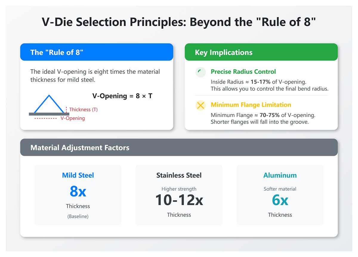
The key parameter of a V-die is its opening width. The well-known “Rule of 8” is an excellent starting point, but true experts know when to follow it and when to adapt.
- Rule Definition and Application: For mild steel, the ideal V-opening is eight times the material thickness. For example, a 3 mm sheet should ideally use a 24 mm (3 mm × 8) V-opening.
- Precise Radius Control: In air bending, the inside bend radius typically equals 15–17% of the V-opening width. This means you can control the final bend radius by adjusting the V-opening width, a subtle advantage unique to air bending.
- Minimum Flange Length Limitation: The shortest possible flange (Minimum Flange Length) is roughly 70–75% of the V-opening width. If the flange is shorter, it will fall into the V-groove and fail to form properly—an essential constraint to consider during design.
- Material Adjustment Factors:
- Stainless Steel: Higher strength requires a larger V-opening to reduce stress, typically 10–12 times the sheet thickness.
- Aluminum: Softer material allows smaller radii; typically six times the sheet thickness.
Beyond the standard single-V die, the Multi-V Die offers a cost-effective boost in efficiency. Featuring multiple V-openings integrated into one body, the operator can easily rotate it to switch sizes—ideal for small-batch, high-variety production environments.
Special Forming Dies: Achieving Efficiency in One Step
When standard V-dies require multiple passes to produce complex shapes, special forming dies enable a true one-step transformation—ushering in an era of efficiency breakthroughs.
- Hemming/Flattening Dies: Working in tandem with sharp-point upper dies, these tools operate in two stages—pre-bending and flattening—to fold sheet edges into a safe 180° seam. This not only strengthens the edges but also eliminates sharp burrs, improving both product quality and operator safety.
- U-Dies: When paired with a large-radius upper die, these dies form U-shaped or channel profiles in a single operation. In contrast, a standard V-die would require two bends to achieve the same shape, effectively doubling productivity.
- Z-Dies: Combined with an offset upper die, they create stepped Z-shaped bends in one stroke—far more efficient than the traditional two-step forming process.
- Curling Dies: Designed to roll sheet edges into circular or tubular forms, these dies are commonly used for decorative edge finishes or hinge fabrication.
2.3 Comparison of Main Tooling Systems: American, European, and the New Standard (WILA)
Press brake tooling systems are primarily categorized by their clamping mechanisms and the geometry of the tang. Today, three major global standards dominate: the American, the European/Promecam, and the New Standard, represented by WILA/Trumpf. These systems are generally non-interchangeable by default, and selecting one over another is a strategic investment that impacts production efficiency, precision, and automation potential.
| Feature | American Style | European / Promecam | New Standard (WILA / Trumpf Style) |
|---|---|---|---|
| Tang Characteristics | Rectangular tang, 1/2 inch (12.7 mm) wide; no special grooves. | Narrow tang, about 13 mm wide, typically includes a safety groove. | Precision tang, 20 mm wide, grooved front and back for self-centering and hydraulic clamping. |
| Clamping Method | Manual set screws or clamping plates. | Manual or mechanical quick-lock lever. | Hydraulic/pneumatic quick clamping with one-touch operation. |
| Changeover Speed & Setup Time | Slow (5–15 min). Requires manual screw tightening and alignment. | Moderate (2–5 min). Faster than screws, though still requires manual positioning. | Ultra-fast (<1 min). Push-button or fully automatic, supports vertical loading/unloading. |
| Accuracy & Repeatability | Moderate. Uneven manual tightening and long-term wear reduce alignment precision. | Good. More stable than American—accepted industry standard. | Exceptional. Self-centering with uniform clamping achieves ±0.01 mm repeatability. |
| Automation Compatibility | Low. Structurally unsuitable for ATC or robotic tool change. | Medium–low. Partial semi-automation possible through upgraded fixtures. | High. Designed for full automation, supports ATC, robotic tool change, and smart tool recognition. |
| Safety & Ergonomics | Basic. No fall-prevention design; tool changes are labor-intensive with safety risks. | Moderate. Some quick-lock systems include basic drop-prevention features. | High. Usually equipped with safety pins or buttons to prevent accidental tool drops; supports one-handed operation. |
| Initial Cost | Low. Simple design and most economical tooling/clamping prices. | Medium. Balanced cost-performance ratio—most widely used worldwide. | High. Precision engineering and rapid clamping mechanisms yield the highest investment cost. |
| Strategic Positioning | Foundation of traditional mass production. Best for large batch jobs with infrequent tool changes. | Backbone of flexible manufacturing. Ideal for high-mix, medium-volume production, balancing speed, accuracy, and cost. | Future of lean manufacturing. Perfect for operations demanding extreme efficiency, precision, and automation—favored in aerospace and high-end electronics industries. |
Conclusion: Choosing a tooling system is essentially casting a vote for your manufacturing philosophy. The American system represents the robust, cost-effective past of mass production; the European system, with its flexibility and value, defines today’s adaptive manufacturing; and the WILA-led New Standard, through unmatched speed, precision, and automation, paves the way for tomorrow’s lean, Industry 4.0 factories. The impact of this decision will echo through every beat of your plant’s operations for the next decade.
III. The Five-Step Decision Framework: A Practical Method for Selecting the Perfect Press Brake Tool
In the previous chapters, we reframed the strategic understanding of press brake tooling and decoded its extensive library. Now it’s time to put theory into practice. Tool selection should never rely on intuition or experience alone—it must follow a disciplined, replicable, scientific decision-making process.
The following five-step framework will guide you from material analysis to long-term investment evaluation, helping you eliminate guesswork and consistently reach the optimal solution that maximizes value with every choice.
For those seeking expert resources and guidance, visit ADH Machine Tool to explore professional press brake solutions.
3.1 Step 1: In-Depth Analysis of Core Material

Every design begins with the material. Before choosing any tooling, you must analyze your core material as meticulously as a materials scientist would. It’s not just about knowing the name and thickness—you need to decode four fundamental “genetic markers” that determine the success or failure of any bending operation.
- Tensile Strength: The Determiner of Required Tonnage — This is the key factor dictating the bending force required. High-strength steels (AHSS) can have tensile strengths several times greater than mild steel, meaning that, at the same thickness, they demand far more bending force and, consequently, tougher, more wear-resistant tooling. Choosing a die solely by thickness and ignoring tensile strength is the number one cause of premature tool wear or catastrophic failure. Always ensure your tonnage charts include tensile strength as a core input variable.
- Yield Strength & Springback: The Angle Control Strategist — A material’s yield strength determines how much it “remembers” its original shape after bending—its springback. Hard materials like stainless steel can spring back 2–3°, while soft aluminum may show virtually none. To achieve a precise 90° bend in high-springback materials, you must overbend slightly using sharper upper dies (e.g., 88° or even 85°) to offset the rebound. Failing to account for springback will leave you forever chasing exact angles and wasting time on repeated trial adjustments.
- Ductility & Minimum Bend Radius: The Crack-Prevention Sentinel — A material’s ductility defines the smallest internal bend radius it can withstand without cracking. A widely cited but often misapplied rule states that the ideal inside radius should roughly equal the material thickness. Forcing a sharp punch to create a radius smaller than this overstretches the outer surface, often producing visible cracks. Therefore, the punch nose radius must be greater than or equal to the material’s minimum bend radius—this is the non-negotiable baseline for product quality.
- Surface Condition: The Guardian of Aesthetic Quality The surface properties of a sheet—whether it has a coating (such as galvanization or paint), a protective film, or a mirror/brushed finish—directly determine its friction behavior against the tooling. When bending mirror-finish stainless steel or anodized aluminum, even the smallest imperfection or friction on the tool can leave a permanent scratch. In these cases, it’s essential to use dies that are highly polished (Ra < 0.2 μm), feature specialized low-friction coatings such as TiN, or employ lower dies with a mark-free protective film. For more technical guidance on surface protection and die coatings, explore the best press brake tooling resources. Such measures are critical to preserving the finished product’s visual perfection.
3.2 Step Two: Precisely Define the Bending Geometry
Once the material characteristics are fully understood, the next step is to translate the geometric requirements on the drawing into the precise language of tooling. This involves accurately defining three core parameters of the bend while applying the “Rule of 8” with flexibility and expertise.
- Bend Angle and Process Selection: This is the most fundamental requirement. Do you need a right angle (90°), an acute angle (<90°), or an obtuse angle (>90°)? The answer directly determines whether you’ll use air bending, bottoming, or coining—and accordingly, how the punch and die angles should be paired.
- Active Control of the Inside Radius: In air bending, the inside radius is not determined solely by the punch tip radius but primarily by the V-die opening width, following the approximate relation: Inside Radius ≈ V-opening × 0.16. This means you can precisely control the final bend radius by selecting dies with different V openings—one of the most elegant capabilities of modern bending technology.
- Rethinking the “Rule of 8” — From Rule to Strategy: The well-known “Rule of 8” (V-opening = 8 × material thickness) is an excellent starting point, but not an unbreakable law. True experts know when to adhere to it and when to adapt:
- Thick Plates (>10 mm): Increase the factor to 10–12× to provide a larger contact surface, distribute stress more evenly, and prevent cracking.
- Soft Materials (e.g., Aluminum): To achieve a smaller bending radius, the factor can be reduced to about 6×.
- Chasing Small Radii: Select a narrower V-die opening, but note that this significantly increases the required tonnage. Always recalculate the tonnage to ensure it remains within both tool and machine capacity limits.
- Minimum Flange Length — A Hard Constraint: The shortest bend edge of a workpiece must be long enough to rest securely on the shoulders of the lower die. The minimum flange length should be approximately 70% of the V-die opening width. If the flange is too short, it will fall into the V-die during bending, preventing proper forming—a critical factor that must be addressed during part design.
3.3 Step Three: Match Tooling and Press Brake Parameters

Tooling does not function in isolation—it operates as part of a tightly integrated system with the press brake. Even the finest die will fail if its parameters do not align with the machine’s specifications, potentially leading to serious safety hazards. This stage is a critical “compatibility test” that allows no margin for error.
| Key Parameter | Matching Considerations & Professional Insights | Severe Consequences of Mismatch |
|---|---|---|
| Rated Tonnage | The bending tonnage must remain strictly below the lower of the tool and machine’s rated capacities, with at least a 20% safety margin. | Catastrophic failure: machine overload causing frame deformation or hydraulic rupture; tool fracture under excessive pressure with flying debris posing fatal risk. |
| Daylight | When the ram is fully raised, the open height between upper and lower tool holders must accommodate tool height, blank size, and clearance for formed flanges. | Production constraint: inability to install taller tools (e.g., gooseneck punches); interference between formed flanges and the crossbeam when producing box-shaped or U-shaped parts. |
| Stroke | The vertical travel of the ram must be sufficient to complete bending and provide enough clearance for material handling afterward. | Efficiency bottleneck: insufficient stroke for deep U-channels or high flanges prevents full punch entry or traps the part in the die, severely disrupting cycle time. |
| Clamping System | The tool’s shank type (American, European, WILA, etc.) must be fully compatible with the press brake’s upper and lower clamping systems. | Loss of both accuracy and safety: improper installation, die movement during operation, loss of precision, or dangerous stresses from forced adapters. |
3.4 Step Four: Evaluate Tool Material, Hardness, and Coating
The intrinsic quality of tooling depends on its base material, heat treatment, and surface coating. These factors directly influence its lifespan, ability to maintain precision, and overall cost. This step represents a deep examination of the tool’s inner strength and durability.
- Choosing the Core Material: Balancing Toughness and Wear Resistance
- 42CrMo: The versatile all-rounder. With proper heat treatment, it achieves a hardness of HRC 47±2, offering an excellent balance between toughness and wear resistance. It delivers great cost performance and is the go-to material for most medium-strength bending applications.
- Cr12MoV: The “wear-resistance specialist.” Its high carbon and chromium content yield superb hardness (up to HRC 60) and exceptional wear resistance, making it ideal for mass production or for bending stainless steels and other high-hardness materials.
- Carbide: The “ultimate champion.” Boasting extreme hardness and durability, it lasts tens of times longer than regular steels. However, it is costly and brittle, so it’s reserved for high-precision applications such as forming microelectronic components where dimensional accuracy and lifespan are paramount. For detailed comparisons of tool materials and coatings, see our best press brake tooling guide.
- Hardness (HRC) Is Not Always Better — The Toughness Paradox
A crucial insight: hardness determines wear resistance, while toughness determines impact resistance. Excessive hardness sacrifices toughness, making the tool brittle and more prone to catastrophic fracture under shock or overload. The ideal hardness should match the strength of the processed material, offering sufficient wear resistance without compromising durability under dynamic loads. - The Strategic Value of Coatings: Performance Multipliers If the material is the “skeleton” of the tool, then coatings serve as its “catalyst” and “armor.”
- TiN (Titanium Nitride): The classic golden coating that significantly boosts surface hardness, reduces friction, and prevents material adhesion—particularly when bending aluminum or stainless steel—effectively extending tool life.
- DLC (Diamond-Like Carbon): With ultra-low friction and high hardness, DLC coatings are the premium solution for processing non-ferrous metals, preventing scratches, and minimizing material sticking.
3.5 Step Five: Balancing Initial Investment and Long-Term Value (LTV)
This final step requires a strategic mindset shift—from a buyer’s cost perspective to a business leader’s investment perspective. The cheapest die is often the most expensive one in production. Decisions should be guided not by the upfront purchase price (Initial Cost) but by the tool’s Total Cost of Ownership (TCO) and the Long-Term Value (LTV) it creates throughout its lifecycle.
TCO/LTV Evaluation Framework: Making Hidden Costs Visible Through Data
| Evaluation Dimension | The Hidden Price of Cheap Dies | The Long-Term Returns of Premium Dies |
|---|---|---|
| Setup and Calibration Time | Low precision requires repeated trial bends and adjustments, adding over 30 minutes of downtime per tool. | High precision ensures plug-and-play performance—success on the first try—cutting setup time from hours to mere minutes. |
| Scrap and Rework Rate | Unstable angles and surface scratches drive a 5–10% scrap rate—pure waste of material, labor, and energy. | Consistent bend accuracy reduces scrap to under 1%, directly improving profitability and first-pass yield. |
| Die Life and Replacement Frequency | Poor materials wear out quickly, lasting only a few thousand cycles and requiring frequent repurchases—raising total procurement costs. | Premium materials and heat treatment guarantee hundreds of thousands of cycles—a one-time investment with enduring benefits. |
| Machine Wear | Inaccurate dimensions or flawed design cause uneven stress and overloads, accelerating component wear and shortening overhaul intervals by 20%+. | Perfect machine compatibility distributes loads evenly, offering the best protection for multimillion-dollar equipment investments. |
| Production Safety | High risk of cracking or fracturing, posing serious threats to operators—one accident could cripple a business. | Reliable materials and safe design eliminate die-failure hazards at the source—delivering true people-first protection. |
By applying this five-step decision framework, you elevate die selection from a vague purchasing act to a data-driven strategic decision. This approach not only leads you to the right tooling but also fundamentally optimizes production processes, eliminates hidden costs, and builds an unshakable manufacturing advantage in a fiercely competitive market. To explore high-performing dies that align with these principles, check out the best press brake tooling available through ADH Machine Tool.
IV. Asset Protection and Performance Enhancement: Maintenance, Troubleshooting, and Optimization
4.1 Installation and Calibration: The Foundational Ritual of Precision
Nearly 90% of bending accuracy issues stem not from the machining process itself but from the often overlooked “initial ritual” of installation and calibration. Any minor oversight at this stage can be magnified exponentially by bending pressure, resulting in irreversible quality defects down the line.
1. Cleanliness: The Non-Negotiable First Commandment Before installing any die, all contact surfaces—including tool shanks, upper and lower clamps, and the worktable—must be thoroughly cleaned with lint-free cloth and approved solvent. This is not mere formality but a necessity of physics: under hundreds of tons per meter, even a tiny metal chip or thin oil film can leave permanent impressions on the die or clamp. These invisible defects destroy alignment precision and become the root cause of all subsequent deviations.
2. Standardized Installation Sequence: The Discipline of Eliminating Cumulative Error Precise alignment is never accidental—it’s the inevitable result of following a correct procedure.
- Bottom First, Then Top – Using Gravity for Alignment: Begin by installing the lower die and lightly secure it so it can still fine-tune laterally. Then mount the upper punch and slowly lower the ram until the punch tip naturally rests in the center of the lower die’s V-groove by its own weight, achieving preliminary physical alignment.
- Lock with Pressure, Tighten from Center Outward: Continue lowering the ram to apply slight pressure (around 1–2 tons) so the dies fully mate. Then, strictly follow a “center-to-ends” tightening sequence for all upper and lower clamps. This sequence is deliberate—it eliminates accumulated tolerances between die segments and ensures even load distribution across the entire tool line.
3. Crowning Compensation: A Precise Battle Against Physical Deformation Crowning compensation represents the most technically demanding and operator-dependent step in press brake calibration. Every press brake inevitably experiences elastic deflection under load—the ram and bed bow upward like an arch, making the bend angle at the center larger than at the ends (the “canoe effect”). The purpose of the crowning system is to apply an accurately calculated counter-deflection to perfectly neutralize this distortion.

- Manual Crowning Calibration: The Operator’s True Test
- Select a test piece covering at least 80% of the bed length and perform a 90° trial bend.
- Measure the bend angle at both ends and at the center using a precision angle gauge.
- If the center angle is larger than the ends (e.g., 92° in the center versus 90° at the ends), compensation is insufficient and must be increased.
- Repeat the test and measurements, fine-tuning until the angle deviation along the full workpiece length stays within the tolerance range (e.g., ±0.5°).
- Understanding the Principle Behind CNC Automatic Crowning Modern CNC press brakes can automatically calculate and apply compensation values, but that doesn’t mean the operator can ignore the underlying mechanics. Grasping the logic of manual calibration equips you to diagnose and correct issues when the automated system drifts—transforming you from a passive user into an active troubleshooter.
4.2 Preventive Maintenance and Service Life Extension Strategies
Structured preventive maintenance is the only way to replace costly unplanned downtime with low-cost scheduled upkeep. It maximizes die lifespan and ensures stable, high-quality output throughout every day of its operational life cycle.
| Maintenance Interval | Core Tasks | Asset Value |
|---|---|---|
| Daily / Each Shift | Cleaning, Inspection, and Oiling: After each use, wipe the dies with a lint-free cloth and anti-rust oil. Visually check for chipping, scratches, or indentations. | Eliminate hazards. Prevent corrosion, detect early damage, and stop defective dies from entering the next production batch—cutting off scrap at the source. |
| Weekly | Lubrication and Tightening: Lubricate moving components such as guide rails and lead screws. Inspect and re-torque all die-clamping bolts to specification. | Stabilize performance. Ensure smooth machine operation and prevent abnormal die wear or dimensional drift due to loosening. |
| Monthly | Detailed Inspection and Measurement: Use calipers, radius gauges, and angle rulers to measure wear on critical die features (V-width, tip radius, angles). | Predict lifespan. Quantify wear trends, providing data for procurement planning and shifting from reactive replacement to proactive strategy. |
| Annually / Every 2000 Hours | Professional Calibration and Overhaul: Have qualified technicians perform a full machine alignment—including parallelism, crowning system calibration, and precision checks. | Reset the baseline. Restore original machine accuracy, laying the foundation for another production cycle—an essential measure to safeguard multimillion-dollar equipment investments. |
Storage Strategy: The Overlooked Value Reservoir Incorrect storage practices can severely degrade the performance of even the highest-grade tools within weeks.

- Dedicated Storage—No Stacking: Store each tool set on a designated rack, ensuring that molds never touch or stack against one another. This prevents accidental scratches or dents on working surfaces.
- Apply Rust-Proof Oil—Keep Moisture Out: For long-term storage, clean the mold thoroughly and apply a light layer of anti-corrosion oil. Store it in a dry, temperature-controlled environment to prevent rust and humidity damage.
- Digital Archive Management: Assign every mold an identification record—its model, dimensions, purchase date, usage count, and maintenance history. Beyond simplifying management, this database becomes invaluable for tracing quality issues and optimizing future mold selection.
4.3 Common Bending Defect Troubleshooting: Become the Detective of Your Production Line
When faced with bending defects, seasoned operators diagnose problems much like doctors—by observing, inspecting, and reasoning to pinpoint the root cause. The following guide outlines a systematic diagnostic workflow.
| Defect Symptom | Probable Root Cause (in descending likelihood) | Diagnostic and Corrective Actions |
|---|---|---|
| Inconsistent Angles (larger in middle, smaller on ends) | 1. Insufficient deflection compensation: the most common cause; the press’s center deformation isn’t fully offset. 2. Mold center wear: repeated bending at the same position causes localized wear. 3. Overload tonnage: exceeding rated capacity produces excess deformation. | 1. Increase deflection compensation and re-bend for measurement. 2. Rotate the die 180° or replace the worn section. Expert tip: alternate bending positions across the worktable to achieve uniform die wear. 3. Recalculate bending tonnage; consider using a wider V-die to reduce required pressure. |
| Excessive or unstable springback | 1. Material properties: high-strength or stainless steels inherently produce more unstable springback. 2. Oversized V-opening: too wide compared to sheet thickness reduces forming restraint. 3. Bending process: air bending naturally relies on springback control. | 1. Overbend: program a slightly sharper angle than target (e.g., bend to 88° for a desired 90°). 2. Switch to a narrower V-die (note: tonnage increases significantly; recalculate load). 3. Adopt bottoming—force the sheet into the die for more complete forming and less springback. |
| Cracks at the outer bend root | 1. Bend radius too small: punch tip radius below the material’s minimum allowable radius leads to over-stretching. 2. Bend line parallel to rolling direction: stress concentrates along weaker grain areas. 3. Damaged punch tip: burrs or chips act as stress concentration points. | 1. Replace with a punch having a larger tip radius—this is the only true fix. 2. During layout, orient bend lines 45° or 90° relative to rolling direction. 3. Inspect and polish or replace the punch immediately. |
| Surface scratching (Die Marks) | 1. Contaminated die surface: debris, dust, or rust on V-die shoulders. 2. Worn rough shoulders: long-term use makes shoulders abrasive like sandpaper. 3. Excessive friction between material and die: common when bending aluminum, stainless steel, or coated sheets. | 1. Clean die thoroughly with compressed air and a lint-free cloth before each use, especially shoulder areas. 2. Polish die shoulders or replace the lower die. 3. Optimal solution: use scratch-free bending film (UHMW-PE) or invest in dies with roller-bearing shoulders. |
| inaccurate flange length | 1. Misaligned backgauge: calibration errors, mechanical looseness, or servo missteps. 2. Sheet slippage or improper contact: often occurs with oily, warped, or smooth material surfaces. 3. Material distortion during bending: narrow, long parts may bow or bend irregularly. | 1. Calibrate backgauge X- and R-axes; tighten all mechanical joints. 2. Ensure sheet and backgauge fingers are clean and oil-free; refine feeding technique for full contact every time. 3. Use backgauge fingers with support arms or include deformation compensation in programming. |
By implementing this comprehensive asset management system—from installation to troubleshooting—your press brake tooling ceases to be a consumable and instead becomes a durable strategic asset. Every measure of care you invest will return in higher product quality, lower operating costs, and stronger market competitiveness.
V. Conclusion
Our exploration of the “best press brake tooling” transcends mere brand or model recommendations; it establishes a strategic, enterprise-level framework. We redefine tooling as a core asset balancing precision, efficiency, and total cost of ownership rather than a disposable consumable.
Through in-depth analysis, we decode tooling types—from punches and dies to clamping systems (detailed specifications are available in our Brochures)—and present a five-step scientific decision process encompassing material analysis, bending geometry, ensuring compatibility with your press brake, tool material and coating evaluation, and cost-value balance.
Asset protection via proper installation, preventive maintenance, and troubleshooting is emphasized to ensure longevity and consistent production quality. This holistic approach transforms tooling selection into a strategic pillar of manufacturing excellence, shifting the focus from purchasing tools to investing in valuable production assets. To navigate this strategic process and optimize your investment, contact us for an expert consultation.


