I. Introduction
In the modern metal fabrication industry, a press brake machine is an indispensable piece of equipment for processing metal sheets. Its properties directly affect the precision and quality of the products.
In numerous bending technologies, press brake crowning is the key to ensuring the accuracy of the bending. But what is press brake crowning? Crowning is a technology designed to offset the uneven bending caused by machine tool, die, and material elastic deformation.
In brief, it can adjust the shape of the upper punch and bottom die properly during the bending to ensure the bending angle is consistent throughout the bending length, thus improving the precision and quality of the workpiece.
II. Definition, Purpose, and Importance of Crowning
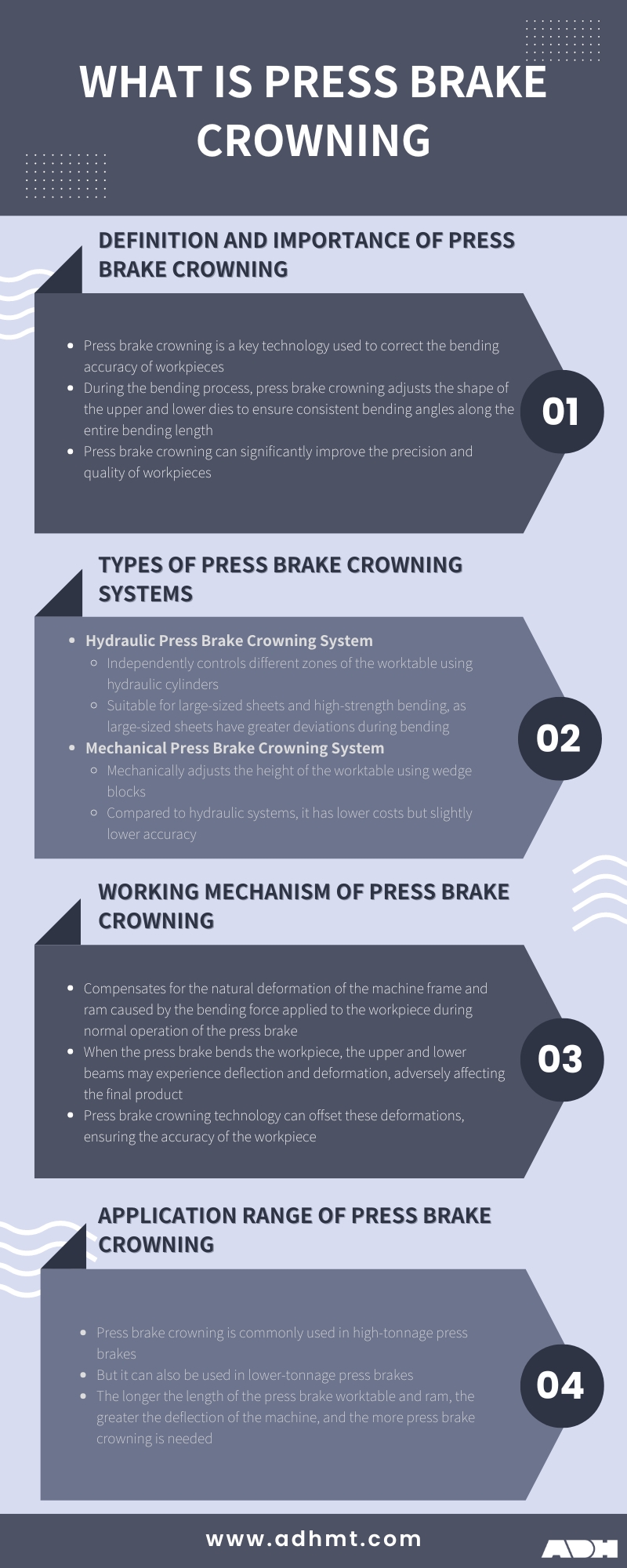
2.1 Unveiling the “Canoe Effect”: Why a Press Brake Appears to “Smile”
When a press brake exerts hundreds of tons of force to bend a metal sheet, the machine itself also bears significant stress. This stress causes a subtle yet critical physical deformation (deflection) in the machine’s frame—especially in the central region where structural support is weakest.
- Core Challenge: Machine Frame Deformation
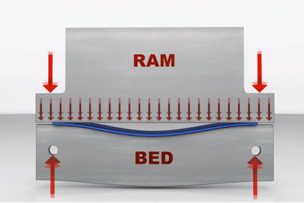
Under such enormous pressure, both the upper beam (Ram) and lower beam (Bed) tend to bend outward, much like a wooden plank sagging under a heavy load. Because most press brakes are powered and supported at their side frames, the center becomes the structurally weakest point, leading to the most visible deflection there.
- Visual Explanation: The “Smiling” Press Brake and the Canoe-Shaped Workpiece
This characteristic curve—with a slight dip in the center and raised ends—resembles a “smile.” When the upper and lower dies press the workpiece along this smiling curve, the center receives less penetration than the ends. As a result, the bend angle in the center is larger (more obtuse) than at the ends, producing a cross-section shaped like a canoe—wide in the middle and tapered at both ends. Hence the term “Canoe Effect.”
- Two Main Sources of Deformation
Operators often focus solely on the deflection of the beams but tend to overlook another contributing factor:
- Bending of the Bed and Ram: The most intuitive form of deformation—direct deflection of the upper and lower beams themselves.
- Side Frame “Opening” Effect: The side frames (usually C-shaped) experience a slight elastic opening under load. This “opening” increases the distance between the upper and lower beams at the center, amplifying the Canoe Effect even more.

2.2 What Is Press Brake Crowning?
Crowning is a specialized technique designed to counteract the deformation described above.
- Authoritative Definition
Crowning is a system that introduces a precisely controlled convex curve into the press brake’s lower bed or upper ram—opposite in direction to the expected deformation under load. This proactive adjustment “pre-bends” the machine so that, when bending force is applied, the die gap remains perfectly parallel along the entire length.
- Illustrative Analogy: Creating a “Frown” for a Perfectly Straight Result
If the press brake naturally “smiles” under pressure (forming a downward curve), crowning effectively makes the machine “frown” (introducing an upward curve) before the load is applied. Once the bending force is exerted, the pre-set “frown” precisely cancels the natural “smile,” ensuring that the die contact line stays perfectly straight.
- Core Objective
The fundamental goal of crowning is to maintain uniform bending pressure across the entire length of the workpiece, resulting in consistently accurate angles from end to end.
2.3 Why Crowning Is an Indispensable Feature of Precision Bending
In today’s high-precision, high-efficiency manufacturing environment, crowning is no longer optional—it’s essential. Ignoring it directly leads to spiraling quality and cost issues.
- Quantified Value: A Leap from ±2° to ±0.25°
Without effective crowning, a typical defect manifests as larger angles in the center and smaller ones at the ends of a workpiece. For long parts, this variance can reach ±2° to ±3°. Modern CNC crowning systems, however, can reduce total angle deviation to ±0.25°, achieving an 80–90% improvement in angular consistency. This precision is critical for industries such as aerospace, medical equipment, and high-end architectural panels.
- The Cost Trap: Scrap, Rework, and Lost Time
Without crowning, operators must rely on outdated trial-and-error methods like shimming—inserting paper or metal layers to compensate manually. This approach creates excessive waste, increases rework hours, and drastically prolongs setup time. Studies show that deflection-related quality issues can account for 15–20% of sheet metal rework costs. Investing in an efficient crowning system typically pays for itself within 12–18 months through reduced scrap and higher productivity.
- Fundamental Assurance: The Only Reliable Engineering Solution
For workpieces longer than 1 meter (approximately 3 feet) or materials requiring massive tonnage—such as high-strength steel—deflection is inevitable. In these cases, crowning is the only engineering solution that truly ensures uniform bending angles. Whether mechanical or hydraulic, modern crowning systems provide predictable, repeatable, and precisely controllable compensation unattainable through manual adjustments. Crowning transforms bending accuracy from an “art” into a “science.”
2.4 Compensating for Deflection
In order to improve bending accuracy and eliminate bending angle errors caused by ram and workbench deformation, it is necessary to compensate for their deflection.
Press brakes can be equipped with a crowning system or compensation to generate an opposite force that balances the deflection of the ram and the workbench.
This machine crowning system is usually installed for large sheet metal and high-strength bending because the deflection error of large sheet metal bending is relatively large.
2.5 Purpose of Press Brake Crowning
The main goal of press brake crowning is to achieve accurate and uniform bends, which is essential for several reasons:
Ensuring Accuracy
Crowning ensures the finished product meets specifications by compensating for the press brake's deflection. This precision is crucial for parts that need to fit together correctly and maintain dimensional accuracy.
Reducing Defects and Scrap Rates
By preventing defects like bowing or twisting, crowning reduces scrap rates and minimizes the need for costly rework. This improves productivity and enhances the overall quality of the products.
Maintaining Uniform Bending
Crowning ensures the bending force is evenly distributed across the workpiece, resulting in a uniformly bent product. This is particularly important for thicker or longer materials, where inconsistencies can be more pronounced.
Enhancing Precision and Quality
Modern press brakes often use programmable crowning systems that adjust for specific parameters such as sheet thickness, length, die opening, and material tensile strength. These systems achieve accurate bends with minimal operator input, ensuring high-quality results and efficient operation.
2.6 Importance
Before the invention of the compensation system, some press brake manufacturers used convex worktables to control crowning, but the compensation was less accurate.
With the improvement of the CNC system, the crowning system is now controlled by the CNC system, which is called the CNC crowning system. Therefore, the operator only needs to input the length, thickness, bending angle, and other information about the bending.
The crowning system will automatically calculate the compensation values. The system can store this information and directly reuse the data during the next repeated bending procedure.
The crowning system improves the bending accuracy and efficiency of small-batch workpieces. For large tonnage and high-strength bending, the accuracy of the bending angle can be guaranteed.
Crowning includes compensating for natural deformation and bending that occur in the base and ram of the press brake during normal operation due to the bending force applied to the workpiece.
When a bending machine bends the workpiece, both the upper and lower crossbeams may suffer deflection and deformation, which may have unwanted effects on the final product.
By effectively mastering press brake compensation, operators can ensure accurate bending, thereby reducing waste in the manufacturing process and improving productivity.
Ⅲ. In-Depth Analysis of the Four Major Crowning Systems: From Manual to Intelligent—How to Choose the Right One
Once you understand why crowning compensation is essential, the next step is to choose the right “weapon.” The market offers a wide range of technologies—from rudimentary manual adjustments to sophisticated intelligent closed-loop control systems. Each represents a different stage in the evolution of bending technology and corresponds to distinct production demands, precision levels, and investment return models. Making an informed decision for your factory is the first step toward precision manufacturing.
3.1 The Four Technical Schools of Crowning Compensation: A System Overview
We will examine four mainstream systems in depth. Manual Shimming, the earliest method, relies entirely on operator expertise—thin metal shims are inserted beneath the die holder to offset deformation. Because of its low accuracy, unreliability, and inefficiency, it has largely been phased out in modern precision manufacturing and will not be discussed as a mainstream option. Instead, our focus will be on three industrially relevant systems and their evolution:
- Mechanical Crowning: A robust and durable solution that creates a compensation curve using a set of precisely machined wedge blocks.
- Hydraulic Crowning: Uses the thrust of hydraulic cylinders for fast, precise compensation, often integrated with a CNC system for automated adjustment.
- CNC Dynamic/Adaptive Crowning: The gold standard of crowning compensation, using real-time sensor feedback to continuously adjust deformation through closed-loop control.
3.2 Mechanical Crowning: The Art of Precision Wedge Design
Mechanical crowning remains one of the most widely used and mature technologies. Its core lies in the ingenious wedge block design—a true feat of mechanical craftsmanship.
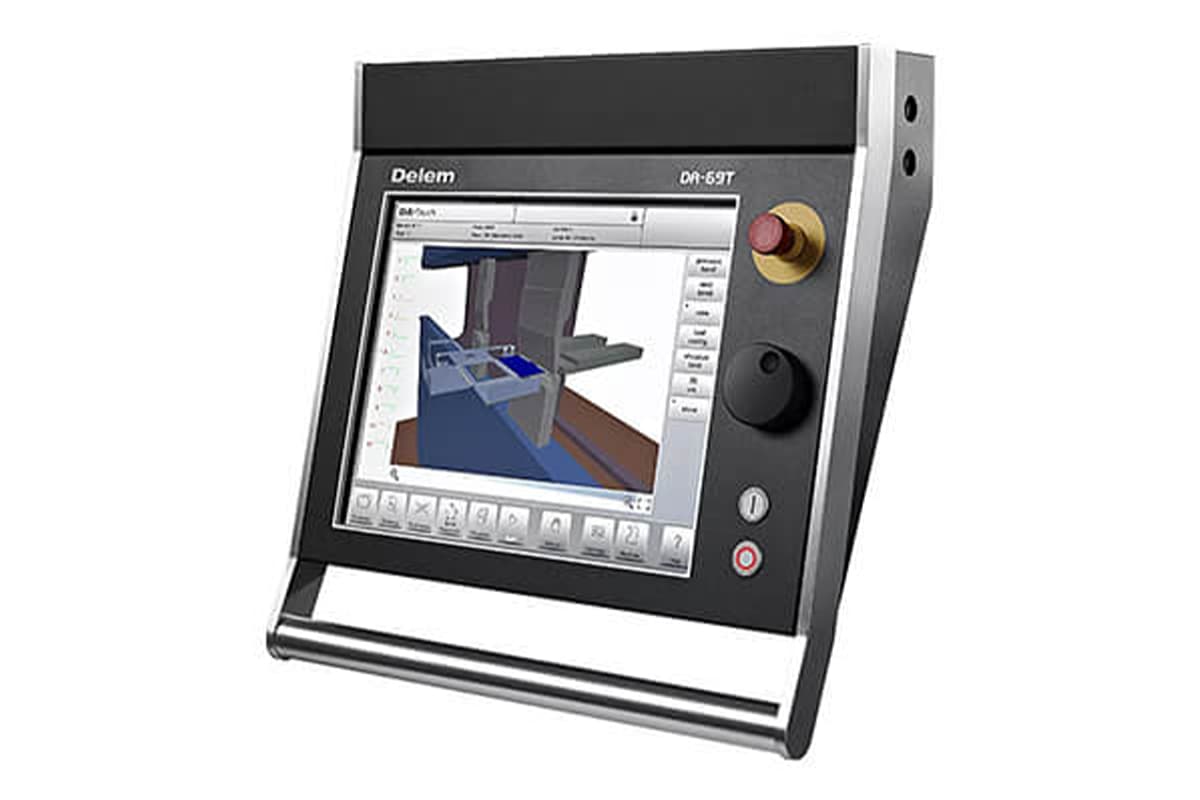
- Working Principle The system consists of a series of precisely machined, oppositely angled wedge blocks mounted within the lower table. When adjusted—either manually via a hand crank or by motor—the wedges slide laterally relative to one another. Thanks to their calibrated inclination, this lateral movement is translated into precise vertical displacement, creating a smooth, uniform upward curve along the entire table length to counteract machine deflection. The compensation effect is global, covering the full working length.
- Advantages
- Stable structure and high repeatability: With a purely mechanical design free from temperature-dependent fluctuations like hydraulic oil, once set, the compensation curve remains extremely consistent and reliable—especially advantageous for repeat production of identical parts.
- Low maintenance cost: Simple mechanical structure with minimal risk of failure. Routine maintenance involves cleaning and lubrication, resulting in low long-term operating costs.
- Disadvantages
- Slow adjustment: Whether manually or motor-driven, adjustment is considerably slower than hydraulic systems, making it less suitable for flexible manufacturing where materials and thicknesses change frequently.
- Fixed compensation curve: The shape of the mechanically generated curve is preset and cannot be fine-tuned locally like advanced hydraulic systems can.
- Ideal Applications Best suited for production environments with stable plans and consistent materials or thicknesses. A cost-effective choice for medium-scale production where reliability and durability outweigh the need for flexibility or speed.
3.3 Hydraulic Crowning: Harnessing the Precision of Fluid Power
Hydraulic crowning brings the precision control of fluid mechanics into the bending process, achieving the perfect balance between speed and accuracy. It is now the standard configuration for modern high-efficiency press brakes.
- Working Principle Multiple (or a single) small hydraulic cylinders are integrated into the lower table. Based on inputs such as sheet thickness, length, tensile strength, and V-die width, the CNC controller uses an internal mechanical model to calculate the required compensation tonnage. It then sends commands to proportional valves, precisely regulating oil pressure to the cylinders. These cylinders apply controlled upward force along the table to produce a compensation curve equal and opposite to machine deflection. The entire process completes automatically within seconds.
- Advantages
- Fast adjustment and high accuracy: Compensation values are generated and applied instantly by the CNC system without manual intervention, drastically reducing setup time and boosting productivity.
- Local compensation capability: A lesser-known advantage of high-end multi-cylinder hydraulic systems (compared to single-cylinder or mechanical designs) is their ability to apply varied lift forces across different zones of the table. This produces non-linear compensation curves closely matching real loading conditions—ideal for handling off-center loads or irregularly shaped parts.
- Disadvantages
- Higher initial cost: Incorporating independent hydraulic units, proportional valves, and complex control integration makes it considerably more expensive than mechanical systems.
- Requires professional maintenance: Sensitive to oil cleanliness, temperature, and system sealing. Risk of leaks and relatively complex upkeep.
- Ideal Applications Suited for high-throughput, high-efficiency production environments—especially flexible manufacturing involving frequent changes in material type, thickness, or bending length.
3.4 CNC Dynamic Crowning: The Gold Standard of Closed-Loop Control
This represents the pinnacle of crowning compensation technology, advancing from preset (open-loop) control to real-time adaptive (closed-loop) correction—the definitive route to ultimate precision.
- Working Principle Beyond the hydraulic system’s quick responsiveness, this method incorporates a closed-loop feedback network. Strain gauges, displacement sensors, or laser angle meters installed at key machine points continuously monitor actual deformation or bending angles during the millisecond-scale bending process. The CNC controller compares these real-time signals against target values, then dynamically fine-tunes hydraulic cylinder pressure, achieving the ultimate goal of concurrent bending, measurement, and compensation.
- Advantages
- Highest precision: This system compensates not only for predictable machine deflection but also for unpredictable variables such as sheet thickness variation, tensile strength fluctuation within a single plate, or thermal deformation caused by ambient temperature shifts—factors beyond the reach of any other system.
- Minimal operator involvement: Highly automated and self-correcting, the system greatly reduces reliance on operator skill or experience—an essential foundation for fully automated, “lights-out” bending cells.
- Disadvantages
- Highest cost: Incorporates premium sensors, powerful control units, and advanced software algorithms, making it the most capital-intensive option.
- Complex technology: Requires precise calibration and specialized maintenance for sensors, with professional service support essential.
- Ideal Applications Industries demanding extreme precision—such as aerospace (wing skins), precision electronics enclosures, and medical devices. It is also the optimal choice for production lines pursuing maximum automation with minimal manual intervention.
3.5 [Ultimate Comparison Table] A Comprehensive Overview of the Four Major Crowning Systems: Make an Informed Choice
| Feature | Manual Shimming | Mechanical Crowning | Hydraulic Crowning | CNC Dynamic Crowning |
|---|---|---|---|---|
| Adjustment Accuracy | Low, unreliable | High | Very high | Highest (closed-loop adaptive) |
| Adjustment Speed | Very slow (minutes) | Slow to moderate (manual/motor-driven) | Fast (seconds) | Real-time (milliseconds) |
| Repeatability | Low | Very high | High | Highest |
| Initial Cost | Almost zero | Medium | High | Very high |
| Maintenance Complexity | None | Low | Moderate (hydraulic system) | High (sensors and control system) |
| ROI (Return on Investment) | Extremely low (major efficiency loss) | High for stable, uniform production | High for multi-part, precision production | Highest for ultra-precision and automation |
| Ideal Application | Emergency, non-precision single-piece repair | Medium- to large-batch runs with fixed material/thickness | Multi-material, high-efficiency, high-precision production | Aerospace, automated lines, extreme-tolerance operations |
Ⅳ. Practical Operation Manual: Calibrating, Using, and Maintaining Your Crowning System
Once you’ve mastered the theory and selected the right system, the real challenge lies in precise day-to-day operation. A skilled operator can unlock up to 95% of a press brake’s potential—and expert-level use of the crowning system is at the heart of that performance. This manual eliminates vague theory and takes a hands-on approach, guiding you through the full cycle—from diagnosis to maintenance—to ensure every bend approaches perfection.
4.1 Step One: Accurate Diagnosis—The Foundation of All Calibration
A wrong diagnosis is worse than no diagnosis at all—it only drives you further down the wrong path. Before attempting any adjustment, you must scientifically and precisely assess your machine’s current deflection state, just like a doctor examines a patient before prescribing treatment.
- Essential Tool Kit
- Precision Straight Edge or Ruler: Should cover at least 80% of the bed length to check die straightness.
- Feeler Gauges: 0.01mm accuracy, for inspecting die gaps and wedge alignment.
- Digital Angle Gauge: Minimum accuracy of 0.1°, your primary device for evaluating bend quality.
- Test Material of Adequate Length: Use material similar in type and thickness to your production parts, ideally spanning about 80% of the bed to clearly reveal deflection patterns.

- The Gold Standard: The “Three-Point Bending Test”
This is widely recognized across the industry as the most direct and reliable method for quantifying the effectiveness of crowning compensation. It replaces guesswork with measurable data, leaving no room for doubt.
- Preparation: Select a flat, uniform test sheet and set a common bend angle (e.g., 90°). Ensure both the upper and lower dies are clean and in good condition.
- Bending: Perform a full bending operation using your normal tonnage and speed settings.
- Measurement: Using the digital angle gauge, measure actual bend angles at three points—the left end (about 10 cm from the edge), the center, and the right end (10 cm from the edge). Record each value precisely.
- Interpretation:
- Center angle > End angles (e.g., ends 89.8°, center 91.5°): This is the classic “canoe effect.” The middle bulges upward because the machine’s center deflects too much—indicating insufficient crowning compensation.
- Center angle < End angles (e.g., ends 90.5°, center 89.0°): The middle sags like a bridge—the crowning force is excessive, resulting in over-compensation.
- Angles nearly identical across all three points (variation within ±0.5°): Congratulations—this means your current crowning setting is essentially correct, with no major adjustment required.
4.2 Step Two: Detailed Procedure for Proper Crowning Adjustment
Based on the results of the Three-Point Test, it’s time to make precise, surgical-grade corrections.
— Mechanical System Adjustment Guide —
- Analyze Results: If the test shows "under-compensation," increase the correction (turn the handwheel clockwise or raise the motor setting). If "over-compensation" occurs, reduce the correction amount.
- Adjust Gradually: This is the essence of mechanical adjustment—small steps, progressive, and symmetrical. Never attempt to fix everything in one move; that often leads to over-compensation. Adjust wedges evenly from the center outward, or turn the handwheel slowly.
- Record Each Turn/Increment: Keep a record of the handwheel turns or control value changes. This habit ensures traceable and repeatable adjustments.
- Re-Test: After every adjustment, use a new test sheet and repeat the Three-Point Test. This rigorous iterative verification ensures uniform angles before final confirmation.
- Hydraulic/CNC System Setup Guide
- Input Core Parameters: In the CNC controller, accurately enter or select the material type (e.g., mild steel, stainless steel), tensile strength (UTS), sheet thickness, bend length, and die V-opening width. These are the bases for automatic calculations—any entry error will result in faulty compensation.
- Trust the Auto Calculation: Modern CNC systems use built-in material databases and mechanical models to automatically compute the required crowning pressure. In most cases, the result will be nearly ideal.
- Fine-Tune for Perfection: If small deviations remain after testing, don’t change the base parameters. Instead, use the controller’s “Crowning Adjustment” or similar interface to fine-tune the compensation value either by percentage or absolute amount. For example, if the center angle is still 0.2° larger, increase the compensation by about 5% or add a small incremental value.
- Save the Program: Once the ideal result is achieved, save the program with the final compensation values under a clear, practical name (e.g., “3mm-SS-8V-3m-90deg”). This turns your hard-earned calibration into a permanent efficiency booster.
4.3 Step Three: Think Systemically—Beyond Individual Adjustments
This is what sets expert technicians apart from ordinary operators: a systems-thinking mindset. Treat crowning compensation not as an isolated fix, but as one integral part of the entire bending process chain.
Insight #1: The crowning system is part of an integrated process, not an isolated function. Even the most finely tuned crowning setup cannot produce qualified parts if other steps in the bending process are flawed. Before suspecting the crowning system, rule out the following “usual suspects”:
- Tool wear: Uneven wear of the upper and lower dies—especially heavy center wear from frequent bending of small parts—can cause angle deviations that closely resemble insufficient crowning compensation. Before adjusting crowning values, inspect and replace worn tools using a precision straightedge.
- Backgauge parallelism: The backgauge must remain perfectly parallel to the bending beam. If not, even consistent bend angles will result in varying flange dimensions along the part—a critical quality defect.
- Ram-to-bed parallelism: This represents the machine’s most fundamental mechanical accuracy. Before performing any crowning calibration, ensure that the ram and bed are parallel under no-load conditions according to the manufacturer’s specification.
- Material stress and thickness variations: Even within the same sheet, minor differences in thickness and tensile strength can change springback and required tonnage. This is where CNC dynamic crowning systems truly shine—by compensating for these variables in real time.
- Performance verification and database creation: After producing a perfectly formed workpiece, don’t rush to the next job. Carefully record all parameters—including final crowning values—and build your own bending process database. This valuable resource will drastically reduce setup time for similar parts and transform personal expertise into organizational knowledge.
4.4 Step Four: Preventive Maintenance—Sustaining Peak Performance
Even the best system requires care. Regular preventive maintenance is essential to keep the crowning system consistently precise—it helps avoid up to 90% of sudden failures.
– Mechanical System Maintenance Checklist –
- Weekly: Clean exposed screws and guides of the wedge adjustment mechanism, then apply the recommended grease to prevent dust and chips from causing jamming or wear.
- Every 3–6 months: Remove the tooling and clean the table and wedge surfaces thoroughly. Check for abnormal wear or indentations on wedges. Use feeler gauges to inspect contact and alignment between wedges.
- After machine relocation or major overhaul: Always perform the “three-point bending test” again to verify wedge positions and compensation accuracy across the entire table.
– Hydraulic System Maintenance Checklist –
- Daily: Before starting the machine, visually check the hydraulic lines, joints, and cylinder seals for leaks. Verify that oil levels and temperatures in the tank are within the normal range.
- Every 500–1000 hours: Replace hydraulic filters as recommended by the manufacturer to maintain clean oil—this is vital to the longevity of proportional valves and cylinders.
- Annually: Have a certified service engineer perform a professional pressure calibration to ensure that the proportional valve output precisely matches the CNC-set pressure values.
– Dynamic System (Sensor) Maintenance Checklist –
- Weekly: For systems with laser angle measurement, gently clean transmitter and receiver lenses using special lens wipes and cleaner to prevent dust or oil from affecting accuracy.
- Annually: Ask the manufacturer or authorized service provider to conduct a professional calibration of all sensors—whether strain gauges or displacement sensors—to ensure absolute reading accuracy and maintain closed-loop reliability.

Ⅴ. Advancement and Pitfall Avoidance: The Path from Skilled Technician to Expert
Once you’ve mastered operation and maintenance fundamentals, you’re a skilled technician. But to become a true expert, you must diagnose complex issues, debunk industry myths, and extract insight from both successes and failures. This chapter completes your journey—it reveals the deeper logic behind problems and helps you make wiser technical decisions.
5.1 Diagnosing and Eliminating the Root Causes of Common Bending Defects
Experts never adjust blindly when facing defective parts. Like seasoned physicians, they identify symptoms and trace them to root causes. This quick diagnostic chart is your essential “stethoscope.”
| Defect Issue | Visual Appearance | Core Diagnosis and Primary Action |
|---|---|---|
| Center under-bent, ends over-bent | The middle of the part is “bulged,” resembling a canoe—center angle is larger (blunter) than at the ends. | Diagnosis: Insufficient crowning compensation. This is the most typical sign that deflection has not been fully counteracted. Action: Increase crowning compensation. |
| Center over-bent, ends under-bent | The middle of the part is “sunken,” like a small bridge—center angle is smaller (sharper) than at the ends. | Diagnosis: Excessive crowning compensation. The applied force exceeds the machine’s actual deflection. Action: Reduce crowning compensation. |
| Irregular angle fluctuations | Bend angles vary randomly along the part, with no clear pattern or forming a wave-like shape. | Diagnosis: The root cause likely does not lie in the crowning system—this is a key expert judgment to prevent time wasted in the wrong direction. Primary checks: 1. Tool wear—inspect full length of upper and lower dies, especially high-use areas, for uneven wear. 2. Material consistency—test several spots on the same sheet to identify thickness or hardness variations. 3. Machine precision—verify parallelism between ram and bed, and ensure proper machine leveling. |
5.2 Expert Q&A—Clarifying Common Misconceptions
The sheet metal industry is full of widely circulated but misleading ideas about crowning compensation. Dispelling these myths is crucial for developing expert-level understanding.
- Myth 1: “Short parts don’t require crowning compensation.”
Clarification: This is a common yet dangerous misunderstanding. Machine deflection depends not only on length but directly on applied tonnage. Even short parts may demand high tonnage when working with thick or high-strength steel, leading to significant deflection. The key criterion for deciding whether crowning is required is bending force, not part length. - Myth 2: “Crowning compensation fixes all bending issues.”
Clarification: Absolutely not. Crowning compensation’s sole purpose is to correct angle inconsistencies caused by machine deflection. It cannot solve problems resulting from material springback, incorrect tool selection, poor backgauge positioning, or flawed part design (such as holes too close to bend lines). Treating all angle issues as crowning problems leads to endless missteps—crowning is merely one critical gear in a complex precision forming system, not the entire machine. - Misconception 3: “A heavier press brake frame doesn’t need crowning compensation”
Clarification: According to fundamental physics, every structure deforms under load—without exception. A heavier, more rigid frame certainly helps reduce deflection, but it cannot eliminate it entirely. In modern precision manufacturing, where tolerances are as tight as ±0.25°, even microscopic deflections of a few thousandths of a millimeter can result in rejected parts. Therefore, while a stiffer machine reduces the amount of compensation required, it does not remove the need for a compensation system itself. - Insight #2: Beyond the Straight Line—Creative Uses of Crowning Systems
We often think of crowning compensation as a tool to create a perfectly straight bend. However, for advanced press brakes equipped with multi-point, independently controlled hydraulic crowning systems, we can deliberately reverse this logic. By programming the CNC controller to apply an asymmetric or uneven compensation curve—for instance, more compensation on the left and less on the right—you can produce bends where the angle gradually changes along the length. This advanced technique enables the creation of tapered shafts or other non-standard components, transforming a mechanism originally designed for “correction” into a powerful tool for creative design.
5.3 In-Depth Case Studies: How Optimized Crowning Systems Drive Transformative Results
Theory must ultimately serve practice. The following three cases showcase real-world success stories from companies of different sizes that achieved significant improvements by optimizing their crowning systems. These experiences offer valuable lessons for any manufacturer.
- Case 1 (Automotive Industry): Hydraulic Crowning Upgrade for Dual Gains in Efficiency and Quality
- Background: A supplier of automobile components producing 2.5-meter-long body reinforcement beams faced persistent issues with excessive mid-section angles. Their old press brake used manual mechanical compensation, requiring a veteran technician nearly an hour to adjust shims and perform test bends for each batch. Scrap rates reached 15%.
- Solution: The company invested in a new press brake equipped with a CNC-controlled hydraulic crowning system. Operators simply input the material grade and dimensions, and the system automatically calculates and sets the compensation values.
- Results: Setup time dropped from an average of 45 minutes to less than 10 minutes, boosting overall production efficiency by 40%. Angle uniformity along the workpiece improved from ±1.5° to ±0.3°, raising the first-pass yield rate above 99% and cutting scrap by over 25%. The investment paid for itself within 18 months through saved labor and material costs.

- Case 2 (Aerospace): Dynamic Crowning—Pushing the Limits to ±0.1° Tolerances
- Background: A jet engine manufacturer bending titanium compressor blades faced the challenge of achieving ultra-tight tolerance control. Titanium is prone to large spring-back, and even minor variations in mechanical properties within a batch caused inconsistent bend angles outside the ±0.1° design requirement.
- Solution: They implemented a top-tier CNC dynamic crowning compensation system integrated with real-time angle measurement probes.
- Results: During bending, the system continuously monitored the actual angle and adjusted the hydraulic compensation in real time, at millisecond intervals, to offset tiny variations in material properties and thermal deformation of the machine. As a result, they consistently maintained angle tolerances within ±0.1° across batch production—meeting the extreme aerodynamic precision standards required for jet engine blades and establishing a technological edge over competitors.
- Case 3 (Small Business): Standardized Manual Process—Smart Success on a Limited Budget
- Background: A small metalworking shop with limited funds couldn’t afford new equipment. Using an old mechanical crowning press brake, their product yield hovered around 90%, heavily dependent on one veteran operator’s personal experience.
- Solution: Instead of investing in hardware, they invested in “process.” The company introduced a three-step bending test procedure and created Crowning Compensation Adjustment Record Cards for each machine and common material type. Operators were required to log test results and the number of handwheel turns after every adjustment.
- Results: By transforming the master technician’s tacit know-how into explicit, shared data, any operator could consult the record cards to find a near-optimal starting setting and then fine-tune as needed. Within just three months, the plant’s first-pass yield rose from 90% to 98%, eliminating reliance on any single individual. This clearly demonstrates that scientific process management can sometimes be just as valuable as costly equipment upgrades.
Ⅵ. Strategic Investment Guide: Choosing the Right Crowning System for Your Plant
Selecting a crowning compensation system is far more than a technical purchase—it’s a strategic investment that directly affects precision, operational efficiency, and long-term profitability. A poor choice can lead to wasted capital and persistent bottlenecks; the right decision becomes a powerful lever that elevates your factory’s core competitiveness. This chapter offers a comprehensive decision framework that connects technical selection with business returns.
6.1 Decision Framework: Five Questions to Answer Before You Buy
Before evaluating any quotation, gather your team and, with the end goal in mind, thoroughly discuss the following five questions. Their combined answers will sketch out the technical path best suited to your plant—helping you avoid overpaying for unnecessary features or regretting insufficient performance later.
1. What are my product’s tolerance requirements?
This is the primary factor defining your investment level—it determines the “weapon grade” of system you need to purchase.
- Standard Commercial Tolerance (±0.5° to ±1.0°): If your products include architectural railings, general enclosures, or standard steel structural parts, a well-calibrated and stable mechanical crowning compensation system is more than adequate. Its benefits include structural robustness and low maintenance costs.
- High-Precision Tolerance (less than ±0.25°): If your clients are in aerospace, medical devices, precision electronics, or high-end curtain wall sectors, compromise is not an option. In this case, investing in a premium CNC hydraulic or dynamic crowning compensation system is essential. It can reduce typical bending deviations—from ±1.5° or higher down to within ±0.25°—an accuracy improvement of over 80%, serving as your entry ticket to high-end supply chains.
2. What are my average production batch sizes and material change frequencies?
Your production mode directly determines the importance of system flexibility and efficiency.
- High-volume, low-variation production: If your line consistently processes a single part or a few similar ones, rapid changeovers are less critical. A mechanical crowning compensation system—with its “set once and stay stable” nature—is a highly cost-effective choice that provides reliable long-term performance.
- Small-batch, high-mix production (Job Shop model): If your factory operates mainly on a job-order basis—frequently switching materials, thicknesses, and bending lengths—then setup time quickly becomes your biggest cost sink. In this scenario, CNC-controlled hydraulic crowning systems truly shine. Operators can simply recall a stored program or enter new parameters into the controller, and the system automatically completes the crowning setup within seconds. What once took tens of minutes now takes only a few, dramatically improving overall equipment effectiveness (OEE).
3. What is the skill level and composition of my operator team?
Operator skill is the key factor determining your level of automation—and the golden key to solving the industry's widespread staffing challenges.
- Relying on veteran craftsmen: If your production quality depends heavily on a few highly experienced technicians and their “feel for the machine,” your system is fragile and difficult to replicate. When these experts take time off or leave, both quality and efficiency can drop off a cliff.
- Seeking to reduce reliance on individual skills: Investing in a modern CNC crowning system means investing in a standardized, inheritable “expert system.” With its graphical user interface, 3D bending simulation, and intelligent calculation features, it encapsulates complex compensation logic invisibly—allowing even novice operators to quickly achieve high-quality setups. This not only addresses the labor shortage but also transforms personal tacit knowledge into a controllable digital asset for the enterprise.
- Purchasing a new high-end press brake: Investment typically ranges from several hundred thousand to several million RMB. It's a significant capital commitment but brings access to the latest technology, fully integrated functionality, and comprehensive manufacturer warranties.
- Retrofitting existing machines: Adding third-party crowning systems (such as hydraulic crowning tables) or upgrading the CNC controller costs much less—usually only 30% to 60% of a new machine’s price. For businesses with limited budgets but an urgent need to improve precision, this can be an extremely attractive option.
5. What is my expected return-on-investment (ROI) period?
A crowning compensation system isn’t just an expense—it’s a “profit generator” that continuously creates value. Its returns are fully measurable.
- Typical ROI period: According to industry statistics, a well-matched crowning compensation system typically pays for itself within 12 to 18 months, through cost savings and productivity gains.
- Primary sources of return:
- Significant reduction in scrap rate: Material waste can be cut from 2–5% down to below 1%.
- Elimination of rework costs: Secondary straightening or manual corrections caused by deflection typically account for 15–20% of sheet metal manufacturing costs—costs that are eliminated entirely with proper crowning compensation.
- Substantial productivity improvements: Overall output can increase by over 20%, as setup times shrink drastically and the “right-first-time” rate rises sharply.
6.2 Insight #3: Retrofit or Invest in a New Machine?
This is a classic strategic choice between “optimizing existing assets” and “adding new capacity.” It tests not only financial calculation but also your long-term vision for the factory’s development path.
Cost-Benefit Comparison
| Evaluation Dimension | Retrofit (Existing Machine) | New Machine Investment |
|---|---|---|
| Initial Investment | Low, about 30%–60% of a new machine | High, major capital expenditure |
| Downtime During Implementation | Short, typically 1–2 weeks | Long, involves foundation work, transport, installation, and full training |
| Performance Improvement | Significant precision boost, but limited by original structure (e.g., speed, energy use) | Comprehensive improvement across precision, speed, energy efficiency, and automation |
| Equipment Lifespan | Extends life of existing equipment by 5–10 years | Offers a brand-new lifecycle with full factory warranty |
| Risk | Compatibility issues between new and old components; potential mechanical wear in legacy parts | Risk of poor technology selection; high opportunity cost of large capital lock-in |
Decision Criteria: When is retrofitting the smarter move, and when is a new investment essential?
Retrofitting is the smarter choice when:
- Budget is tight: The most common driver—addressing key performance bottlenecks with limited funding.
- Machine structure remains solid: The press brake’s frame is sturdy, the hydraulic system still performs well, and the main limitation lies in the outdated control system or lack of crowning compensation. In this case, a retrofit works like a “brain upgrade,” offering exceptional value for money.
- Production workload is stable: You’re not pursuing full automation or Industry 4.0 integration—just precision improvement to meet current customer demands.
- You need to avoid extended downtime: Compared with the lengthy replacement cycle of new machinery, retrofitting gets your equipment back into production faster, minimizing delays in order delivery.

Investing in a new machine is essential when:
- Machine wear is severe: The frame is permanently deformed, guide rails are badly worn, or key hydraulic components fail frequently. In such cases, retrofitting is like building a skyscraper on sand—unstable and impractical.
- You’re pursuing top-tier performance and automation: If you need higher bending speeds, robotic loading/unloading, lower energy consumption, and full Industry 4.0 connectivity—those capabilities only a new machine can fully deliver.
- You aim to qualify for high-end market entry: In some tenders or certifications, owning the latest and most advanced equipment is itself an implicit competitive advantage and a statement of quality assurance.
- Retrofit costs approach new machine prices: If multiple key components require replacement and total retrofit costs reach 70% or more of a new machine, then from a long-term perspective, purchasing new is clearly the wiser and more sustainable investment.
6.3 Supplier Selection and Technical Support Considerations
Once the technical pathway is determined, choosing the right partner is just as critical as selecting the right technology. A strong supplier offers more than hardware—they deliver a complete solution and long-term service assurance.
Leading Brands and Differences in Technical Approaches
- Integrated solution providers (e.g., TRUMPF, Bystronic, Amada, LVD): These industry leaders offer a complete ecosystem of “machine + crowning system + software.” Their systems typically employ deeply integrated dynamic hydraulic compensation with mature algorithms and outstanding performance. Choosing them means opting for a stable, thoroughly optimized end-to-end solution.
- Specialized System and Tooling Suppliers (e.g., Wila, Wilson Tool): These companies are the unsung champions in the field of crowning compensation systems and tooling. They offer high‑performance mechanical or hydraulic compensation tables that can be retrofitted to almost any brand of press brake. For those upgrading older machines or seeking top‑tier compensation performance on existing equipment, their solutions are an outstanding choice.
Insight #4: Software and Algorithms Are the Soul of Dynamic Systems
In modern press brakes, we must embrace a new perspective: hardware—be it hydraulic cylinders or wedges—defines the upper limit of a crowning system’s potential, while software and algorithms determine how precisely, efficiently, and intelligently that potential is realized.
When evaluating CNC compensation systems, don’t be dazzled by the gleaming metal hardware—turn your attention to the invisible software core instead:
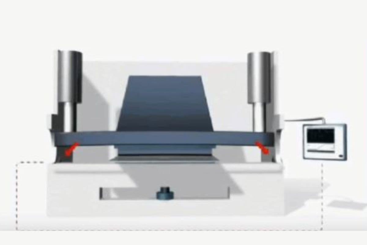
- Ease of Use and Openness of the CNC Controller: Controllers such as DELEM and Cybelec, featuring intuitive graphical interfaces and 3D touch operation, can cut programming time by more than 50%. Their openness also dictates future integration possibilities.
- Algorithm Maturity: A well‑developed algorithm can automatically calculate accurate compensation curves based on parameters such as material grade, thickness, tensile strength, and V‑die width. Advanced systems even possess self‑learning capabilities, dynamically adjusting the compensation model using feedback from previous bend angle measurements. This enables the system to handle variations between material batches and paves the way for true intelligent manufacturing.
- Value of Offline Programming Software: Robust offline programming solutions (e.g., Profile‑T3D) allow engineers to complete all programming, bend‑sequence optimization, and 3D interference simulation directly from an office workstation. Beyond identifying potential collision risks early, the real breakthrough is separating programming time from valuable machine runtime—achieving the ideal state where “the machine is always producing, while programming happens in the office.” This is the ultimate tool for boosting overall equipment effectiveness (OEE).
Ultimately, selecting a crowning compensation system is a delicate balance among precision, efficiency, and cost. By applying the above framework for systematic evaluation, you can cut through the complexity and make a decision that best aligns with your factory’s long‑term development strategy.
Ⅶ. Maintenance and Troubleshooting
7.1 Regular Inspection and Maintenance of Crowning Systems
Regular inspection of the crowning system is essential for maintaining its performance and extending the press brake's lifespan. Inspect key components such as wedges, hydraulic cylinders, and CNC controls for signs of wear, misalignment, or damage, and address any issues promptly to prevent further complications.
7.2 Calibration
Calibrating the crowning system ensures accurate and uniform bending results. This involves setting up the system based on the material's thickness, length, and type. For dynamic crowning systems, ensure that sensors and CNC controls are functioning correctly. Regular calibration helps maintain precision and reduces the risk of defects.
7.3 Lubrication
Regularly lubricate components like wedges, ball screws, guides, and bearings according to the manufacturer's schedule to reduce friction and wear. Proper lubrication ensures smooth operation and prevents premature wear and tear.
7.4 Hydraulic System Maintenance
For press brakes with hydraulic components, check for fluid leaks, ensure the fluid level is correct, and inspect hoses and seals for damage. Regular maintenance helps prevent failures and ensures consistent performance.
7.5 Backgauge and Crowning System
Ensure the backgauge system is well-calibrated and free from debris. Regularly check and adjust the crowning system for uniform bending along the entire sheet length. This contributes to accurate and consistent bends.
7.6 Troubleshooting Common Issues
Uneven Bends
Uneven bends often result from beam deflection during the bending process. Proper crowning adjustments ensure even pressure distribution. If uneven bends persist, inspect the system for debris or misalignment and make necessary adjustments.
Manual vs. Dynamic Crowning
Manual crowning systems can be time-consuming and prone to error, leading to increased scrap rates. Dynamic crowning systems provide precise, automated control, enhancing bending accuracy and reducing operator intervention.
Adjusting Crowning Systems
For manual crowning systems, make incremental adjustments to the wedges. Measure the bend angles at the ends and middle of the workpiece, and adjust the wedges until the desired accuracy is achieved. Regular fine-tuning of the crowning system ensures precise and uniform bends.
Ⅷ. FAQs
1. How does crowning affect the bending process in a press brake?
Crowning helps to adjust the bending force distribution along the press brake, minimizing deformation. As a result, it ensures the produced bends are consistent and precise by counteracting the ram and bed deflections during the bending operation.
2. How do press brake crowning systems ensure bending accuracy?
Crowning systems ensure accuracy by equalizing pressure across the bending length. This balance prevents distortion and consistently produces accurate bends, especially in long workpieces, by addressing the flexing that occurs naturally during the bending process.
3. What safety regulations pertain to the operation of press brakes with crowning systems?
Safety regulations may encompass proper training, regular equipment maintenance, and use of protective measures to prevent accidents. Operators must follow guidelines for setup and operation, ensuring that crowning adjustments do not compromise machine safety or lead to equipment failure.
4. In what ways does crowning contrast with other press brake adjustment techniques?
Crowning specifically addresses flexing issues in press brakes, setting it apart from other techniques like die shimming or adjusting ram position. It directly targets the even distribution of bending force, which is critical for maintaining high precision in long bending operations.
Ⅸ. Conclusion
In a nutshell, press brake crowning plays a pivotal role in press brake manufacturing. By setting reasonable bending compensation parameters, the spring back of the bending workpiece can be effectively reduced, improving the bending accuracy while ensuring product quality.
With the rapid development of technology, technologies like advanced sensors, data analysis, and machine learning will be applied to press brake crowning, achieving instant, dynamic, and adaptable crowning control and further enhancing press brake processing accuracy and efficiency.
In this era of rapid technological development, it is important to choose an experienced and advanced press brake manufacturer.
ADH Machine Tool, a professional press brake manufacturer for over 40 years, not only offers high-quality CNC press brakes but is also dedicated to innovation and research to meet the changing requirements of the market. To see the full specifications of our innovative machines, we invite you to download our latest brochures.
If you have questions or want to discuss how our advanced crowning technology can benefit your operations, please contact us. Our team of experts is ready to help you find the perfect solution.