I. Redefining the Question: From "Can it be done?" to "How should it be done?"
The question seems simple: Can you bend a box with a press brake? While the immediate answer is "yes," anyone who has watched a finished flange collide with the machine's ram knows the true challenge lies not in if, but how. This frustrating reality turns a single question into many: How do you manage interference? What is the correct bend sequence? Which tools are essential?
This guide provides the definitive answer. We will deconstruct the entire process, moving beyond trial-and-error to establish a repeatable science. From spatial strategy and tooling to advanced compensation and smart investment, what follows is your complete playbook for mastering the box bend and unlocking new levels of precision and profit.
1.1 Clarifying the Answer: Yes—but it’s ultimately a battle of geometry and space
The answer is yes: with a press brake, you can absolutely form box-like structures with multiple vertical sides.
But this is not a simple yes-or-no issue. It’s a precise game of geometry and spatial planning. What you’re really facing is not the machine’s mechanical limit, but the limits imposed by physical space.
The key challenge is interference—collisions between the already formed sidewalls (flanges) of the part and the press brake components (punch, die, or frame) during subsequent bends. Success depends on your ability to anticipate, avoid, or cleverly overcome these constraints through strategic tool use.
Thus, the question should not be “Can it be done?” but “Given my current equipment and tooling, how can I design the bending sequence and choose my tools to win this spatial game?”
1.2 The Core Challenge: Understanding and Visualizing Sidewall Interference
Sidewall interference is the root cause behind nearly every failed box bend. To truly master it, you must be able to mentally visualize two typical failure scenarios:
- Scenario A: The “head-on collision” during upward bending
- Process: Picture yourself trying to finish the final bend on a U-shaped channel or box.
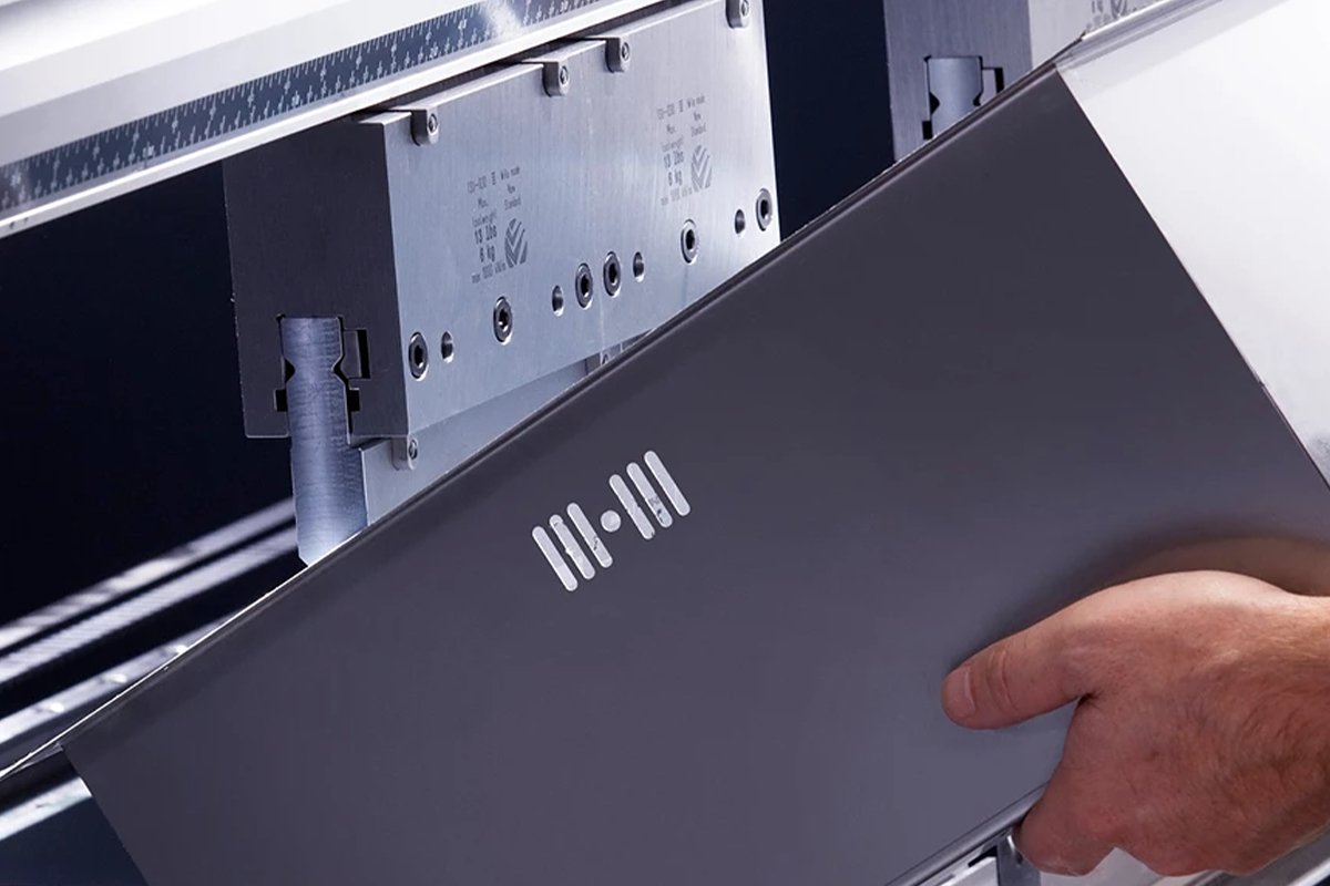
- Visualization: As the punch moves downward into the V-die, the free end of the sheet is pushed upward, forming a 90-degree angle. During this motion, an already-formed vertical flange on the opposite side acts like a wall, slamming into the punch holder—or even the machine’s upper beam. The taller the sidewall and the sharper the bend, the earlier this collision occurs, ultimately making the bend impossible or ruining the part.
Figure 1: During upward bending, the existing sidewall (shown in red) collides with the standard straight punch.
- Scenario B: The “bottoming out” conflict during downward bending
- Process: This occurs when forming Z-shapes or bending flanged parts downward.
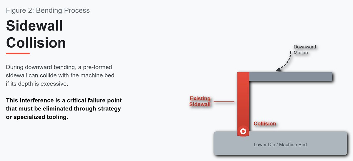
- Visualization: As the punch descends, the already-formed downward flange follows the sheet and moves toward the lower die. If the flange depth exceeds the safe clearance between the die edges and the machine bed, it will impact the die’s sides or the bed surface—causing jams, incomplete angles, or part deformation.
Figure 2: During downward bending, the existing sidewall (red) collides with the lower die or machine bed when its depth is excessive.
Understanding these two scenarios is the foundation for solving interference problems. Every complex box-bending challenge can be traced to variations or combinations of these two fundamental cases. The following sections—focused on bending sequence strategy and specialized tool selection—exist solely to eliminate these fatal collisions.
1.3 Strategic Decision: Press Brake vs. Box and Pan Brake
Before investing time and money to solve interference issues on a press brake, a crucial strategic decision awaits: are you using the right machine? For box-type bending, the market offers a specialized alternative—the Box and Pan Brake.
The Box and Pan Brake—also known as a Finger Brake—was designed specifically to eliminate sidewall interference. Its clamping beam is segmented into removable “fingers” of various widths. During box forming, the operator simply removes the fingers that would interfere with the sidewalls, thus creating physical clearance for the part.
In contrast, the Press Brake is a universal platform. Its standard straight punch cannot directly handle box formations, but it offers unmatched power, precision, and flexibility. By investing in specialized tooling, a press brake can overcome virtually any interference challenge, handling thicker materials and more complex geometries.
| Feature | Box and Pan Brake | Press Brake |
|---|---|---|
| Core Principle | Creates clearance by physically removing obstructions (removable fingers). | Avoids interference by changing tool geometry (e.g., gooseneck punch). |
| Design Purpose | Tailored for forming boxes, trays, and enclosed four-sided parts. | Designed for all sheet metal forming tasks—broader functionality and greater force. |
| Typical Applications | Standard boxes, shallow trays, adjacent bends; ideal for prototyping and small batches. | Complex geometries, high precision, thick materials, large-scale automated production. |
| Advantages | Intuitive setup, straightforward operation—the most direct and low-cost solution for common box interference problems. | Extreme precision, high tonnage, programmable CNC capability; tool changes enable infinite geometric possibilities. |
| Limitations | - Restricted by material thickness and length. - Lower accuracy and repeatability than CNC presses. - Difficult to handle complex angles or radii. | - Standard tooling cannot form boxes directly. - Specialized dies are expensive. - Requires advanced programming and setup know‑how. |
| Summary | “The master of spatial clearance”: it removes whatever stands in the way. | “The master of geometric design”: it bends cleverly around the obstacles. |
Decision Guidelines:
- If your main work involves small batches of standard-sized metal boxes, enclosures, or trays (typically sheet thickness <3 mm), then a Box and Pan Brake offers the highest return on investment for your shop.
- If your operations require high-volume production, or involve thick materials (>3 mm), irregular shapes, and demanding precision, then investing in a CNC-equipped Press Brake with a versatile tooling library is the only path to truly professional, efficient manufacturing. It transforms interference problems from a question of “Can it be done?” into “How can it be done faster, more accurately, and more elegantly?”—an art of engineering perfection.
II. Building the Foundation for Success: The Two Pillars of Box Bending Mastery
Once you grasp the essence of interference, you move beyond uncertainty about whether a box can be formed and enter the domain of how to form it perfectly. In this spatial and geometric contest, victory relies not on a single trick but on two essential pillars: an intelligent tool arsenal and a carefully engineered bending sequence strategy. Neglecting either will lead to costly failure.
2.1 Pillar One: Sharpen Your Weapons—Building a Strategic Tool Library
When it comes to box-style bending, the goal isn’t to hunt for a single “best tool,” but rather to build a strategic tool library capable of tackling all forms of interference challenges. Every choice should serve one core purpose: creating sufficient physical clearance for the preformed sidewalls. For more reference on tooling setups and press brake configurations, explore the resources available at ADH Machine Tool.
Upper Tool (Punch): The Art of Height, Shape, and Configuration
The upper punch is your primary weapon for breaking through the interference barrier. A well-equipped professional tooling library should include the following strategic configurations:
- Height Determines Success: This is a basic yet often overlooked parameter. When forming the third and fourth sides of a box, the upward-bent walls require sufficient vertical clearance to prevent catastrophic collisions with the press brake’s top beam (Ram). The following field-proven formula helps you accurately calculate the minimum punch height (H) needed:
H ≥ (D / sin(45°)) + (R / 2) ≈ 1.414D + 0.5R Where: D = box depth, R = upper beam thickness
This formula is derived from the geometric relationships between the workpiece, tooling, and machine at the end of a bend, ensuring sufficient clearance along the most critical diagonal. Investing in taller punches is, therefore, the most direct way to expand your bending capabilities. You can learn more about practical applications and how to bend a box with a press brake using these principles.
- Gooseneck Punch: This classic tool is indispensable for U-shaped and box-type parts. Its deeply recessed neck provides valuable clearance for upward-flanged walls. However, note that because its force line isn’t perfectly vertical, the gooseneck punch generally offers less structural strength and rigidity than a straight punch of similar size. Excessive load can lead to deformation or even tool failure.
- Segmented Tooling: This is the “magic cube” for tackling localized interference. By breaking a full-length punch into sections of varying lengths, you can remove individual segments precisely where interference occurs, creating a “window” through which protruding features—such as tabs or adjacent preformed sides—can pass freely. It’s an essential solution for complex box geometries.
- Advanced Shaped Punches:
- Acute/Offset Punches: When bends sharper than 90° or Z-shaped formations are required, these punches—with their sharp angles and offset geometry—can reach into tight spaces and perform tasks impossible with standard tools.
- Hemming Tools with Swing Ears: In high-end applications, these advanced punches feature movable side wings that automatically swing outward after bending, allowing even fully closed box parts to be easily removed. This dramatically boosts productivity and final product yield.
Lower Tool (Die): Opening Width, Angle, and Surface Protection
Selecting the right lower die is just as critical—it dictates the bend radius, required tonnage, and final part quality.
- The “8× Rule” for V-Openings: This is one of sheet metal’s golden rules—the V-opening width should be approximately eight times the material thickness.
- When to Follow It: For mild steel with a tensile strength around 400 MPa, this rule produces an inner bend radius roughly equal to the material thickness (R ≈ T). It’s an ideal starting point, balancing forming force with bending precision.
- When to Break It:
- Harder Materials (e.g., stainless steel): Require greater force; a wider V-opening (10–12× thickness) helps reduce tonnage and prevents outer surface cracking.
- Softer Materials (e.g., aluminum): Need less force; a narrower V-opening (around 6× thickness) yields a tighter bend radius.
- Specific Radius Requirements: If the drawing calls for a large bend radius, choose a wider V-opening. For a smaller radius, use a narrower one—within the material’s forming limits.
- Non-Marking Dies: When working with surface-sensitive materials such as aluminum, mirror-finish stainless steel, or pre-coated sheets, standard steel V-dies can leave visible pressure lines. Using dies fitted with polyurethane inserts or rotating ball bearings eliminates these marks, cutting out costly post-polishing while maintaining the product’s visual quality.
2.2 Pillar Two: Mastery in Motion — The Golden Rules of Bend Sequencing
If tooling is your hardware, bend sequencing is the critical “software algorithm” that determines success or failure. A poor sequence can easily lead you into a “dead end,” with the part trapped by its own geometry. While modern CNC press brakes can simulate collisions and recommend optimal sequences automatically, understanding the logic behind them remains the hallmark distinguishing a skilled technician from a true master.
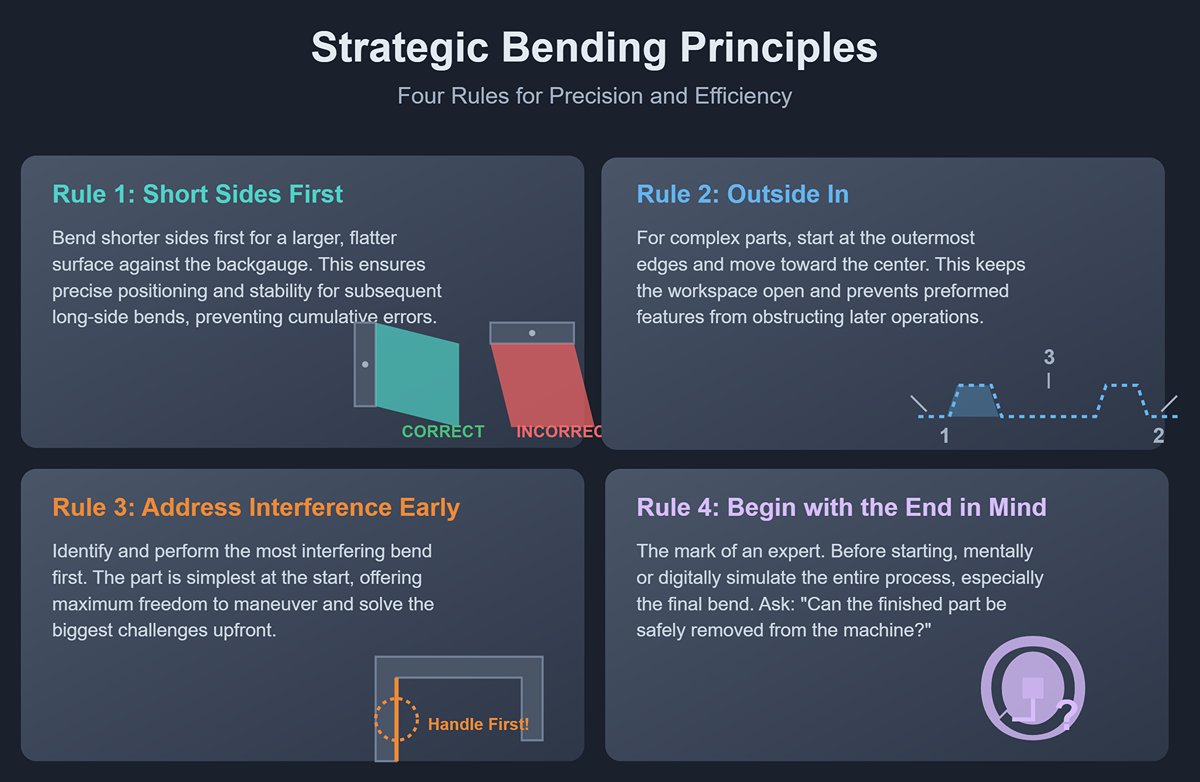
When planning the bend sequence for box parts, follow these four golden rules:
- Rule One: Short Sides First, Long Sides Last — This is the most fundamental principle. Bending the shorter sides first ensures that when tackling the longer sides later, the part can rest against the backgauge (Backgauge) with a larger, flatter surface for precise positioning. In contrast, if you bend the long sides first, the part becomes narrow and unstable, making accurate gauging difficult and introducing cumulative errors.
- Rule Two: Work from Outside In, from Far to Near — For complex parts with multiple bends, begin at the outermost edges and gradually move toward the center. This approach keeps the machine’s workspace as open as possible throughout the process, preventing preformed features from obstructing subsequent operations.
- Rule Three: Tackle Easy Bends First, Address Major Interference Early — Identify interference-prone bends early. Handle them first or design a dedicated solution. You can compare techniques like press brake vs. pan brake by visiting bend a box with a press brake.
- Rule Four: Begin with the End in Mind — Simulate Removal — This is the highest level of strategic thinking, marking the true experts. Before starting any operation, mentally—or digitally—simulate the final bend and ask one crucial question:
Once the last corner is formed, can the closed box be safely removed from the punch?
This question is often neglected. After the final bend, will the fully enclosed box be trapped within the punch? This is especially critical for parts with inward return flanges—always ensure sufficient height and clearance for the part to rotate or tilt its way out.
This reverse-engineering mindset allows you to foresee and avoid potential dead ends right from the first step. For additional visual guidance on complex bending paths and collision avoidance, see examples at bend a box with a press brake.
With strategic tool combinations and mastery of the golden bend sequencing rules, box bending transforms from a game of chance into a precise and controlled art of engineering.
III. Master Blueprint: A Step-by-Step Guide to Perfecting the Standard Four-Sided Box
Transforming a flat sheet of metal into a precise four-sided box is not a matter of simply making a few bends—it’s a choreographed process that blends calculation, strategy, and skilled craftsmanship. Think of it as a well-rehearsed ballet: every move must be executed with precision to produce a flawless final form. The following step-by-step guide takes you from concept to reality, guiding you through every critical stage on the journey from blueprint to a meticulously formed product.
3.1 Step 0: Precise Planning—It All Begins with Design and Calculation
Before you ever touch the cold steel sheet, the real work begins at the drawing board and calculator. We call this the “zero step” because it forms the foundation on which everything else depends. A single planning error can render all subsequent hours of labor and costly materials worthless.
- Core Task 1: Master the Material’s Physical Behavior—Bend Compensation When metal bends, the outer fibers stretch, the inner fibers compress, and only a layer between them—the “neutral axis”—retains its original length. To achieve accurate final dimensions, you must calculate and compensate for this deformation. Two key parameters define this process: the K-Factor and the Bend Deduction (BD).
- A Priceless Secret: Stop relying on generic K-factor charts from the internet! The best shops never do. Even slight variations in material batch, tooling wear, or machine characteristics can skew theoretical values. The most reliable approach is always an actual bending trial:
- Take a piece identical to your workpiece in material, thickness, and rolling direction.
- Using the same punch and die set intended for production, bend a standard 90° angle.
- Measure the actual leg lengths of the bend precisely with calipers or an angle gauge.
- Use these real measurements to back-calculate the true bend deduction for your current setup.
This value becomes the golden standard for all subsequent calculations—the lifeline of your product’s dimensional accuracy.
- Core Task 2: Design for Stress Relief—Incorporating Bend Reliefs At the corners of a box, where two bend lines intersect, material stress peaks. Without proper relief, the metal will compress and jam, causing tearing, wrinkling, or bulging—all hallmarks of poor craftsmanship. By cutting a small notch (a bend relief) at each intersection in the flat pattern, you create a safe pathway for those otherwise destructive stresses.
- Professional Design Guideline: An effective relief slot should be at least as deep as the bend radius plus material thickness, and its width no less than the thickness—ideally 1.5 times that. This ensures adequate clearance during bending, resulting in clean, crisp corners.
3.2 Steps 1 & 2: Establishing the Foundation—Forming the First Two Opposing Sides
Following the golden rule established earlier—bend the short sides first, then the long sides—we begin shaping the box’s basic structure. The goal here is to create two perfectly parallel and accurately angled walls. These will serve as your reference foundation for all subsequent operations, much like a building’s foundation determines the integrity of everything above it.
- Precise Alignment: Place the unfolded blank on the press brake, and align the first bend line exactly with the punch’s center using back gauges or scribed marks. Ensure the workpiece is flat and firmly seated against the backstop.
- Execute the Bend: Activate the machine to form a clean 90° bend. On a CNC brake, the angle is controlled by the program; in manual operation, confirm with an angle gauge until the desired angle is achieved.
- Create Symmetry: Release the workpiece, rotate it 180°, and repeat the process on the opposite short edge.
After these two steps, you’ll have a U-shaped piece. You can apply the principles demonstrated in bend a box with a press brake to improve bending consistency and precision. Interference is rarely an issue at this stage, making the process relatively smooth. Still, take great care to ensure both sides are perfectly parallel and vertical—any slight error now will snowball in later steps.
3.3 Steps 3 & 4: The Critical Challenge—Forming the Final Two Interfering Sides
This is the make-or-break stage—the line separating novices from experts. Here you’ll face the main technical obstacle: sidewall interference. The choices you make in tools and technique will directly determine your success.
Strategic Tool Setup:
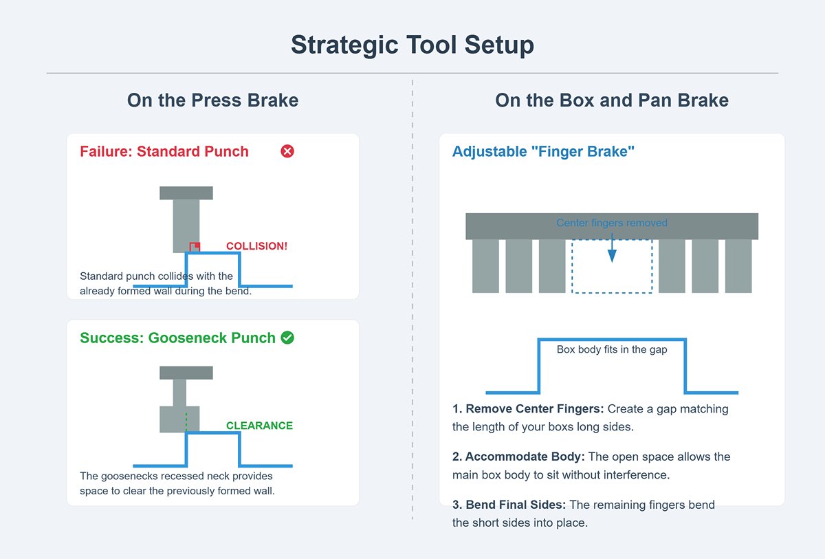
- On the Press Brake: Switch to a gooseneck punch, whose distinctive recessed neck is purpose-built to clear already formed walls. If you persist with a standard straight punch, the upright sides will collide with the ram or crossbeam during bending, guaranteeing failure.
- On the Box and Pan Brake: This is where the adjustable “finger brake” shines. Based on the length of your box’s long sides, remove the appropriate center fingers to create the necessary gap. The open space accommodates the box body, while the raised short sides slot neatly between the remaining fingers without interference.
Perform the Third Bend:
Place the U-shaped piece into the adjusted tooling, aligning the third bend line accurately. Proceed slowly, watching the gap between the preformed walls and the machine to ensure no collision occurs throughout the motion.
Conquer the Final Edge:
This last bend is the toughest—by now, three sides enclose the structure, leaving minimal working space. Carefully slide the piece into position and align the fourth bend line.
- A Little-Known Expert Tip: Before making the third and fourth bends, use hand pliers to slightly bend the corner tabs outward by about 1–2°. Though subtle, this pre-adjustment eases compression stress between the tabs and walls during the final closures, preventing wrinkling or distortion and ensuring tight, smooth corners with a refined finish.
Safe Removal:
After the final bend, your enclosed box is complete. Remove it carefully from the tooling. For deeper boxes or designs with inward return flanges, you may need to tilt or rotate the workpiece, using geometry to help it escape the upper die’s grip.
3.4 Step 5: Quality Assurance—From Forming to Perfection
A formed box doesn’t automatically qualify as a finished product. Rigorous quality inspection is the final—and most vital—defense line ensuring function, aesthetics, and durability. It’s what separates something that’s merely “done” from something truly “perfected.”
- Geometric Accuracy Check:
- Dimensions: Using calipers or a height gauge, measure the box’s final length, width, and height. Pay close attention to tolerance stack-up—even minor deviations at each bend can accumulate and push the final dimensions out of specification.
- Angle and Perpendicularity: Use a high-precision engineer’s square or a digital angle gauge to verify that every corner is exactly 90°. Also confirm that all four sidewalls stand perfectly perpendicular to the base.
- Surface and Structural Integrity Inspection:
- Die Marks: Examine the outer surface along each bend line for two parallel indentations, typically caused by the shoulders of the V-die. In applications with high cosmetic demands—such as stainless steel panels or aluminum enclosures—these marks are considered defects and may require a mark-free die or secondary finishing to eliminate.
- Cracking: Use a magnifier to carefully inspect the outer bend radius for fine cracks, especially when working with hard materials like stainless steel or high-strength aluminum alloys and using very tight bend radii. Cracks are clear warning signs of excessive stress.
- Burrs and Sharp Edges: With gloves on, run your hand along all cut edges to ensure they are smooth and burr-free. This prevents potential injury to users or damage to wiring during product use.
- Flatness Inspection: Place the box on an absolutely flat reference surface—such as a granite inspection plate—to verify that the bottom lies flat and that no warping has occurred due to uneven stress release in the material. Check as well that the four top edges align in the same plane.
IV. Advanced Arsenal: Mastering Complex Box Forms and Extreme Precision
Once you can craft a standard four-sided box with ease, you’ve earned entry into the deeper realm of sheet metal forming as a precision art. At this level, success no longer depends on rigid procedures but on a refined grasp of space, physics, and the strategic interplay of processes. It’s no longer mere operation—it’s strategic engineering.

4.1 Advanced Sequencing: Managing Asymmetric and Multisided Boxes
When faced with asymmetric, tapered, or multi-sided (five, six, or more panels) enclosures, the golden rule of “short sides first” loses its symmetry advantage. At that point, you need to shift to a higher-level, collision-prediction and spatial-logic mindset.
- Reverse Planning from the Dead End: This marks the key cognitive difference between top engineers and ordinary technicians. Instead of thinking step-by-step from the beginning, start mentally simulating the most constrained, interference-prone final few bends.
- Identify the Most Difficult Bend: Locate the bend that’s boxed in by three sides, includes an inward flange, or demands the most challenging angle—a true “bottleneck” step.
- Simulate the Escape Path: Visualize whether, after that hardest bend, the part can still be removed smoothly from the tooling. Will it become trapped by the upper die? During the bending motion, could any other section collide with the machine?
- Plan Earlier Steps Around the Escape: Only after confirming that the toughest bend is feasible should you plan the preceding steps. The entire sequence design is ultimately about creating a workable pathway for that final “dead-end” bend—an elegant exercise in reverse engineering.
- Asymmetric Structures: Anchoring on the Baseline: For asymmetric or tapered boxes, the absence of parallel edges makes stable positioning against the backgauge extremely challenging.
- A Lesser-Known Secret: Experts intentionally create a temporary reference edge. They select the longest, straightest edge as the absolute baseline for the entire fabrication process. Bends unrelated to this baseline—and that won’t cause interference—are completed first. Then this long edge becomes the stable reference for all subsequent complex or asymmetric bends. In extreme cases, engineers even design a sacrificial “process edge” in the flat pattern—an element cut away only before final delivery—that exists solely to provide a consistent, reliable datum throughout fabrication.
- Windowed and Segmented Bending: When a long edge includes multiple separate flanges rising like battlements, a standard long punch would collide with the flat areas between them. In such cases, the segmented punch shifts from an option to the only viable solution. By precisely assembling only the segments corresponding to the flange positions, you can complete several discontinuous bends in a single stroke. The “window” spaces between punch segments provide perfect clearance for previously bent or obstructing surfaces.
4.2 The Soul of Precision: Scientifically Compensating for Springback
Springback is the perpetual nemesis of sheet metal forming—the tendency of metal to partially return to its original shape after the bending force is released. Every pursuit of extreme accuracy is, in essence, a scientific battle against springback.
- Overbending: The most fundamental compensation method—bending slightly beyond the target angle (for example, bending to 88° for a 90° goal) so that it “springs” back into specification. The real mastery lies in knowing exactly how much to overbend. This depends on material type, thickness, bend radius, and V-die opening. Modern CNC press brakes, aided by built-in material databases and angle measurement systems (such as laser angle detectors), can automatically provide real-time feedback and compensation, achieving batch consistency that was once unthinkable.
- Coining: This is the most extreme precision technique—a brute-force approach. It applies enormous pressure (typically five to eight times that of air bending), forcing the punch tip deeply into the material and permanently altering the internal stress structure to achieve full plastic deformation.
- Effect: Nearly eliminates springback entirely, producing angles that perfectly match the dies and an extremely tight inner radius.
- Trade-offs: Requires extremely high tonnage, causes rapid die wear, and leaves permanent imprint marks on the part. Given today’s high-accuracy press brakes, this costly, tool-intensive method is now reserved mostly for specialized high-precision fields rather than general manufacturing.
- Bottoming: A hybrid between air bending and coining, where the punch tip lightly presses into the material surface but without the massive force used in coining. It offers greater accuracy and less springback than air bending, while requiring far less tonnage than coining—making it an ideal balance between precision and cost.
4.3 Expert Techniques: Unlocking High-Value Hybrid Processes
The finest sheet metal products are rarely the result of a single process. They are the culmination of multiple techniques, strategically combined to achieve perfection. Knowing when to go beyond bending itself marks the final threshold separating masters from mere craftsmen.
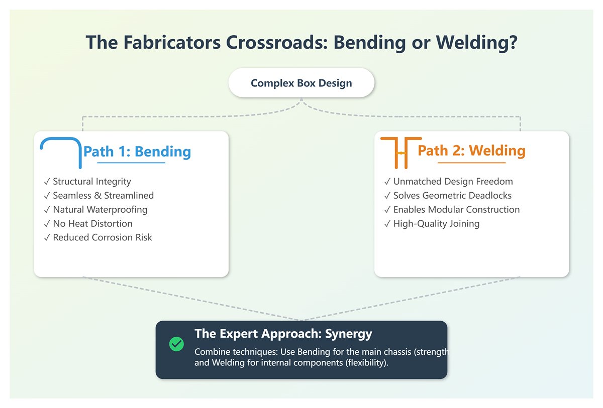
- Bending vs. Welding: The Eternal Contest When designing a complex box structure, one central decision always arises: which corners should be bent as a single piece, and which should be manufactured separately and then welded together?
- Advantages of Bending: A monolithic corner offers superior structural integrity, a seamless streamlined appearance, and a naturally waterproof and dustproof seal. It eliminates heat distortion from welding, saves time in grinding weld seams, and avoids potential long-term corrosion points.
- Advantages of Welding: Welding provides unparalleled design freedom. When a box’s geometry becomes so complex that any bending sequence leads to a mechanical deadlock, the only viable path is to split it into several simpler sections, bend each one separately, and then join them through high-quality welding—such as laser welding.
- Expert-Level Approach: Combine both techniques on a single product. For instance, the main chassis of a precision server enclosure might use integral bending to ensure structural strength and electromagnetic shielding integrity, while internal brackets or removable partitions are added through spot welding or screw assembly to maintain flexibility and serviceability.
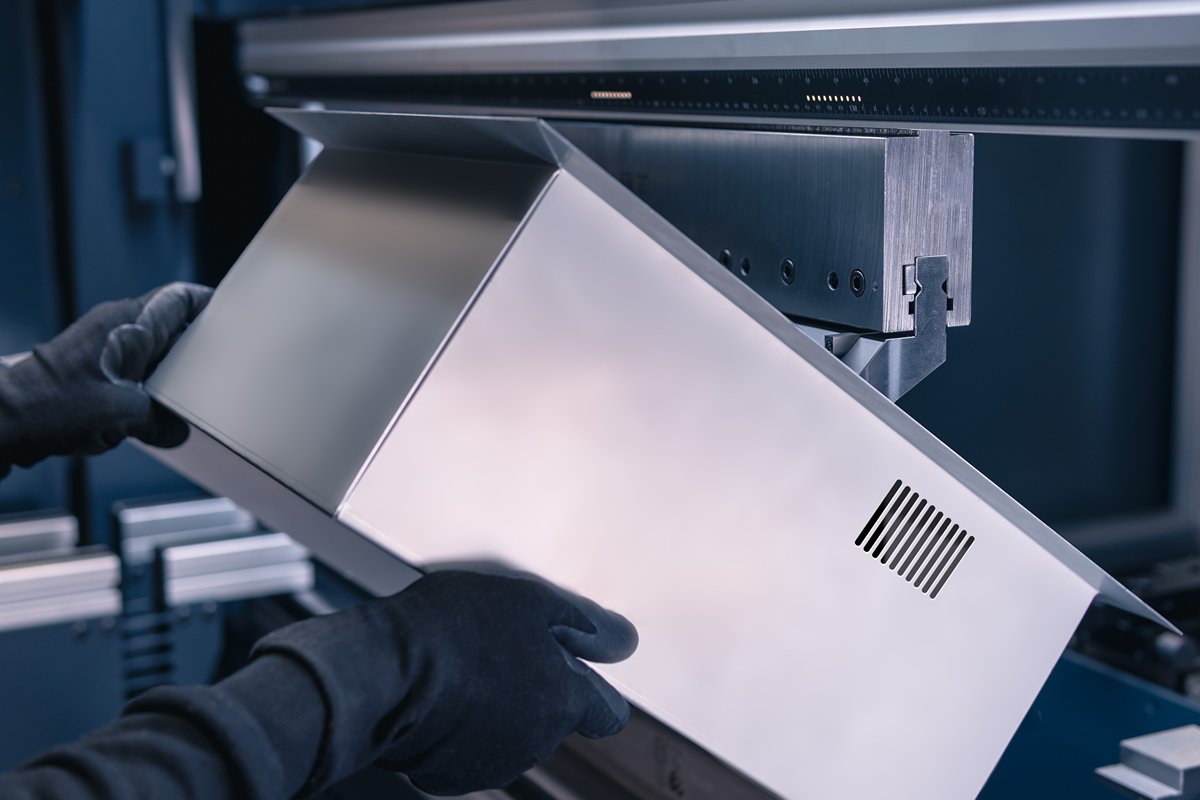
- Bending + Stamping/Drawing For complex enclosures that require sidewall features such as reinforcing ribs, louvers, cooling slots, or embossed bosses, bending alone cannot create these 3D details. The correct industrial workflow should be:
- In the flat, unfolded state of the sheet, use a punch press or hydraulic press to pre-form all the 3D features.
- Then feed this pre-shaped flat sheet into the press brake for bending and final forming.
This demands advanced sheet metal design software at the engineering stage to precisely calculate how these features will shift or distort during bending. It ensures they do not end up in stress concentration zones along bend radii, which could otherwise cause tearing or deformation.
By mastering these advanced strategies, you transcend the role of a mere machine operator following instructions. You become a creative problem solver—an artisan engineer who injects structural intelligence and aesthetic value into every product. Your mindset evolves from “how to make it” to “how to make it better.”
V. Strategic Investment: Selecting and Optimizing Equipment for Box Bending
Elevating from the technical question of “how to operate” to the strategic one of “how to equip” marks a decisive step toward a company’s leap in capability. In the precise world of sheet metal fabrication, machines are far more than cold steel—they embody the factory’s technical ambition, efficiency ceiling, and profit potential. For the specialized yet crucial domain of box bending, choosing the right equipment is equivalent to installing a high-powered engine for your enterprise. This guide, viewed through the lens of operators, buyers, and decision-makers alike, helps you evaluate, optimize, and redefine your equipment strategy.
5.1 Operator Self-Inspection Checklist: Is Your Press Brake Ready for Box Work?
Not all press brakes are created equal. Before you commit your time and costly materials to a complex box bending project, use this checklist to run a quick “combat readiness” diagnostic on the machine you work with every day. Every “no” could signal a crippling bottleneck in efficiency, accuracy, or safety.
| Inspection Item | Key Question | Why It’s Crucial for Box Bending |
|---|---|---|
| 1. Open Height & Stroke | Does my machine have enough open height and stroke to accommodate the diagonal dimension of a deep box? | This is a strict physical limitation. When bending the third or fourth sides, the upward-folded walls must have a diagonal length smaller than the machine’s open height; otherwise, catastrophic collision occurs. Insufficient stroke means the punch can’t descend deeply enough to complete the bend—an absolute ceiling on capability. |
| 2. Ram Geometry | Is the upper beam (ram) slim enough, or is it bulky with protrusions? | A common “hidden killer.” Even with adequate open height, a heavy ram can severely restrict clearance, causing unexpected interference. In practice, technicians sometimes remove decorative covers from older machines just to gain those critical few millimeters of space. |
| 3. Tooling System Compatibility | Does my machine use a standard tooling system (such as WILA/Trumpf or American style)? Is segmented tooling easy to replace and configure? | The soul of box bending lies in flexible use of dedicated and sectional tools. Nonstandard or outdated systems lock you into a narrow, expensive supplier base—effectively crippling flexibility and competitiveness. |
| 4. Backgauge Axes | Is my backgauge limited to a basic X-axis, or does it include R-axis (vertical movement) and Z-axis (independent horizontal movement)? | Simple backgauges are helpless when dealing with tapered or asymmetrical boxes. A true multi-axis backgauge (4 or 6 axes) allows fingers to follow complex contours intelligently—a leap from “can only make square boxes” to “can make any box.” |
| 5. Control System (CNC) Capability | Does the control system support graphical programming and 3D bend simulation? Can it automatically calculate bend sequences and detect collisions? | Modern CNC systems serve as both “brains” and “command center” for box bending. They simulate the bending process on-screen, identify all potential collisions in advance, and optimize the entire sequence. Without it, shops rely solely on veteran intuition and costly trial and error. |
| 6. Tool Clamping Mechanism | Is my machine equipped with quick-change clamping (hydraulic/pneumatic), or manual bolt-on assemblies? | Box bending requires frequent tool changes or adjustments. Manual clamping not only wastes time—often over 70% of setup—but also poses safety risks. One-touch hydraulic or pneumatic systems can cut tool changeover from a painful half-hour to mere minutes—the lifeline for small-batch, high-mix production. |
Diagnostic Conclusion: If your machine scores poorly on several of these factors, you’re essentially attempting to fight a modern precision war armed with “a rifle and a handful of bullets.” The outcome is inevitable—low efficiency, high cost, and disqualification from the most profitable, high-value contracts before the competition even begins.
5.2 Buyer’s Decision Guide: How to Invest in a Box-Bending Powerhouse
Purchasing a new machine is a cornerstone investment in your company’s competitiveness for years, even decades, to come. The following guide helps you look beyond simple comparisons of tonnage and length, and think like a true strategist—ensuring every dollar you spend becomes a blade sharpened for future growth.
Core Principle: Invest in Precision, Not Brute Force
In the world of modern precision sheet metal fabrication, a paradigm-shifting consensus has emerged: accuracy always outweighs tonnage. Rather than purchasing a massive, low-precision mechanical press brake and relying on the brute-force method of coining to hammer in angles, invest instead in a high-precision servo-electric or hybrid press brake that uses air bending to control springback with elegance and precision. Air bending requires far less tonnage, offers superior tooling versatility, and inflicts minimal wear on both the machine and the tooling. It’s a triumph of intelligence and efficiency.
Strategic Interpretation of Key Parameters
| Key Parameter | Traditional View (Cost-Oriented) | Strategic View (Box Bending-Oriented) |
|---|---|---|
| Machine Type | Hydraulic models are most common and moderately priced. | Servo-electric/hybrid machines deliver unmatched angular repeatability (up to ±0.003mm), essential for scientifically compensating springback. They’re also more energy-efficient, faster in response, and cheaper to maintain—a clear investment in the future. |
| Daylight (Open Height) | “Sufficient” is enough. | Make it as large as possible. This hard limit defines the maximum box depth you can produce. What seems “enough” today will become tomorrow’s bottleneck. Always reserve strategic capacity for deeper, more complex orders to come. |
| Stroke | As long as it can bend, it’s fine. | The longer, the better. A long stroke combined with generous daylight allows for tall gooseneck punches and extension modules, creating near-infinite geometric options for interference-free bending—your ultimate guarantee of process flexibility. |
| CNC Controller | Basic programming capability suffices. | Must offer 3D graphical display and offline programming tools. This empowers engineers to plan complex sequences and collision detection comfortably in the office, leaving the machine to execute flawlessly—key to maximizing Overall Equipment Effectiveness (OEE). |
| Backgauge System | Two or four axes are adequate. | A six-axis system (X–R–Z1–Z2–X–delta) or even more is ideal. It grants full positional freedom for any asymmetrical or tapered part—your golden ticket to handling high-margin, high-difficulty jobs. |
Recalculating Return on Investment (ROI)
A top-tier press brake comes with a premium price tag, but its returns are exponential. When calculating ROI, look beyond the initial purchase cost:
Strategic ROI = (Defect rate reduction from precision + Labor savings from automation + Profit growth from high-value contracts) − Initial investment
- Efficiency Revolution: Quick tool change, offline programming, and faster bending speeds can reduce non-productive setup time by over 80%, converting lost hours directly into usable capacity.
- Quality Breakthrough: The first-piece success rate rises from a luck-driven 50% to a predictable 99%, meaning less material waste, lower rework costs, and fewer customer complaints.
- Market Transformation: With the ability to handle complex box geometries, you can escape the low-margin red ocean of simple parts and enter a high-value blue ocean—transitioning from a price taker to a creator of value.
5.3 Three Common Costly Mistakes and How to Avoid Them
Countless factories have made expensive missteps in equipment investment, usually stemming from deeply ingrained misconceptions. Avoid these three major cognitive traps at all costs.
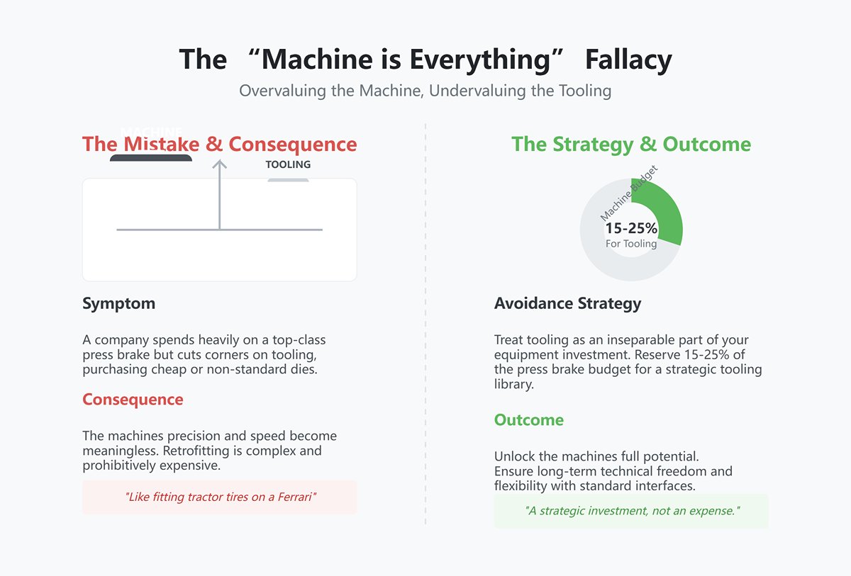
- Mistake 1: Overvaluing the Machine, Undervaluing the Tooling (The “Machine is Everything” Fallacy)
- Symptom: A company spends heavily on a top-class press brake but cuts corners on tooling—purchasing cheap, non-standard dies or neglecting essential gooseneck punches and segmented tool sets for box forming.
- Consequence: Like fitting tractor tires on a Ferrari—brutally limiting its potential. The machine’s precision and speed become meaningless. When the problem finally surfaces, retrofitting compatible tools proves complex, limited in choice, and prohibitively expensive.
- Avoidance Strategy: Treat tooling as an inseparable part of your equipment investment. Mandate that 15–25% of your press brake budget be reserved for an initial strategic tooling library, and commit to purchasing tools with international standard interfaces—it’s essential for long-term technical freedom.
- Mistake 2: Confusing Specifications with Geometry (The “Specification vs. Geometry” Trap)
- Symptom: Assuming a machine can bend deep boxes simply because the datasheet lists impressive daylight and stroke numbers.
- Consequence: Upon installation, you discover with dismay that despite large nominal dimensions, the upper beam or clamping system collides with the workpiece sidewalls during actual bending. The result: a machine that looks capable but is practically unusable.
- Avoidance Strategy: Replace assumptions with verification: bring your sample parts or drawings for live trials. If that’s impossible, insist the supplier provide detailed geometric dimensions of the upper tool mounting zone. Your engineers can perform interference simulations in CAD. Always remember—you’re buying usable clearance, not spec sheet numbers.
- Mistake 3: Worshipping Tonnage, Ignoring Technique (The “Tonnage Solves All” Myth)
- Symptom: Believing that increasing tonnage alone can solve all angular and springback issues through high-pressure coining.
- Consequence: A dangerously outdated and costly mindset. Coining demands five to eight times more tonnage than air bending—wasting enormous energy, accelerating wear on machines and tooling, and dramatically shortening their lifespan. Worst of all, it halts technical advancement by discouraging exploration of material behavior and springback compensation science.
- Avoidance Strategy: Fully embrace modern high-precision air bending technology. Invest in CNC servo press brakes with real-time angle measurement and automatic compensation features. Learn to manage springback scientifically, not suppress it with brute force. This is the only sustainable path to high-precision, low-cost, long-term production.
VI. Conclusion
6.1 Core Principles Revisited
We began by asking if a press brake can bend a box, and we've discovered the answer lies in how. Successful box bending is not a single action but a systematic process of managing spatial geometry, deploying strategic tooling, and executing a flawless bend sequence. It demands that we understand interference, apply the golden rules of process, and scientifically compensate for material properties.
6.2 Your Next Move: Turn Knowledge into Profit
Theory is only valuable when put into practice. Whether you're troubleshooting a difficult part or planning a strategic equipment upgrade, now is the time to turn your challenges into opportunities. For a comprehensive overview of our machinery and their capabilities, you can explore our detailed Brochures.
Don't let the next complex box bend be a problem—make it your advantage. Contact us today. Our team of experts is ready to provide a complimentary process evaluation, helping you transform cutting-edge theory into tangible, profitable results.


