Can you form UHMW in a press brake? The answer is yes, but only by fundamentally changing your approach. Standard metal-bending techniques will fail, resulting in cracked parts and inconsistent angles.
UHMW's unique molecular structure and thermal properties demand a specialized process of controlled heating, custom tooling, and managed cooling. This comprehensive guide moves beyond theory to deliver a practical, step-by-step methodology for mastering this challenging but achievable fabrication technique.
I. Straight to the Core: Press Brake Forming UHMW — Feasible, but Under Strict Conditions
1.1 The Short Answer: Yes — But Only If You Abandon the Metalworking Mindset
Yes, forming ultra-high-molecular-weight polyethylene (UHMW) with a press brake is entirely possible. However, treating it like bending a piece of sheet metal is almost a guarantee of failure. Success depends on completely unlearning everything you know about cold bending metals and embracing a process philosophy closer to "thermoplastic guidance" rather than brute-force deformation.
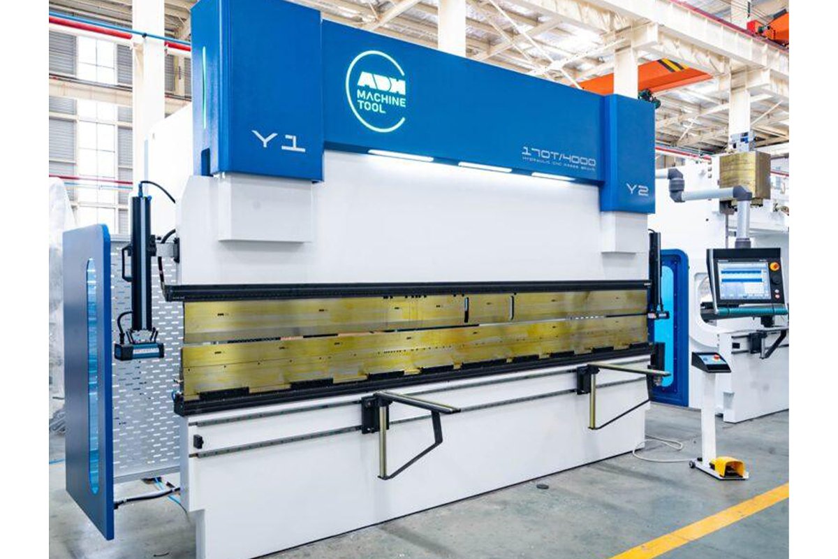
To better understand the specialized equipment and process adjustments needed, explore comprehensive guides on how to form UHMW in a press brake provided by ADH Machine Tool.
The fundamental differences between metals and UHMW dictate a completely different forming strategy:
- The Role of Heat Is Reversed: In metal forming, heat is an optional aid for special cases. For UHMW, heat is an absolute prerequisite. Any attempt to bend UHMW at room temperature will almost certainly cause cracking on the outer radius due to stress concentration.
- “Persuasion,” Not “Force”: Steel is rigid, so we overpower it until it yields permanently. UHMW is the opposite—flexible yet tough. You must gently heat it into a compliant state, then use tooling to persuade and guide it into its new shape.
- Extreme Thermal Expansion: UHMW expands roughly fifteen times more than steel when heated. From room temperature to 140°C, a one‑meter sheet can lengthen by about 2.5 mm. Neglecting this factor is a silent culprit behind dimensional inaccuracies.
Therefore, consider your press brake merely an execution tool—the true heart of the process is closer to localized thermoforming. For those seeking detailed industrial data, ADH Machine Tool offers downloadable brochures covering advanced press brake systems.
1.2 The Core Challenge: Mastering UHMW’s “Elastic Memory” and Low Rigidity
Successfully bending UHMW means contending with two stubborn physical traits:
- Exceptional “Elastic Memory” (Springback): UHMW has an extraordinary tendency to return to its original flat shape once pressure is released—a phenomenon known as springback. Its recovery is far greater than that of any metal, making it the most underestimated problem in UHMW forming. The only effective countermeasure is over-bending—forming the part well past the target angle. For instance, achieving a perfect 90° bend may require bending it to 75° or less to allow for springback. The exact degree of over‑bending must be determined experimentally.
- Deformation Control Due to Low Rigidity: Unlike stiff metal sheets, UHMW behaves more like a tough, elastic dough under pressure—prone to buckling or twisting in unsupported regions. Heating improves its workability but further destabilizes its geometry. Any mismanaged temperature or support in the heat‑bend‑cool cycle can result in severe warping or internal stress, rendering the part unusable.
1.3 The Three Pillars of Success: Precise Temperature Control, Customized Tooling, and Process Discipline
Achieving consistent, high‑quality bends in UHMW isn’t a matter of luck—it depends on strict adherence to three technical foundations:
1. Precise Temperature Control: Execute Within the “Golden Window”
Temperature is the single most critical factor. UHMW has an extremely narrow optimal forming window.
- Ideal Temperature Range: Heat the bending zone evenly to 130 °C–150 °C (265 °F–302 °F). Below 130 °C, brittleness remains and cracking is likely; above 150 °C, the material begins to soften excessively or approach its melt point, causing surface damage, dimensional drift, and loss of mechanical strength.
- Uniform Heating Is Everything: Ensure heat is precisely and uniformly distributed along the entire bend line. Standard methods include hot‑air guns with diffusers, strip heaters, or industrial ovens. Uneven heating inevitably causes inconsistent bend angles and poor straightness. For details on heating systems and temperature control practices, see how experts form UHMW in a press brake with precision.
2. Customized Tooling: Replace Sharp Edges with Gentle Radii
Conventional metal V‑dies are the enemy of UHMW—their sharp edges create destructive stress concentrations.
- Generous Radii Are Essential: This is the most critical adaptation. Use punches and dies with broad, rounded radii. The larger the radius, the more evenly stress is distributed, making the stretch‑forming process smoother. As a rule of thumb, the punch radius should be at least two to three times the material thickness.
- Achieve “Mark‑Free” Bends: UHMW’s soft surface scratches or dents easily under metal tooling. To maintain pristine surface quality, consider the following professional techniques:
- Cover the lower die with a urethane pad, whose elasticity cushions pressure and protects the surface.
- Mirror‑polish all tooling surfaces that contact UHMW.
3. Process Control: Gentle, Slow, and Steady
Handling must be deliberate and measured—forget the high‑speed, high‑pressure instincts of metal fabrication.
- Low Speed and Pressure: The ram descent speed should be set extremely low, with pressure far below what a same‑thickness metal sheet would require. The entire motion should feel smooth and fluid, allowing the polymer chains time to realign.
- Hold and Cool: After reaching the pre‑calibrated over‑bend angle, maintain pressure (dwell) briefly to let the part take shape. Then, while still clamped, allow it to cool slowly and naturally in air. Any attempt at forced cooling (e.g., water quenching) will induce severe warping and internal stress.
1.4 Who This Guide Is For: Technicians, Process Engineers, and Product Designers

This guide is not theoretical speculation—it’s a practical framework designed for professionals on the manufacturing front line:
- Manufacturing Technicians and Operators: Apply the specified temperature ranges, tooling setups, and handling procedures directly to improve success rates and minimize material waste.
- Process Engineers: Use the principles and technical elements herein to develop standardized UHMW bending SOPs and establish data‑driven quality control criteria.
- Product Designers: Understand UHMW’s forming limitations early in the design phase—specify realistic bend radii and tolerance expectations to ensure your designs are truly manufacturable.
For further guidance, learn more about how professionals form UHMW in a press brake to achieve superior results.
II. Diving Deeper: Why Bending UHMW Is a Science of Its Own
Bending UHMW isn’t just swapping out materials—it’s entering an entirely different domain governed by molecular structure, thermodynamic behavior, and mechanical response. It requires engineers and technicians to rethink the material’s temperament from the ground up and adjust their methods accordingly. At its core, this “science” lies in recognizing and mastering the vast physical divide between UHMW and metal.
2.1 Material Characteristics: Understanding UHMW’s Personality
The extraordinary behavior of UHMW stems from its ultra-long molecular chains. Picture ordinary polyethylene (HDPE) as a bundle of short strings, while UHMW’s molecular chains resemble millions of exceptionally long fishing lines intricately entangled with one another.
This unique microscopic architecture endows the material with a set of seemingly contradictory yet profoundly influential macroscopic properties that govern its processing behavior:
- Exceptional Toughness and Wear Resistance: The tight entanglement of long molecular chains creates a robust energy-absorbing network. When subject to impact or friction, the energy disperses efficiently rather than concentrating at a single point. As a result, UHMW exhibits unmatched impact strength—even at low temperatures—and remarkable abrasion resistance, earning it the title “king of plastics.” However, during bending, this means you must effectively “persuade” an entire molecular network to realign, rather than simply breaking it.
- Semi-crystalline Structure and Flexible Rigidity: UHMW is a semi-crystalline polymer containing both ordered crystalline regions that provide strength and heat resistance, and amorphous regions that offer toughness and flexibility. This combination gives UHMW a distinctive “hard-yet-supple” tactile character—it possesses measurable hardness, yet also displays considerable elasticity under stress, unlike the rigidity typical of metals.
- Extremely Low Thermal Conductivity and High Thermal Expansion: UHMW is an excellent thermal insulator, with a thermal conductivity only about 1/120 that of steel. This means heat struggles to penetrate the material evenly, causing the surface to overheat while the core remains cool. At the same time, its coefficient of thermal expansion is roughly 15 times that of steel. Combined, these traits form a substantial processing trap: uneven heating can lead to crooked bends, while uneven cooling and aggressive shrinkage may cause warping and severe internal stresses.
- Strong Molecular Memory Effect: Its ultra-long, entwined molecular chains hold a powerful tendency to revert to their original state after being deformed. This underlies UHMW’s pronounced springback and stress-relaxation behavior. Unlike metals that readily yield, UHMW continues to resist the imposed shape until its internal stresses eventually find a new equilibrium.
2.2 Performance Comparison: Why UHMW Cannot Be Treated Like Steel or Aluminum
Putting UHMW side by side with metals such as A36 mild steel or 6061 aluminum alloy quickly exposes their entirely different forming logics. Metals deform through lattice slip and dislocation motion—the essence of plastic deformation—whereas UHMW’s forming process involves thermally unlocking and guiding the reconfiguration of its entangled molecular network, followed by controlled cooling to lock the shape in place.
The stark contrast in key properties explains why conventional metalworking assumptions must be completely discarded when dealing with UHMW:
| Property | UHMW (Ultra-High-Molecular-Weight Polyethylene) | A36 Mild Steel | 6061 Aluminum Alloy |
|---|---|---|---|
| Bending Mechanism | Molecular chain rearrangement, thermoplastic deformation | Lattice slip, plastic deformation | Lattice slip, plastic deformation |
| Forming Temperature | Must be heated to 130–150°C | Cold bending at room temperature | Cold bending at room temperature |
| Elastic Modulus (GPa) | ~0.8 (very low) | ~200 (high) | ~69 (moderately high) |
| Process Insight | Extremely low stiffness—easy to bend but very hard to retain shape | High stiffness—requires significant force to yield | Relatively stiff—forms easily |
| Thermal Expansion Coefficient (µm/m·K) | ~200 (very high) | ~12 (low) | ~24 (moderate) |
| Process Insight | Highly thermally unstable—dimensional control is extremely challenging | Excellent thermal stability and predictable dimensions | Good thermal stability |
| Thermal Conductivity (W/m·K) | ~0.41 (very low) | ~50 (average) | ~170 (high) |
| Process Insight | Excellent insulator—uneven heating and cooling | Moderate conductivity—heat treatment is feasible | High conductivity—uniform heat distribution |
| Springback | Extreme and time-dependent | Present but predictable and stable | Noticeable, more pronounced than steel |
| Surface Hardness | Low—easily scratched or indented | High—resistant to damage | Moderate—somewhat scratch-prone |
This table makes one thing unmistakably clear: treating UHMW—a material with low rigidity, poor thermal stability, and extremely poor heat conduction—the same way as high-rigidity, thermally stable metals is a fundamental physical mistake.
2.3 Common Misconceptions: The Three Root Causes of Failure
In UHMW bending practice, over 90% of failures arise from ignorance or disregard for the material’s unique characteristics. Below are the three most critical failure sources and the science behind each:
1. Misconception One: “Cold bending” or “Insufficient Heating” — The Inevitable Brittle Fracture
- Phenomenon: When bending is attempted at room temperature or at insufficiently elevated temperatures (below 130°C), the outer edge of the material suddenly snaps with a clear, brittle “pop,” leaving a smooth, shell-like fracture surface.
- Root Cause: At room temperature, the molecular chains in UHMW’s amorphous regions have minimal mobility and cannot slide to relieve stress. When forced to bend, the outer surface experiences massive tensile stress that breaks the molecular chains outright, producing glass-like fracture behavior. Only when the temperature exceeds its glass transition threshold—entering the 130–150°C “golden window”—do the chains gain sufficient energy to move freely, transforming the material from a “hard candy” state into a more “gummy” condition suitable for safe stretching and bending.
2. Misconception Two: “Sharp Die Corners” and “Rapid Pressing” — The Stress Concentration Assassin
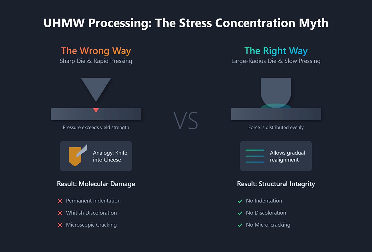
- Phenomenon: Using standard sharp V-shaped dies designed for metals often leads to permanent indentation and whitish discoloration on the inner bend—signs of molecular damage—or even microscopic cracking.
- Root Cause: A sharp punch concentrates pressure along a narrow line, instantly exceeding UHMW’s yield strength. For a relatively soft polymer, this does not induce yielding but catastrophic collapse of its microstructure—like pressing a knife blade into a piece of cheese. Slow, gentle pressing combined with large-radius dies (R-corner tooling) distributes force more evenly, allowing the molecular network to gradually stretch and realign rather than being brutally cut apart.
3. Misconception Three: Ignoring “Springback” and “Thermal Expansion–Contraction” — The Culprits Behind Dimensional Failure
- Phenomenon: After cooling, the bend angle is far less than intended (for example, a target of 90° results in 110°), or the entire piece warps and twists, throwing dimensional tolerances completely off.
- Root Cause: This is the most central—and most counterintuitive—aspect of the science governing UHMW bending.
- The “Double Impact” of Springback: UHMW doesn’t just exhibit substantial springback—it also unfolds over time. The bend may look perfect right after forming, but as internal stresses gradually relax over several hours or even days, the polymer chains slowly “creep” and rebound, increasing the bend angle further. The only effective countermeasure is precise over-bend compensation, reinforced by pressure-hold cooling to lock the molecular chains into their new configuration.
- The “Civil War” of Thermal Expansion and Contraction: Because of UHMW’s poor thermal conductivity, the outer surface cools and contracts rapidly upon exposure to air after bending, while the core remains hot and expanded. This uneven, opposing shrinkage generates immense internal stress, violently twisting the part like a rope under tension. That’s why it’s critical to use a fixture to secure the shape and ensure slow, uniform overall cooling (for instance, by letting it rest in ambient air). This allows the internal "war" to settle before it spirals out of control.
III. The Field Manual: Mastering UHMW Press Brake Forming in Four Stages
Successfully forming UHMW on a press brake is not a single isolated technique but a tightly integrated, precision-driven system. It begins with respect for the raw material, continues through meticulous tool preparation, and culminates in the artistic control of heat and timing. These four stages operate like interlocking gears—any lapse in one will unravel the entire process and result in scrap.
3.1 Stage One: Preparation (Where 80% of Success Is Defined)
In most failed bending attempts, the root cause doesn’t lie in the press brake itself but in a lack of thorough preparation. By this stage, 80% of success has already been determined. Though it may appear routine, preparation holds the genetic code of the final part’s quality.
- Material Inspection and Cleaning: This is where professionalism begins. Before starting, inspect UHMW sheets with the same scrutiny you’d apply to optical components. Ensure there are no scratches, contaminants, or hidden transport-related flaws. Even a minor surface imperfection can amplify under heat and stress, becoming the origin of catastrophic cracking. Thoroughly clean the surface with lint-free wipes and isopropyl alcohol (IPA) to remove any trace of grease or mold release.
- Edge Finishing: Cut the UHMW sheet precisely to the final dimensions, but remember—cutting is only the first step. The real key is edge refinement. Burrs or chips left by sawing act as lethal stress concentrators. Polish, scrape, or chamfer all edges until smooth and rounded. A rough edge is a pre-engineered “tear line” waiting to happen during bending.
- Process Characterization and Batch Control: This often-overlooked step separates professionals from amateurs. Different manufacturers and even different production batches of UHMW can vary in molecular weight, additive composition, and residual internal stress. These subtle but crucial differences directly affect flexibility, flow behavior, and springback after cooling.
- Key Action: For any new or high-precision project, conduct a process characterization test. Take a small piece of the exact same material (a coupon) and run it through the full heating–bending–cooling cycle. This establishes the material’s optimal heating duration and actual springback angle for that batch.
- Golden Rule: For any given project, always use material from the same batch. Mixing batches is a surefire route to inconsistent bend angles and unpredictable quality.
3.2 Stage Two: Equipment and Tool Setup (The Secret to Flawless Bends)
Using UHMW on a standard press brake designed for metal is like chopping firewood with a scalpel. Specialized adjustments are not optional—they define professionalism.
Heating System: Precision and Uniformity Are the Soul
- Preferred Option: Industrial Hot-Air Circulation Oven. For small and medium parts or consistent production runs, this is the only reliable way to achieve uniform, stable heating of the entire sheet to the target temperature.
- Alternative: Strip Heaters or High-Power Heat Guns. Suitable for large sheets or localized bends. The key is to use a non-contact infrared pyrometer to actively scan and verify that the entire bend line maintains a consistent temperature within the 130°C–150°C “golden window.” Never rely on dial readings or guesswork.
Bending Dies: Abandon Sharp Edges, Embrace Smooth Curves
- First Commandment: Large Radii Are the Lifeline. This is the single most critical modification. Discard all sharp V-dies and pointed punches designed for metal—they are UHMW’s nemesis.
- Punch: The bending radius (R) at the material contact point should be at least three times the material thickness, preferably larger.
- Die: The V-groove opening should be at least eight to twelve times the material thickness.
- Professional Approach to “Mark-Free” Bending:
- Buffer Pad: Place a high-hardness (typically Shore 90A) polyurethane sheet on top of the lower die. It cushions pressure under load, distributing stress evenly and preventing surface indentation on the soft UHMW.
- Mirror Polishing: Polish all die surfaces in contact with UHMW to a mirror finish. This minimizes friction, ensuring smooth, fluid material movement.
Cooling Fixture (Jig): Guardian of the Final Shape
- Why It’s Essential: This is your ultimate defense against UHMW’s stubborn “elastic memory” and aggressive “thermal contraction.” Prepare a precisely crafted jig or fixture before heating that can hold the part securely at its final target angle.
- Design Notes: The fixture can be made of metal, wood, or high-density composites, but it must match the final geometry accurately. It should provide firm support while hot and maintain constraint as the part cools and contracts.
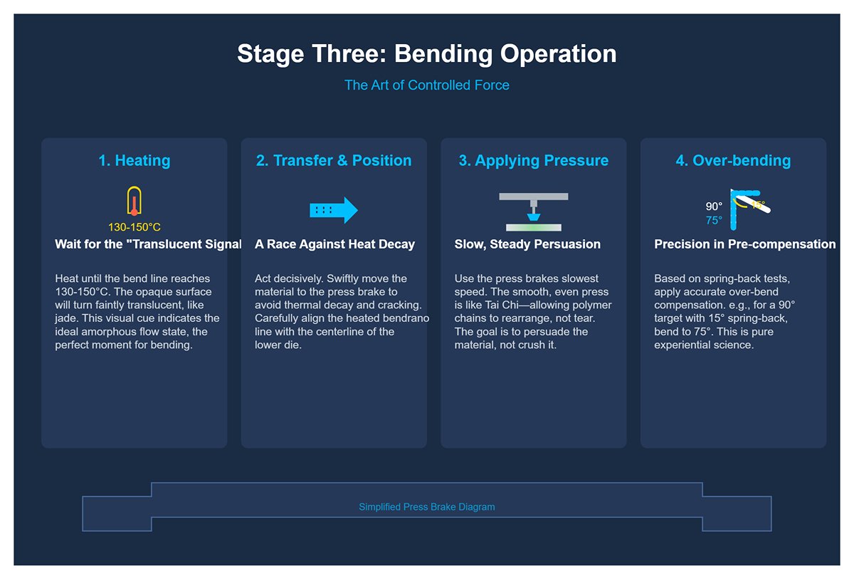
3.3 Stage Three: Bending Operation (The Art of Controlled Force)
This is the most visually engaging and experience-driven stage. It’s not a brute-force compression but an elegant choreography of heat, time, and pressure.
- Heating: Wait for the “Translucent Signal” Place the prepared UHMW sheet into the preheated oven or heat it evenly using your chosen tool. Continuously monitor with an infrared pyrometer until the bend line temperature stabilizes between 130°C and 150°C. At this point, a crucial visual cue will appear: the originally opaque, milky surface of UHMW will turn faintly translucent, with a jade-like luster. This visual shift indicates that the material has reached its ideal amorphous flow state—the perfect moment to execute the bend.
- Transfer and Positioning: A Race Against Heat Decay — Once the ideal temperature is reached, act decisively and swiftly to transfer the material from the heating area to the press brake. This step is a literal race against thermal decay; any hesitation will cause the surface temperature to drop, increasing the risk of cracking. Carefully align the heated bend line with the centerline of the lower die.
- Applying Pressure: Slow, Steady Persuasion — Activate the press brake and set the ram to its slowest speed. Using pressure and speed far below typical metal forming parameters, press down smoothly and evenly. The process should feel like the controlled flow of Tai Chi—continuous and balanced—allowing the polymer chains enough time to stretch, slide, and rearrange instead of being torn apart. Your goal is not to crush the material, but to persuade it.
- Over-bending: Precision in Pre-compensation — Based on the spring-back angle determined in Stage One testing, apply accurate over-bend compensation. For instance, if the target bend is 90° and tests show a 15° rebound, you must bend to 75°. This step represents pure experiential science, grounded in rigorous preliminary measurement.
3.4 Stage Four: Cooling and Shaping (Locking in the Final Form)
This is the decisive battle that determines the part’s dimensional accuracy and long-term stability—the final test against the material’s inherent physical properties.
- Immediate Clamping: Securing Victory — Right after completing the over-bend on the press brake, raise the upper die and swiftly transfer the still-hot and pliable part to the pre-set cooling fixture. Secure it firmly. The time from leaving the die to reaching the fixture is counted in seconds. Any delay allows spring-back to steal away the angle you’ve just earned.
- Absolute Restriction: No Forced Cooling — Leave the clamped part to cool naturally at room temperature under fixture restraint. Cooling must be completely natural and gradual. Never use fans, compressed air, or water to accelerate the process, as forced cooling causes violent, uneven contraction between outer and inner layers, leading to internal “stress warfare.” The result: severe warping, twisting, or even delayed cracking days later.
- Patience: Allow Complete Stabilization — Depending on part thickness and size, full cooling and internal stress rebalancing can take anywhere from tens of minutes to several hours. A reliable indicator is simple: the part must feel completely cool to the touch, with no residual warmth. Until then, do not remove it from the fixture.
- Final Verification — Once fully cooled, release the part from the fixture. Use a precision protractor and caliper to check angles, dimensions, and flatness. A successful UHMW bend should show smooth, flawless inner and outer surfaces—no whitening, no microcracks, exact angles, and an even, distortion-free profile. It is a product forged by both science and craftsmanship.
IV. Troubleshooting and Process Optimization: From Competence to Excellence
Mastering the basic UHMW bending procedure is only the ticket to enter the professional arena. The real challenge lies in consistently producing high-precision, defect-free parts—true “zero-flaw” performance. Achieving this requires shifting from reactive problem-solving to proactive prevention and transforming scattered experience into a quantifiable, repeatable process control system. This chapter serves as your advanced guide from a “competent operator” to a “process master.”
4.1 Four Common Defects: Diagnosis and Solutions
In UHMW bending practice, nearly all failure cases trace back to four typical defect types. Understanding the physical roots behind them is the first step toward precise corrective action—laying the foundation for developing true expert intuition.
| Defect Type | Symptoms & Diagnosis | Root Cause Analysis (Why It Happens) | Advanced Solution (How to Fix It) |
|---|---|---|---|
| 1. Cracking | Symptoms: Catastrophic fractures appear along the outer bend radius, with smooth, shell-like fracture surfaces. | 1. Insufficient Temperature: The number-one culprit. When the material remains in its glassy, “hard candy” state, molecular chains cannot slide to relieve stress, and massive tensile force tears them apart. 2. Overly Small Bend Radius: Sharp dies act like blades, concentrating stress along a single line and exceeding the tensile limit. 3. Excessive Pressing Speed: Rapid impact pressure leaves no time for the polymer network to respond, stretch, and rearrange. | - Targeting Core Temperature: Use an infrared thermometer to ensure the core of the bend area reaches 130–150°C — not just the surface. Remember, UHMW is a poor heat conductor. - Die Optimization: Use punch radii at least 3–5× the material thickness and a die opening 8–12× the thickness to provide room for smooth deformation. - Slow, Creep-Like Bending: Reduce the press speed dramatically, making the bend gradual and continuous — more “persuasion” than “force.” |
| 2. Surface Damage | Symptoms: - Stress whitening along the inner bend. - Scratches or dents from tool contact, ruining the finish. | 1. Localized Overstress: Stress whitening visually indicates irreversible microstructural damage from excessive tension or compression. 2. Tool Friction or Contamination: UHMW’s low hardness means any rough or dirty metal tool will scar its surface. 3. Pressure Concentration: Die edges or punch tips focus pressure on tiny areas, collapsing the soft surface. | - Use Cushion Pads or Sacrificial Layers: Line the lower die with a high-hardness (Shore 90A) polyurethane mat or a thin UHMW film to absorb and distribute pressure, preventing dents and scratches. - Polish Tooling to a Mirror Finish: Make all tool-contact surfaces mirror-smooth to minimize friction, letting the material glide effortlessly. - Perform Dust-Free Operations: Before each run, use compressed air and clean lint-free cloths to ensure tools are free of debris or metal particles. |
| 3. Warping & Distortion | Symptoms: Finished parts lose flatness after cooling, showing twists, bows, or wave-like warps resembling “pretzels.” | 1. Uneven Cooling: The prime cause. Outer layers cool and shrink first, launching an internal “stress war” that twists geometry. 2. Uneven Heating: Prior nonuniform heating embeds residual stress before bending. 3. Insufficient Support During Cooling: While still flexible at high temperature, gravity or poor placement leads to sagging and distortion. | - Design Full-Contact Cooling Fixtures: Support all surfaces of the part, not just the bend. It acts like a “peacekeeping force” restraining shrinkage stress conflicts. - Ban Forced Cooling: Cool slowly and naturally at room temperature. Any accelerated method (fans, water) triggers a catastrophic stress battle. - Pre-Bend Annealing: For high-precision components, anneal slightly below forming temperature, then slow-cool to release most residual stress beforehand. |
| 4. Angle Inaccuracy | Symptoms: Final bend angles deviate significantly from design (usually larger) or vary within the same batch. | 1. Molecular Memory: UHMW’s ultra-long polymer chains inherently rebound elastically — springback is expected, not accidental. 2. Process Parameter Fluctuations: Minor variations in heat, dwell, or cooling rate directly affect springback magnitude. 3. Batch Differences: Different UHMW batches have subtle variations in molecular weight and crystallinity, altering springback behavior. | - Create a “Springback Compensation Database”: Ditch guesswork. Record actual springback values for various thicknesses and batches under defined conditions to calculate precise overbend angles. This transforms bending from craft to science. - Standardize Parameters as SOP: Fix heating time, temperature, dwell period, etc., in seconds and degrees Celsius for absolute repeatability. - Apply Pressure-Hold Cooling: After initial bend, maintain pressure for 3–5 seconds to release immediate stresses before transferring to cooling fixtures — effectively reducing springback. |
4.2 Dimensional Accuracy Assurance Strategies
To progress from merely “acceptable” to truly “excellent,” fixing defects reactively is not enough. You must implement a systematic accuracy assurance framework — one that integrates deep material understanding into every stage of your design and process.
- Strategy 1: Incorporate a Stress-Relief Stabilization Step This often-overlooked technique can greatly enhance final precision. UHMW accumulates internal stress throughout manufacturing and cutting. For parts with tight tolerances (±0.5 mm or less), a dedicated stabilization stage must be included in the process flow.
- Pre-Bend Stabilization: After cutting the sheet, do not heat or bend immediately. Lay it flat on a smooth surface at room temperature for at least 2–4 hours (24 hours recommended for high-precision parts) to naturally release edge stress generated during cutting.
- Post-Bend Stabilization: After removing the cooled part from the fixture, avoid immediate secondary machining. Let it rest for several hours to release any residual stress suppressed during cooling, achieving the most stable and accurate final dimensions.
- Strategy 2: Turn Thermal Expansion and Contraction from a ‘Problem’ into a ‘Parameter’ UHMW’s enormous thermal expansion coefficient — roughly 15 times that of steel — is a primary source of dimensional error. Instead of treating it as a nuisance, precisely quantify it and incorporate it into all design and process calculations.
- Golden Rule: Post-Machining Principle The cornerstone of dimensional accuracy — perform all precision machining (holes, slots, threads) only after bending and full thermal stabilization. Any holes pre-made before bending will inevitably shift or distort once the material undergoes intense heating and subsequent cooling shrinkage.
- Design for “Cold Dimensions,” Calculate for “Hot Dimensions” Every drawing, fixture, and mold design must be based on the material’s final target dimensions at room temperature (cold dimensions). However, when designing heating and bending operations, you must reverse-calculate the part’s expanded dimensions at elevated temperatures—typically between 130–150°C (hot dimensions)—to ensure it fits properly into molds and fixtures after expansion, avoiding interference or misalignment.
- Strategy 3: Apply Simplified Process Control (SPC-Lite) The path to transforming UHMW bending from an intuition-driven “craft” into a data-guided “science” lies in consistent documentation and analysis. You don’t need sophisticated statistical software—a simple tracking sheet can deliver powerful insights.
- Create a Process Card: Set up a straightforward tracking card for each production batch.
- Record Key Parameters: For every operation, document the material batch number, sheet thickness, heating temperature and time, actual bend angle, dwell time, ambient temperature, and cooling method and duration.
- Measure and Track Outcomes: Systematically measure the final angle and key dimensions of every fifth to tenth part, and note them on the card.
- Analyze and Feed Back: When dimensions begin to drift or exceed tolerance, your response should not be guesswork. Instead, review your recorded data to pinpoint the most likely variable causing the deviation—for instance, the first piece after a lunch break when ambient temperature shifted—and make precise adjustments. This data-driven feedback loop is the only reliable route to continuous improvement and superior quality.

V. Strategic Decision: Is the Press Brake Truly the Best Choice?
After mastering the intricate art of UHMW press brake forming, a higher-level question emerges—one that tests your strategic engineering insight: In your specific production scenario, is investing effort into “taming” a press brake truly the only, or even the optimal, path to success?
The answer is no. Press brake forming is merely one tactical approach within the vast landscape of UHMW processing methods. It offers unmatched speed and accessibility—a true “lightning strike” advantage—but also operates within strict boundaries.
As an exceptional engineer or decision-maker, your true value lies not only in solving the technical question of how to execute a process but in addressing the strategic question of whether it is worth doing at all. That requires a panoramic view—evaluating all viable manufacturing options and choosing wisely amid the constant trade-off between cost, efficiency, and quality.
5.1 When to Use Press Brake Forming for UHMW
Despite its challenges, in well-defined scenarios, employing a suitably modified and precisely tuned press brake to heat-bend UHMW remains a highly practical, efficient, and cost-effective option. Its Zone of Optimal Application can be clearly summarized in four key conditions:
- Simple Geometries: The Champion of 2D Linear Bends When your product design requires a single-direction, linear bend within a two-dimensional plane, the press brake is the undisputed productivity leader. Classic examples include simple L-, U-, or Z-shaped brackets, conveyor guides, protective shields, or wear-resistant liners. Always remember its limits: once three-dimensional curves, varying radii, or non-parallel bends are introduced, the press brake quickly reaches its functional boundary.
- Small to Medium Batch Production: Economical and Agile Setup flexibility is a major advantage. Compared to dedicated molds, press brake tooling—especially when using universal solutions like polyurethane pads—incurs negligible cost. This makes it ideal for prototype fabrication, small batch runs (from a handful to several hundred pieces), or one-off custom projects, eliminating the need for costly mold investments for new designs.
- Moderate Material Thickness: The Critical Control Zone Extensive engineering experience shows that press brake bending works best with UHMW sheets up to 6 mm (approximately 1/4 inch) thick. Beyond that, heating time, bending force, and the notoriously unpredictable spring-back increase exponentially, making precision control and cost management significantly more difficult.
- Leverage Existing Equipment: Maximizing Asset Value For workshops or factories that already own a press brake, using this “sunk cost” asset for suitable UHMW bending tasks is the most economically intelligent choice. It avoids upfront capital investment in specialized equipment such as large hot presses or thermoforming units, thus maximizing utilization of existing resources.
In essence, choosing press brake forming for UHMW is a strategic decision grounded in convenience, flexibility, and pragmatic economics. For tasks involving simple shapes, small to medium production quantities, and thin to moderately thick sheets, it delivers exceptional performance and value.
5.2 A Panoramic Process Comparison: Strengths and Trade-offs of Alternatives
When part design exceeds the press brake’s technical limits—or when production demands higher throughput, precision, or geometric complexity—you must look beyond press brake forming. The following table serves as your strategic “dashboard,” offering a clear visual of each major process technology’s technical fit and economic cost model.
| Process Method | Ideal Application Scenario | Geometric Complexity | Accuracy/Tolerance | Economic Batch Size | Tooling/Setup Cost | Material Utilization | Key Advantage | Primary Challenge |
|---|---|---|---|---|---|---|---|---|
| Press Brake Bending | Simple 2D linear bends (guards, rails) | Low | Moderate | Low to Medium | Very Low | High | Highly flexible, extremely low cost, uses existing equipment | Limited to straight bends, difficult springback control, unsuitable for thick plates |
| CNC Machining | High-precision 2D/3D profiles, holes, and slots (gears, sliders, precision parts) | Very High | Extremely High | Low (prototype/custom) | None (or basic fixtures only) | Low | Ultimate accuracy and design freedom | High material waste, slow processing, internal stress generation |
| Compression Molding | Thick-walled, large-size, simple structures (blocks, bushings, plates) | Low | Moderate | Medium to High | High | Extremely High | Maximizes material performance, allows ultra-thick parts | Long cycle times, unsuitable for thin or complex shapes |
| Thermoforming | Large, thin-walled, 3D curved shells (covers, trays, liners) | Medium | Moderate | Medium | Moderate | Medium | Ideal for large curved surfaces, balanced cost and efficiency | Uneven wall thickness, lower precision than other molding methods |
| Injection Molding | Ultra-high-volume production of small, complex parts (medical implants, precision fasteners) | High | High | Very Large | Very High | High | Highest production efficiency, near-perfect repeatability | Extremely poor UHMW melt flow, high technical and equipment thresholds |
In-depth Analysis: Strategic Insights Beyond the Table
- CNC Machining: The Price of Absolute Precision This is the ultimate approach for achieving final precision and the archetype of subtractive manufacturing. When your design calls for intricate curves, precise hole arrays, or micron-level tolerances, CNC machining is often the only viable path. But its challenges are equally formidable: UHMW’s incredible toughness prevents brittle chip formation, producing gummy, string-like swarf that easily entangles the cutting tool. Its exceptional wear resistance quickly dulls standard tooling, and its poor thermal conductivity traps heat in the cutting zone, leading to local melting instead of clean cutting—causing tool adhesion and degraded surface quality. Successful UHMW machining demands expensive, specialized tools (single-edge, highly polished, wide chip grooves), carefully tuned parameters (low speed, high feed rate), and efficient cooling systems. Consequently, both the time and cost of UHMW machining far exceed those of other engineering plastics.
- Compression Molding: Guardian of Material Integrity This is essentially the mother process used to produce UHMW stock shapes such as sheets and rods. UHMW powder is sintered and pressed under high temperature and pressure within a mold. When used directly for making parts, it’s ideal for simple, thick-walled, high-strength components. Its advantages are striking: nearly zero material waste (almost 100% utilization) and a slow, controlled cycle that preserves the polymer’s molecular structure and mechanical properties. However, the downsides are equally substantial—tooling is costly and heavy, while heating and cooling cycles can take hours, making the process unsuitable for thin-walled or geometrically complex parts.
- Thermoforming: The Cost-Effective Choice for Large Curved Surfaces In this process, a heated, softened UHMW sheet is vacuum-drawn or pressure-formed over a single-sided mold, essentially “dressing” the mold with plastic. It strikes an excellent balance between manufacturing cost and geometric complexity, making it ideal for large, lightweight covers, automotive liners, or equipment trays with gentle 3D contours. Although its dimensional accuracy and wall thickness uniformity are inferior to compression molding, its tooling cost (single-sided molds) and production cycle are far more economical—making it the go-to process for medium-volume, medium-precision curved components.
- Injection Molding: The Mass-Production Deity For most plastics, injection molding reigns supreme in high-volume manufacturing. But with UHMW, it becomes an epic technical challenge. The core issue lies in UHMW’s extraordinarily high melt viscosity—its molten flow is almost nonexistent, like attempting to inject warm taffy into a fine mold cavity. Achieving injection molding requires machines capable of generating immense injection pressures and molds strong enough to withstand them. As a result, this technique is reserved for only a few ultra-high-production (often millions of units) and high-value small parts, such as specific medical-grade implants. For 99.9% of industrial applications, however, it’s simply not a practical option.

In conclusion, choosing a manufacturing process is no longer a purely technical decision—it has evolved into a strategic business question about how best to allocate organizational resources. As a decision-maker, you must weigh your options across four key pillars to identify the optimal path toward commercial success:
- Geometry: Is the part linear or curved? 2D or 3D?
- Production Volume: Are you making 10 pieces or one million?
- Precision: Are tolerances at the millimeter or micron level?
- Cost: What is the acceptable range for unit cost and upfront tooling investment?
Within this expansive landscape of manufacturing options, the press brake plays the role of a nimble special forces operative—it can’t win every battle, but within its theatre of strengths, it is the fastest and most economical weapon at your disposal. Your task, as the strategic commander, is to deploy the right forces for every mission with precision and confidence.
VI. Conclusion
In summary, successfully forming UHMW in a press brake is an achievable goal, but it demands a specialized approach. By abandoning metalworking habits and instead mastering precise heating, custom tooling, and controlled cooling, fabricators can conquer UHMW's challenging properties.
While the press brake is ideal for simple, low-volume bends, a strategic assessment of alternative methods like CNC machining or compression molding is crucial for complex or high-volume projects. Ready to implement these techniques with confidence?
Don't let material challenges slow you down. The experts at ADH have the deep process knowledge and state-of-the-art equipment to help you achieve flawless results. You can explore our full range of machinery in our Brochures. Contact us today to discuss your UHMW forming project and get a solution tailored to your needs.


