I. What Is Bend Deduction?
Precision in sheet metal fabrication hinges on mastering the art of bend deduction calculations. Bend deduction is a critical aspect of press brake bending in precision sheet metal fabrication. The size of the workpiece, as depicted in a graphic design drawing, is different from its size in the bent state.
During the press brake bending process, the tension stretches the outer material, causing it to elongate, while the inner material is compressed. The neutral axis remains unaffected by pressure or tension. Hence, its length remains unchanged.

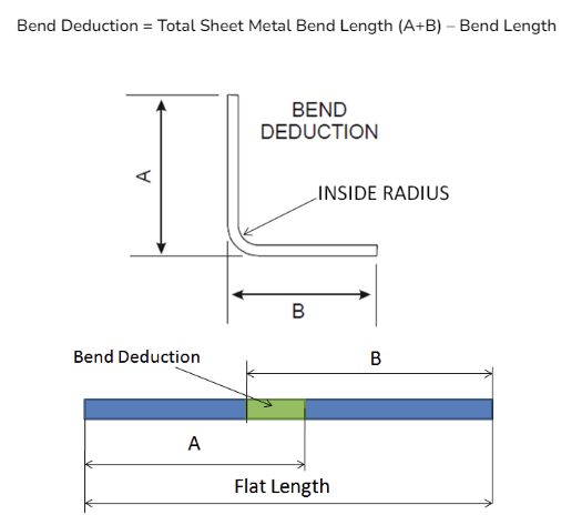
As a result of these changes, the size of the workpiece after bending is different from the size of the flat pattern in sheet metal part drawings. To achieve the correct flange length and the bending point, you need to calculate the sheet metal bend deduction, which represents the amount to be subtracted from the workpiece size after bending.
In simpler terms, Bend Deduction (BD) refers to the extent to which the sheet is stretched after the tension applied during bending is released. Thus, the value of bend deduction is equal to the difference between the total flange length and the total flat length.
II. How to Calculate Bend Deduction?
1. K-Factor in Bending
The parameters required for calculating bend deduction are based on material thickness, bending angle, bend radius, and K factor. The K factor, the ratio of the distance from the neutral layer to the inner surface of the sheet metal to the thickness of the sheet metal, is determined by the material thickness and bending method.
The term K-factor is used to show how much the neutral axis moves off center in a bend. The K-factor is determined by the properties of the material and the bend itself.
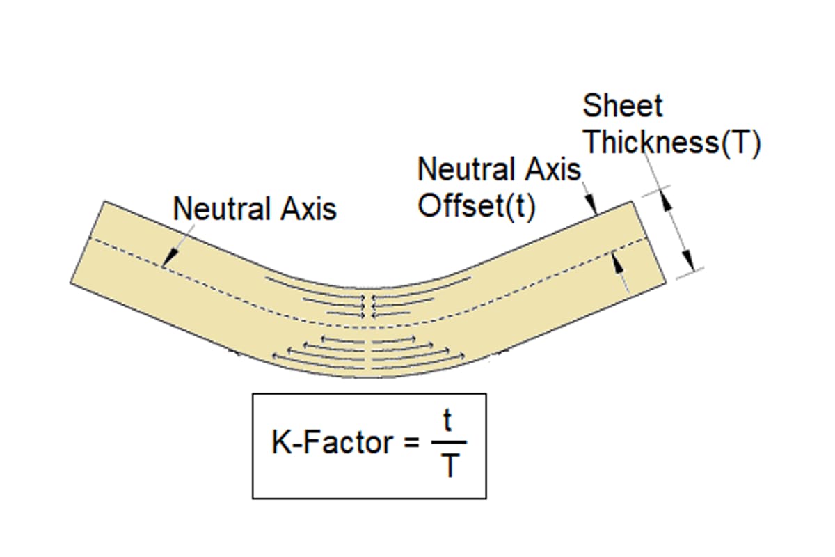
The formula for the K factor is as follows, easily workable with any scientific calculator:
K = t/T
Where t is the distance from the neutral line to the material edge, and T is the material thickness. The range for the K factor is generally between 0.3 and 0.5. Different materials and thicknesses affect the choice of the K-factor:
The most accurate K-factor comes from reverse-calculating based on actual test bends done on your own equipment, using your tooling and materials. Early in design, however, the table below can serve as a reasonable starting point—remember, it’s an estimate, not a definitive value.
| Material Type | R/T Ratio (Inside Radius / Thickness) | Free Bend K-Factor Range |
| Soft Materials (e.g. Aluminum 5052, 6061) | R < T | 0.35 - 0.40 |
| T ≤ R < 3T | 0.40 - 0.45 | |
| R ≥ 3T | 0.45 - 0.50 | |
| Medium Hardness Materials (e.g. Low Carbon Steel / CRS) | R < T | 0.38 - 0.42 |
| T ≤ R < 3T | 0.42 - 0.46 | |
| R ≥ 3T | 0.46 - 0.50 | |
| Hard Materials (e.g. Stainless Steel 304, 316) | R < T | 0.34 - 0.40 |
| T ≤ R < 3T | 0.40 - 0.44 | |
| R ≥ 3T | 0.44 - 0.50 |
The K-factor does not increase linearly. It rises with the R/T ratio but at a diminishing rate, approaching a limit of 0.5 as R/T becomes very large.
To see how our equipment can help you achieve precise and repeatable bends, feel free to browse our product Brochures.
2. Bend Allowance
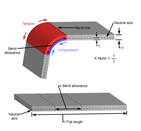
The bend allowance describes the length of the neutral axis between the bend lines, or in other words, the arc length of the bend. Bend allowance is the arc length of the neutral axis through the bend. It is important because it allows us to cut sheet metal precisely and produce a bent metal piece.
Calculate the bend allowance formula:

Where:
- B = Bend angle in degrees
- IR = Inside bend radius
- K = K factor
- MT = Material thickness
In practical operations, the inside radius (IR) can be measured using the following methods:
- Using a Bend Gauge: Place the bend gauge inside the bend and read the inside radius.
- Using Calipers: Place the inside measuring jaws of the calipers inside the bend and read the inside radius.
The inside radius is largely determined by manufacturing processes and tooling, not merely by the idealized values set in CAD by the designer.
For typical air bending, the inside radius (IR) is about 15%–20% of the V-opening width in the lower die for steel. In bottoming or coining, the inside radius is defined directly by the tip radius of the punch.
At the design stage, it’s essential to coordinate with the shop to understand tooling capabilities, ensuring the IR value used is realistic and manufacturable.
Material thickness can be measured using a vernier caliper or a micrometer:
- Vernier Caliper: Clamp the measuring jaws of the caliper around the material and read the thickness.
- Micrometer: Clamp the measuring faces of the micrometer around the material and read the thickness.
Never rely solely on nominal thickness from a datasheet—take multiple measurements across the sheet and use the average.
Although modern bend deduction charts are relatively accurate, older charts have serious variances.
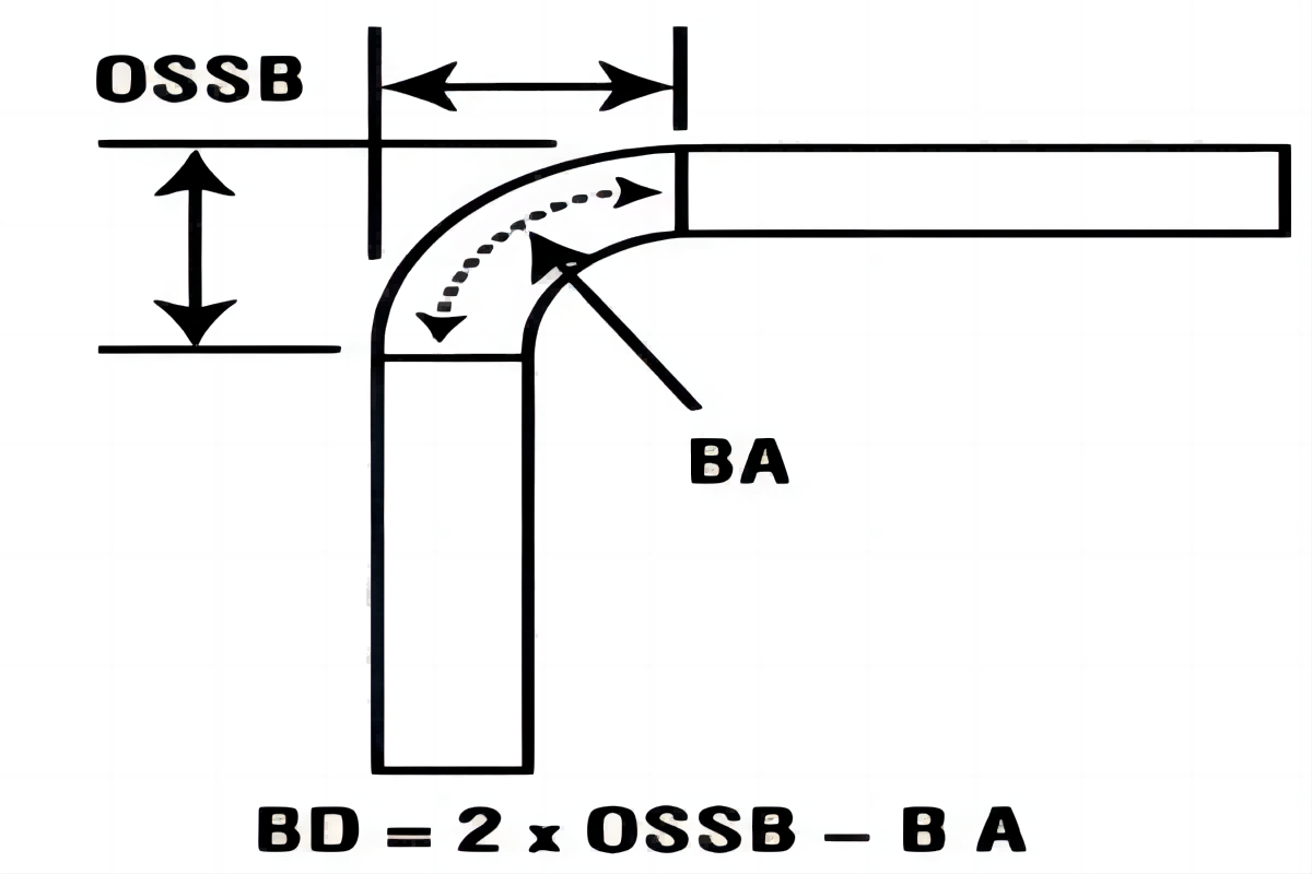
If we know the bend allowance (BA) and the outside setback (OSSB), we can quickly calculate the bend deduction.
BD=2 · OSSB - BA
The calculation formula of outside setback (OSSB) is:
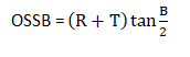
Where:
3. Bend Deduction
The Bend Deduction BD is defined as the difference between the sum of the flange lengths (from edge to the apex) and the initial flat length. If you know what size flanges you want to end up with after bending and need to calculate the size of the flat pattern to start with (and where to start your bend), Bend Deduction is what you want. For a comprehensive overview of how to achieve manufacturing accuracy through calculation, explore our guide on K-Factor Bend Allowance and Bend Deduction Precise Solutions.
When we know these parameters, the bend deduction calculation formula can also be:
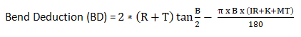
Where K represents the K factor, R and IR both represent the inner radius, T represents material thickness, B represents the bending angle, and MT also represents plate thickness.
4. Example Calculation
Using the two formulas we have explained, the sheet metal bending calculation is simple. To illustrate, let's calculate these parameters for a 90-degree bend with a material thickness of 2 mm and an inside radius of 3 mm, assuming a K factor of 0.42.
1. K Factor:
K=0.42
2. Bend allowance:
3. Outside setback:
4. Bend Deduction:
Mastering these calculations is fundamental to quality sheet metal fabrication. To see the advanced machinery that puts these principles into practice, feel free to download our product Brochures.
5. Adjustments for Different Materials and Thicknesses
(1) Adjusting the K-Factor
The K-factor is a ratio that represents the location of the neutral axis. It typically ranges from 0.3 to 0.5. Different materials and thicknesses affect the choice of the K-factor:
- Thin Materials: The K-factor is usually smaller, around 0.3.
- Thick Materials: The K-factor is usually larger, around 0.5.
- Material Type: For example, aluminum typically has a smaller K-factor than steel.

(2) Adjusting Bend Allowance and Bend Deduction
Different materials and thicknesses affect the calculation of Bend Allowance and Bend Deduction:
- Thin Materials: Bend Allowance and Bend Deduction values are smaller.
- Thick Materials: Bend Allowance and Bend Deduction values are larger.
- High-Strength Materials: Such as stainless steel, Bend Allowance and Bend Deduction values are larger because the material is harder to bend.
6. Practical Application Scenarios
(1) Measurement and Calculation Steps
- Measure Inside Radius and Material Thickness: Use a bend gauge or calipers to measure the inside radius, and use a vernier caliper or micrometer to measure the material thickness.
- Select the K-Factor: Choose an appropriate K-factor based on the material type and thickness.
- Calculate Bend Allowance: Use the formula to calculate Bend Allowance.
- Calculate Outside Setback: Use the formula to calculate Outside Setback.
- Calculate Bend Deduction: Use the formula to calculate Bend Deduction.
(2) Adjusting Calculation Methods
Adjust the calculation methods for different materials and thicknesses to ensure accuracy:
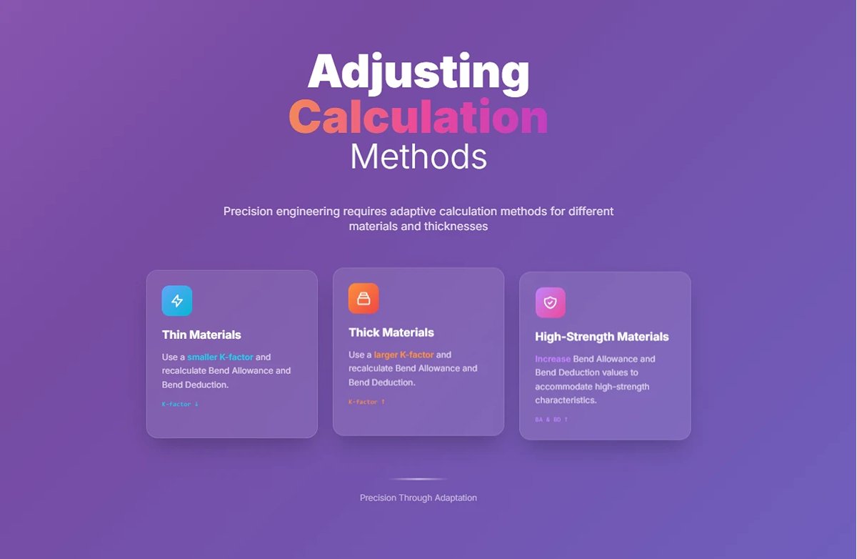
- Thin Materials: Use a smaller K-factor and recalculate Bend Allowance and Bend Deduction.
- Thick Materials: Use a larger K-factor and recalculate Bend Allowance and Bend Deduction.
- High-Strength Materials: Increase Bend Allowance and Bend Deduction values to accommodate the high-strength characteristics of the material.
Calculating all these values manually isn’t the only way to find the right dimensions for your material. If you’re using CAD software with sheet metal tools, you can usually input the K-Factor and the bend radius values directly into the software and it will give you the same reduced values. It just depends on what software you’re using.
5. Commercial Value in Focus
In the precision-driven world of manufacturing, even the smallest dimensional deviation can unleash a storm on the cost sheet. Exact bending deduction (BD) calculations are no longer a mere technical detail—they have become a strategic weapon, enabling companies to cut costs right from the design stage and forge a decisive competitive edge.
(1)Standardized Production Processes
Say goodbye to the old craft shop days of relying solely on a master’s “touch” and “experience.” Data-driven precision calculations make manufacturing predictable and repeatable, greatly enhancing product quality consistency. They also pave the way for full-scale automation—such as integration with CNC press brake systems—forming a crucial step toward Industry 4.0 and intelligent manufacturing.
(2)Dramatically Reduced Scrap Rates
Inaccurate flat length calculations are the most expensive “silent killers” in any sheet metal shop. A single miscalculation can turn an entire sheet of costly material—be it stainless steel, aluminum alloy, or even titanium—into scrap after the very first bend. Precision BD calculations eliminate this waste at the DNA level. In mass production, the cost savings can reach astronomical figures.
(3)Double the Assembly Efficiency
Picture a complex product made from dozens of sheet metal parts—if just one part's bend hole is off by 0.5 mm, the entire assembly line could grind to a halt. Rework, hammering, adjustments, waiting… all these hidden costs silently erode your profit. Accurate BD calculations ensure parts are perfectly consistent and interchangeable, enabling smooth, “Lego-like” assembly and elevating production rhythm to a whole new level.
III. Tools and Software for Automating Bend Deduction
1. Advanced Simulation and Calculation Tools
(1)Finite Element Analysis (FEA)
Finite Element Analysis (FEA) is a sophisticated tool used in many press brake software packages to predict how materials will deform during bending. Think of FEA as a virtual stress test that shows how the material will react under pressure, helping to ensure accurate bending results.
Leading manufacturers like LVD, Bystronic, ADH, and Trumpf use FEA to optimize bending setups, ensuring high-quality outcomes by accurately predicting springback, bend angles, and radii.

(2)Automated Bending Sequences
Software solutions such as PNBend by WiCAM, Bystronic, and Trumpf automate the creation of bending sequences based on material properties, bend angles, and tooling configurations.
For example, a manufacturer might use these automated sequences to produce a batch of metal brackets with consistent quality. By minimizing human error, these automated systems ensure that the calculated bend deductions are precise, leading to reliable and uniform production outcomes.
2. CAD/CAM Integration and Automated Calculations
(1)Seamless CAD/CAM Integration
Many press brake software solutions integrate directly with CAD systems, allowing users to import design files (e.g., DXF, STEP) and automatically generate bending programs. This seamless integration eliminates manual data entry errors and speeds up the workflow from design to production.
Software like PNBend and those from LVD and Bystronic support this integration, facilitating the accurate calculation of bend allowance and bend deduction within the CAD environment.
(2)Bending Calculators and Formulas
Tools like the Bending Calculator by SendCutSend automate the calculation of bend allowance and bend deduction using formulas that consider bend angle, material thickness, inside bend radius, and the K-factor. This bend allowance calculator and bend deduction calculator provide precise values, ensuring accurate flat pattern lengths before bending, which is essential for high-quality production.
3. Offline Programming and Real-Time Adjustments
Software solutions enable offline programming, allowing operators to create and verify bending programs without occupying the press brake, thus reducing machine downtime and increasing throughput. Additionally, advanced press brake software includes real-time sensing and adjustment capabilities.
Sensors monitor parameters like force and angle during the bending process and make adjustments to account for material inconsistencies. This combination ensures that the calculated bend deductions are maintained with high precision throughout production.
4. Tooling and Setup Optimization
(1)Tool Library Management
Press brake software often includes a tool library management feature, where operators can manage a wide range of punches, dies, and specialty tools. This simplifies the selection process for various jobs and ensures that the tools are compatible with the press brake's specifications. Managing a well-organized tool library is crucial for maintaining accurate bend deductions and ensuring smooth production.
(2)Automated or Manual Tooling Recommendations
The software can suggest optimal tooling setups based on job requirements, material type, and bend geometry. These recommendations save time during setup and improve consistency across batches, ensuring that the calculated bend deductions are precisely applied.
5. Comprehensive Bending Simulation
(1)3D Simulation
Press brake software like PNBend, LVD, and Bystronic offers 3D simulation functions that visualize the entire bending process. This helps detect potential issues such as collisions and tool interference before production begins, ensuring that the calculated bend deductions are feasible and accurate.
Including diagrams or images of these simulations can significantly enhance understanding and engagement, providing a clear visual representation of the bending process.
IV. Common Challenges and Solutions in Bend Deduction
1. Handling Complex Scenarios
(1) U-Channels (Multiple Same-Direction Bends)
A U-channel is essentially the sum of two simple bends. The logic is straightforward: calculate the bend deduction for each bend separately, then subtract the total of these values from the overall external length.
Formula:
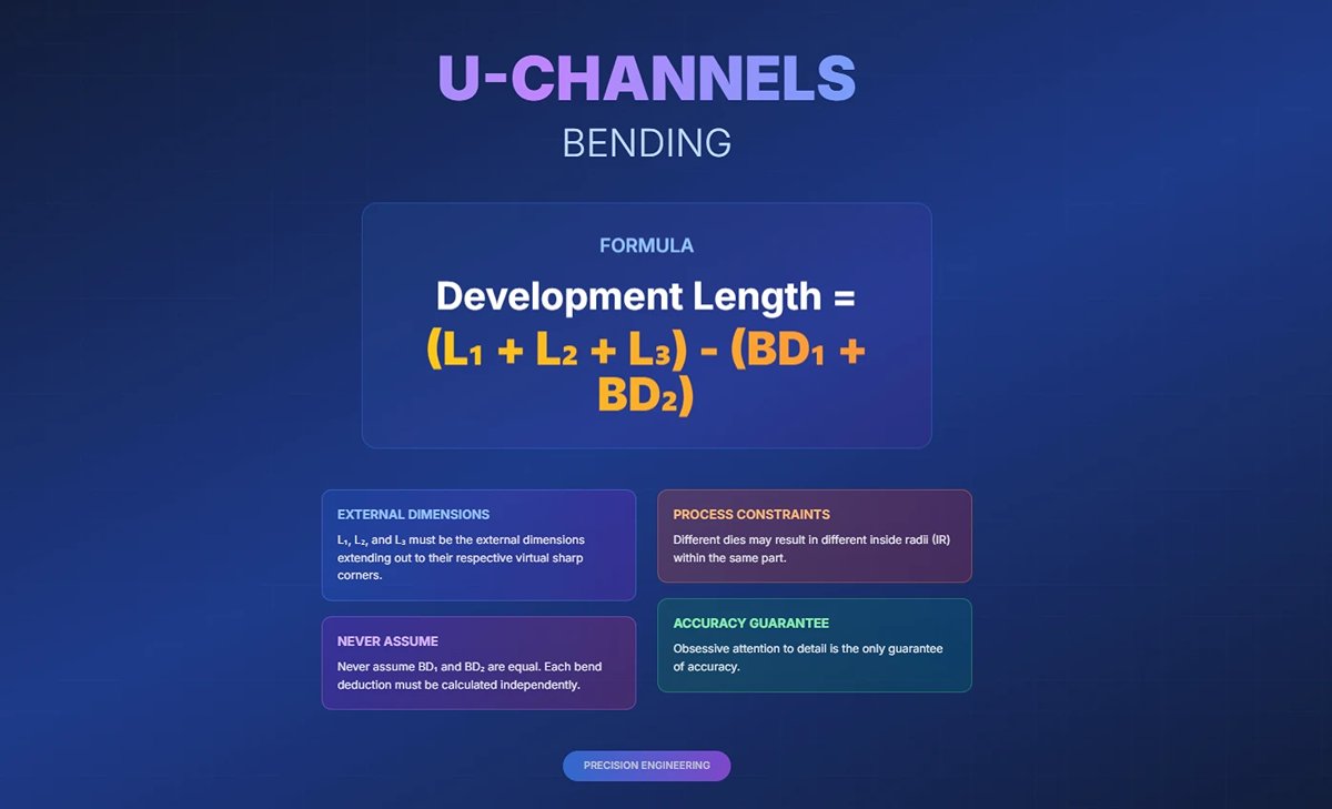
Development Length = (L1 + L2 + L3) - (BD1 + BD2)
Here, L1, L2, and L3 must be the external dimensions extending out to their respective virtual sharp corners. Never assume BD1 and BD2 are equal. Even within the same part, if different dies are used due to process constraints—resulting in different inside radii (IR)—each bend deduction must be calculated independently. Obsessive attention to detail is the only guarantee of accuracy.
(2) Non-90° Acute and Obtuse Bends
This is a common pitfall for beginners and a litmus test for true expertise. The root of most errors lies in misunderstanding the “bend angle A.” Commit this rule firmly to your engineering intuition:
1)Acute bends (e.g., a finished internal angle of 60°)
If your goal is a 60° internal angle, picture a flat sheet at 180° and ask: how far must it rotate to reach the target? The answer is 180° - 60° = 120°.
Therefore, in all formulas (BA, OSSB), the value of A must be entered as 120. Entering 60 directly will lead to costly and disastrous miscalculations.
2)Obtuse bends (e.g., a finished internal angle of 135°)
Following the same logic, the rotation from 180° is 180° - 135° = 45°, so the value for A in the formula should be 45.
Non-90° bends, especially acute ones, involve more severe material deformation. This increases the unpredictability and magnitude of springback, meaning stronger overbend compensation must be factored in during the design stage.
(3) Z-Bends (Reverse Bends)
A Z-bend comprises two adjacent bends in opposite directions. The development length is calculated just like a U-channel: compute BD1 and BD2 separately, then subtract both from the total length.
Core formula:
Development Length = Total External Length L - (BD1 + BD2)
The real challenge with Z-bends isn’t the math—it’s manufacturability. The flat section between the two bends (the middle leg) has a strict minimum length requirement. It must be long enough to sit securely on the die during the second bend without causing the first formed flange to collide with the brake frame or punch.

A general rule is that the middle leg should be at least twice the die-opening width (V-opening), and often more. It’s easy to draw a theoretically correct Z-bend in CAD, but overlooking this detail will leave you with a design that can never be produced.
2. Common Challenges
(1)Misestimating K-Factor
1)Challenge
The K-factor, representing the neutral axis's position relative to material thickness, varies based on material type, thickness, bend radius, and bending method. Misestimating it can lead to incorrect bend deductions and flat pattern dimensions.
2)Solution
- Use material-specific K-factor tables or software tools for accurate values.
- Conduct empirical testing by bending sample pieces and measuring the resulting dimensions to determine the actual K-factor for specific materials and setups.
- Regularly update K-factor values based on tooling changes or material variations.
(2)Springback Effects
1)Challenge
Springback occurs when the material partially returns to its original shape after bending due to internal stress release. Ignoring springback can result in inaccurate bend angles and dimensions.
2)Solution
- Overbend the material slightly to compensate for springback.
- Use tighter die clearances or apply coining (a method that plastically deforms the material) to reduce springback.
- Utilize advanced CNC press brakes with built-in compensation algorithms for precise adjustments.
(4)Cracking or Overbending Issues
1)Challenge
Cracking occurs when the inner bend radius is too small or the material's grain direction aligns with the bend line. Overbending can distort the part or cause structural weaknesses.
2)Solution
- Increase the punch's bending radius or select a softer material to prevent cracking.
- Adjust blanking layout to ensure grain direction is perpendicular to the bend line.
- For overbending, calculate appropriate compensation using bend deduction formulas and consider using annealed materials for better ductility.
(5)Measurement Errors
1)Challenge
Inaccurate measurements of material thickness, inside radius, or bend angle can propagate errors throughout the calculation process.
2)Solution
- Double-check all measurements using calibrated tools like micrometers or digital calipers.
- Implement quality control procedures to verify input parameters before bending operations.
- Use CAD software with integrated measurement tools to reduce manual errors.
(6)Cumulative Effects in Multi-Bend Scenarios
1)Challenge
Errors in individual bends accumulate across multiple bends, leading to significant deviations in final part dimensions.
2)Solution
- Calculate bend deductions for each bend individually, considering variations in angles and radii.
- Use simulation software to model multi-bend parts and predict cumulative effects before fabrication.
- Validate final dimensions against design specifications after each bend stage.
V. Applications of Bend Deduction in Fabrication
1. Flat Pattern Development
(1)Role in Manufacturing Processe
Bend deduction is essential for determining the correct flat blank dimensions before bending. It ensures that the final part matches the design specifications after forming by accounting for material elongation and compression during bending.
(2)Importance in Reducing Waste
- Accurate flat pattern calculations minimize material waste, leading to cost savings and sustainable manufacturing practices.
- By avoiding errors in blank size, manufacturers reduce scrap and rework, improving efficiency.
(3)Ensuring Fit During Assembly
Properly calculated bend deductions ensure that bent parts fit seamlessly during assembly, avoiding misalignment or gaps that could compromise structural integrity or functionality.
(4)Example:
A component with flange lengths of 2” and 3” and a bend radius of 0.25” at 90° requires subtracting the bend deduction (e.g., 0.293”) from the flange total length (5”) to determine the flat blank length (4.707”).
2. Press Brake Programming
(1)Configuring Backgauge Settings
1)The backgauge is a critical component of press brakes, used to position the sheet metal accurately for bending operations. Proper programming of the backgauge ensures precise bends by accounting for bend deduction.
2)Adjustments include:
- Setting backgauge depth based on material thickness and bend angle.
- Positioning backgauge fingers to hold the material securely during bending.
(2)Automation and CNC Integration
Modern CNC press brakes use advanced software to automate backgauge positioning based on bend deduction values. This reduces setup times and ensures consistent results across production runs.
For example, a CNC system can calculate the total elongation (bend deduction) and adjust the backgauge position accordingly to achieve precise flange dimensions.
(3)Applications in Complex Bends
Multi-axis backgauges enable intricate bending operations by allowing adjustments for parts with multiple bends or varying angles, increasing flexibility in low-volume, high-mix production environments.
(4)Example
A press brake operator programs a backgauge position for a flange length of 2” with a bend deduction of 0.1274”. The system adjusts automatically to ensure the correct placement of the bend line relative to the punch nose.
3. Industry Use Cases
(1)Aerospace Industry
- Precision is paramount in aerospace manufacturing, where components like brackets and fuselage panels must meet strict tolerances to ensure safety and performance.
- Advanced bend deduction calculations are used to produce lightweight yet strong parts while minimizing material waste.
- Case Study: A manufacturer uses detailed bend deduction formulas to fabricate complex brackets for aircraft fuselages, achieving exact fits and reducing structural stress.

(2)Automotive Industry
Bend deduction is critical for creating chassis components, body panels, and brackets that require high dimensional accuracy for proper assembly.
The process ensures that parts fit together seamlessly in vehicles, contributing to safety and performance standards.
Example: Chassis components bent using precise deductions ensure alignment during welding and assembly, reducing rework costs.
(3)Electronics Manufacturing
In consumer electronics, accurate bends are essential for creating enclosures and frames that house delicate internal components.
Bend deduction calculations allow manufacturers to produce sleek designs with tight tolerances, ensuring proper fitment and functionality.
Example: Laptop casings fabricated using bottoming techniques achieve sharp bends with minimal springback, providing durability and aesthetic appeal.
Ⅵ. Advanced CAD Application
Now we’ve reached the pinnacle of the efficiency revolution—the point where you move from “good” to truly “great.” The core idea is simple: stop treating your CAD software as a generic drawing tool with idealized parameters, and start transforming it into a manufacturing simulator that precisely mirrors your shop floor’s real-world capabilities. In other words, it’s time to get your design software to start telling the truth.
1. Unlocking and Customizing Bend Tables
Nearly every mainstream CAD platform (SolidWorks, Inventor, Fusion 360, etc.) hides a remarkably powerful feature within its sheet metal module—the ability to abandon the universal K-factor formula entirely, and instead use a custom Bend Table.
Think of it as a built-in, highly accurate “process database.” It’s essentially a spreadsheet that works like this: when the software detects you’re designing a bend with a specific material, thickness, internal radius, and angle, it doesn’t calculate using a theoretical formula—it looks up and applies the single, absolutely correct bend deduction value you’ve entered, based on real-world measurement data.
(1)How to Make Your Software Tell the Truth
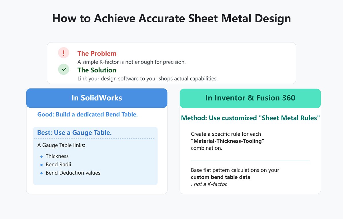
In SolidWorks, don’t settle for simply entering a K-factor in the sheet metal feature. Start by building a dedicated bend table for your company.
For an expert-level approach, use a “Gauge Table.” A gauge table is essentially an advanced version of a bend table—it tightly links material thickness, all possible bend radii for that thickness, and the corresponding bend deduction values.
This means that, during design, available bend radii aren’t arbitrary numbers—they’re restricted to a controlled drop-down list that matches your shop’s tooling limits exactly.
In Inventor or Fusion 360, the same concept is applied through deeply customized “Sheet Metal Rules.” You can create a separate rule for each “material-thickness-tooling” combination (e.g., “2mm-304 Stainless Steel-V12 Die”), and in each rule, base flat pattern calculations not on a K-factor but on your custom bend table with precise bend deduction data.
(2)Why Is This So Critical?
A custom bend table is the lifeline that bridges digital design with physical manufacturing, ensuring consistency at scale—its importance simply cannot be overstated.
Enforce a unified standard and eliminate designer-to-designer variation: It ensures every designer—whether a seasoned pro or a new hire—works with the same rigorously verified manufacturing data that reflects your actual capabilities. This eradicates the classic problem of “Parts from Designer A fit perfectly, but Designer B’s are slightly off.”
1)Achieve true “Design-as-Manufacture”:
When your bend table is built on your shop’s actual tooling, materials, and springback data, CAD-generated flat pattern drawings (DXF files) stop being “theoretical documents” and instead become “manufacturing instructions” ready for immediate use. They need no secondary adjustments—ready for laser cutting and CNC bending—dramatically shortening lead times and eliminating communication errors.
2)Capture and pass on expertise:
It turns the subtle, experience-driven know-how of veteran fabricators into quantifiable, transferable, and scalable digital assets. This preserves critical process knowledge for the long term, protecting it from being lost when people leave and turning it into a lasting foundation for growth.
3)Drive maximum profitability:
By preventing scrap and rework caused by incorrect flat dimensions right from the design stage, you enable high-precision, adjustment-free assembly—the core technical foundation of lean manufacturing and profit optimization. When your software tells the truth, your financial statements will show an even more beautiful truth.
Ⅶ. FAQs
1. How does bend allowance relate to bend deduction?
Bend allowance (BA) and bend deduction (BD) are closely related in sheet metal bending. Bend allowance measures the additional length along the neutral axis due to bending, while bend deduction calculates the amount to subtract from the flat pattern to achieve the final dimensions.
Essentially, BD is derived by subtracting BA from the sum of the flange lengths, ensuring accurate placement of bend lines. Both concepts are crucial for precise bending, with BA providing the added material length and BD adjusting the flat pattern to account for this added length, ensuring the part dimensions are correct post-bending.
2. How do material properties affect bend deduction calculations?
Material properties significantly affect bend deduction calculations. Factors like material thickness, bend radius, and the K factor influence how the material deforms during bending.
Thicker materials and smaller bend radii typically require larger bend deductions due to greater internal stress and deformation. The bend angle also plays a crucial role, with larger angles necessitating more substantial deductions.
Additionally, the material's K factor, which indicates the neutral axis position, impacts the extent of stretching or compressing during the bend. Understanding these properties ensures accurate bend deduction calculations, leading to precise fabrication outcomes.
3. What are the common geometric factors to consider in bend deduction?
Common geometric factors to consider in bend deduction include the bend radius, bend angle, material thickness, K-factor, and outside setback.
The bend radius affects material stretching, while the bend angle determines the degree of the bend. Material thickness influences both the bend allowance and K-factor, which is the ratio of the neutral axis position to the material thickness.
The outside setback is the distance from the material edge to the bend apex. These factors are critical for accurate bend deduction calculations, ensuring precise dimensions in sheet metal bending operations.
Ⅷ. Conclusion
In this article, we delved into the concept of Bend Deduction and its calculation methods. Bend deduction refers to the amount of material we need to take from the metal sheet to achieve the correct length.
By calculating the bend deduction, we can accurately adjust the bend points and length of the flanges to ensure that the final dimensions of the workpiece meet the design specifications.
Calculating Bend Deduction requires considering parameters such as material thickness, bend angle, bend radius, and the K-factor. Mastering this knowledge is crucial for any professional involved in bending operations.
ADH Machine Tool is a professional manufacturer of sheet metal processing machines with extensive experience in the metal forming and fabricating industry. We offer press brakes, shears, fiber laser cutting machines, panel benders, and more.
For more information on bending and our products, please feel free to contact us or visit our website for press brake information. Get a quote today!


