I. Introduction
After a sheet metal part is bent, its actual size may differ from the size depicted on its flat pattern drawing. This is due to the external tension that stretches the sheet and internal compression caused by extrusion.
The total length increases, so it's essential to calculate the sheet metal bend deduction. Bend deduction is the difference between the total length of the flanges after bending and the total flat length.
Bend deduction charts simplify calculations with pre-determined values based on material properties, angles, and tooling. They ensure accurate layouts, promote consistency, reduce errors, and minimize waste. These charts are essential for precise sheet metal fabrication.
II. Using Bend Deduction Charts and Software Tools
2.1 Breaking Down the Core Concept
Bend deduction is one of the most frequently overlooked yet critical values in flat pattern calculations. It is formally defined as: the amount you must subtract from the combined outer dimensions of two flanges (measured to an imaginary intersection point) to obtain the correct flat length.
Imagine you need to make a simple L-shaped bracket with outer edge lengths of 50 mm and 30 mm. A naïve assumption would be to simply cut a flat piece measuring 50 + 30 = 80 mm. But this would be wrong, as it double-counts the material in the bend.
Bend deduction exists precisely to correct this kind of simplistic mistake.
The 90° bend is by far the most common in sheet metal work—most enclosures, brackets, trays, and housings are built from 90° angle segments.
Its ubiquity means shops have accumulated extensive standardized data, while its geometry’s simplicity allows quick and accurate deduction values to be obtained from charts or simplified formulas.
Even so, high-precision manufacturing must account for factors like sheet thickness tolerances, inside bend radius, K-factor, and springback. Otherwise, even a millimeter-scale error can compromise assembly quality.
2.2 Understanding Bend Deduction Charts
Bend deduction charts are essential in sheet metal fabrication, providing quick references for adjustments needed to achieve precise bends. They include details on material thickness, bend angle, inside radius, and K-factor, simplifying the process for fabricators.
How to Use Bend Deduction Charts
(1)Identify Key Parameters
Measure the material thickness (T), determine the bend angle (B), measure the inside radius (IR), and select the appropriate K-factor (K) for the material and operation.
(2)Locate the Values on the Chart
Find the row corresponding to the material thickness, and then the column that matches the bend angle. Cross-reference with the inside radius and K-factor to find the bend deduction value.
(3)Apply the Bend Deduction
Subtract the bend deduction value from the total flat length to determine the final dimensions of the sheet metal part.
The bending chart provides an intuitive way to visualize the effect of different parameters such as bend angle, thickness of the metal, inside radius and k-factor, etc. The material thickness will be measured in decimal form, not by the gauge number.
To determine the bend angle properly you must use the complementary angle of the part feature. It is important to convert the included angle to the complimentary angle before you perform the calculation. The inside radius will be the finished radius of the included angle.
For instance, if the bend angle is known to be 90 degrees, you can refer to the 90 degree bend deduction chart to find the desired parameters. The below Microsoft Excel chart is for even numbered gauges 8 through 24 and has a default K-Factor of .33 for each.
Many software packages like Solid Works and Solid Edge will let you incorporate a bend deduction chart into its calculations when you develop a flat pattern. As you can see the bend deduction calculator is below, which can also serve as a simple bend allowance calculator:
Miño, L. Bend Allowance Calculator. Available at: https://www.omnicalculator.com/physics/bend-allowance. Accessed: Jun 20, 2024.2.3 Software Tools for Bend Deduction
(1)Autodesk Fusion
Several software tools streamline the process of calculating bend deduction, enhancing accuracy and efficiency in sheet metal fabrication.
Autodesk Fusion streamlines sheet metal forming simulations by allowing users to input material thickness, bend angle, inside radius, and K-factor. The software then automatically calculates the bend allowance and deduction. It also enables users to create and edit custom bend tables for precise results.
(2)SOLIDWORKS
SOLIDWORKS offers a range of bend allowance types, including K-Factor, Bend Allowance, and Bend Deduction. Users can select from predefined equations or use Excel spreadsheets to generate the necessary values, providing flexibility and ensuring accurate bend calculations.
(3)CAD Software Integration
Many CAD systems allow for the direct input of K-Factor and bend radius values, which the software then uses to calculate the bend deduction. This integration enables seamless transitions from design to fabrication, reducing the risk of errors and improving overall efficiency.
(4)Practical Applications of Bend Deduction Tools
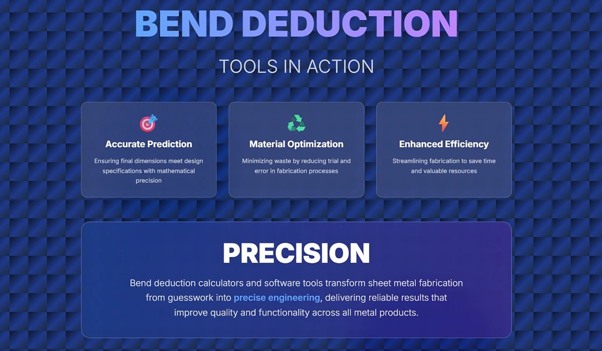
Bend deduction calculators and software tools are crucial for engineers, fabricators, and designers. They aid in:
- Accurate Prediction: Ensuring final dimensions meet design specifications.
- Material Optimization: Minimizing waste by reducing trial and error.
- Efficiency: Streamlining the fabrication process to save time and resources.
Using bend deduction charts and software tools helps fabricators achieve precise, reliable results, improving the quality and functionality of sheet metal products.
III. Calculate Bend Allowance and Bend Deduction
We discussed the bend allowance and bend deduction calculation in a previous article. The bend deduction is often confused with bend allowance. Thus, understanding the bend allowance or bend deduction is a crucial first step to understanding how sheet metal parts are fabricated for the metal forming and fabricating industry.
3.1 Bend Allowance
Bend allowance refers to the length of the neutral axis between the bend lines, and it is the length added to the flange length to get the bend allowance.
Bend Allowance Calculation Formula:

The bend allowance is the amount of the neutral axis that bends. The bend allowance formula takes into account the geometries of bending and the properties of your metal to determine the bend allowance.
3.2 Bend Deduction
Formula for Bend Deduction:
In sheet metal terms, bend deduction (BD) and bend allowance (BA) are like identical twins—similar in appearance but opposite in nature and purpose. Confusing them is the number one cause of dimensional errors.
Here’s a table that makes the distinction crystal clear:
A deeper insight: they’re not isolated concepts—they’re linked by a purely geometric value called the Outside Setback (OSSB), which is the distance from the imaginary outer corner to the point where the bend starts.

This formula shows that the amount you must deduct (BD) is essentially the geometric overlap you’ve double-counted (2 × OSSB) minus the actual physical material length needed in the bend (BA). Understanding this removes the need for rote memorization.
Where:
- R is the inside radius of the bend
- T is the material thickness
- B is the bend angle
- IR is the inside radius
- K is the K-factor
- MT is the material thickness
- OSSB is the outside set back.
- If you need to calculate flange lengths after bending, use bend allowance.
- If you need to determine flat pattern dimensions before bending, use bend deduction.
The bend deduction is defined as the material you will have to remove from the total length of your flanges to arrive at the flat pattern. Protective coatings, variations in the alloy and thickness as well as many other small factors all add up to give you bend deductions unique to your operation.
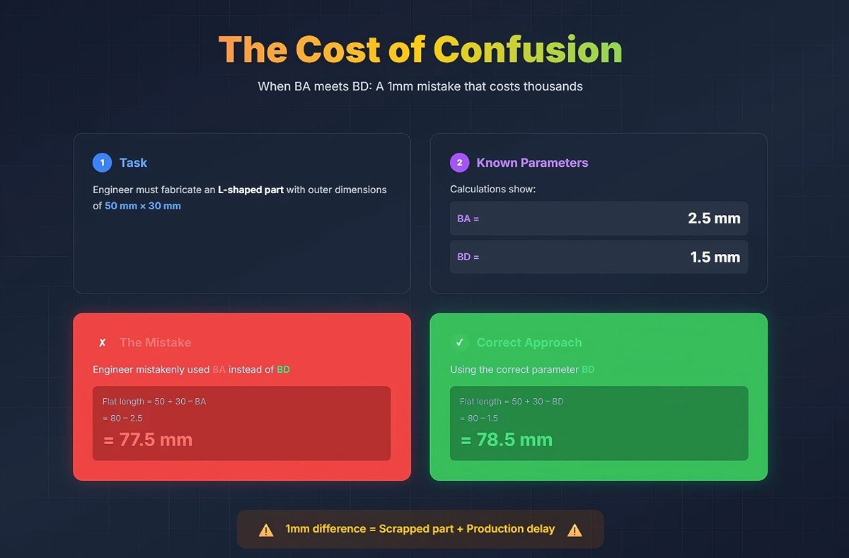
Here’s a costly example of what happens when these are confused:
(1) Task: An engineer must fabricate an L-shaped part with outer dimensions of 50 mm × 30 mm.
(2) Known parameters: Calculations show BA = 2.5 mm, BD = 1.5 mm for the required bend.
(3) The mistake: The engineer mistakenly used BA instead of BD. Flat length = 50 + 30 – BA = 80 – 2.5 = 77.5 mm.
(4) The correct approach: Flat length = 50 + 30 – BD = 80 – 1.5 = 78.5 mm.
By using the wrong value, they created a 1 mm error in the blank size. After bending, the flanges could not both meet the 50 mm and 30 mm targets, leaving the part unusable. In high-precision or mass production, such an error is fatal.
3.3 Example Calculation
Assume we have a metal sheet with a thickness of 2 mm, a bend radius of 3 mm, a bend angle of 90 degrees, a K factor of 0.3, and an inside radius of 3 mm. We need to calculate consequently the bend deduction.
Substituting the values:
Calculate each part:
So:
Calculate the second part:
Final calculation:
This calculation formula is used to develop the flat pattern length of sheet metal and the size of the workpiece.
IV. Step-by-Step Guide to Calculating Bend Deduction
4.1 Step-by-Step Guide
Step 1: Determine the K-Factor
The K-factor is crucial and can be determined based on the material properties and thickness. For example, a stainless steel sheet might have a K-factor of 0.44.
Step 2: Calculate the Bend Allowance (BA)
The formula for bend allowance is:
Step 3: Calculate the Outside Setback (OSSB)
The outside setback is calculated as:
- ( R ) is the inside bend radius
- ( T ) is the material thickness.
Step 4: Calculate the Bend Deduction (BD)
There are two common formulas for calculating bend deduction:
Formula 1:
Where OSSB is the outside setback, BA is the bend allowance.
Formula 2:
Where:
- ( R ) is the inside bend radius
- ( T ) is the material thickness
- ( A ) is the bend angle in degrees.
4.2 Example Calculation
Let's calculate the bend deduction for a 2mm thick stainless steel sheet with a 90° bend and a 3mm inside bend radius, using a K-factor of 0.44:
Calculate the Bend Allowance
Calculate the Outside Setback
Calculate the Bend Deduction using Formula 1
V. Factors Affecting Bend Deduction
5.1 Material Properties
Material properties such as type, thickness, elasticity, and hardness play a significant role in determining bend deduction values during sheet metal fabrication.
(1)Material Type:
| Material | Strength Characteristic | Ductility Characteristic | Typical K-Factor Range | Bend Deduction Trend | Notes / Precautions |
|---|---|---|---|---|---|
| Steel | High strength | Lower ductility | ~0.45 | Larger | Neutral axis closer to inner radius |
| Aluminum | Lower than steel, lightweight | Higher ductility, easy to process | 0.33–0.42 | Smaller | Over-bending can cause cracking |
| Stainless Steel | High strength, corrosion resistant | Medium ductility | Higher than carbon steel (no fixed value) | Larger | Springback effect is noticeable |
| Titanium | Extremely high tensile strength | Low ductility | Tends to be higher | Larger | Increase inner bend radius to prevent cracking |
(2)Material Thickness:
1)Thicker materials exhibit greater deformation during bending, resulting in larger bend deductions. For example, a 4mm-thick steel sheet will require a larger deduction than a 1mm-thick sheet of the same material.
2)Thin materials tend to have smaller deductions due to reduced deformation.
(3)Elasticity and Hardness:
1)Harder materials (e.g., stainless steel) experience less compression on the inside of the bend but more stretching on the outside, shifting the neutral axis outward and increasing bend deduction values.
2)Softer materials (e.g., aluminum) allow greater compression and stretching, resulting in smaller deductions.
5.2 Bend Geometry
The geometry of the bend—specifically the inside radius, bend angle, and flange lengths—has a direct impact on bend deduction calculations.
(1)Inside Radius:
A smaller inside radius increases material deformation, requiring larger bend deductions.
A larger inside radius reduces stress concentration, resulting in smaller deductions.
(2)Bend Angle:
Larger angles (e.g., 120°) produce more significant material elongation, increasing the required deduction.
Smaller angles (e.g., 45°) involve less elongation and therefore smaller deductions.
(3)Flange Lengths:
Longer flanges may amplify material elongation effects during bending, requiring more precise adjustments in calculations.
(4)Role of the K-Factor:
The K-Factor is a property of the material substrate you are bending. This property reflects how the material stretches when formed, and will vary depending on the bend method.
where t is the distance from the neutral axis to the inner surface of the material, and T is the material thickness. A higher K-factor indicates that the neutral axis is closer to the center of the material (typical for thicker or harder materials).
5.3 Bending Methods
Different bending methods—air bending, bottoming, and coining—affect both the final bend radius and the required deduction values.
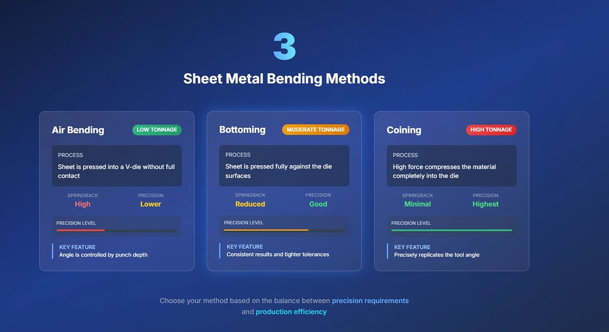
(1)Air Bending:
- The punch presses the sheet into a V-shaped die without fully contacting its bottom.
- The final bend angle depends on how far the punch descends into the die.
- This method requires lower tonnage but results in greater springback, requiring adjustments in bend deduction calculations.
(2)Bottoming:
- The sheet metal is pressed fully into contact with the bottom die surface.
- Produces more consistent results with reduced springback compared to air bending.
- Requires moderate tonnage and provides tighter tolerances for bend angles.
(3)Coining:
- High tonnage forces compress the sheet metal completely into the die cavity, ensuring precise replication of punch and die angles.
- Minimal springback occurs due to full material conformity with tooling.
- Best suited for applications requiring high precision (e.g., aerospace components).
| Bending Method | Tonnage Requirements | Springback | Precision |
| Air Bending | Low | High | Moderate |
| Bottoming | Moderate | Low | High |
| Coining | High | Minimal | Very High |
5.4 Material-Specific Adjustments
Different materials require specific adjustments during bending due to their unique mechanical properties:
| Material | Bending Precautions |
|---|---|
| Aluminum | Use a slightly larger inner radius to prevent cracking. Slightly over-bend during forming to compensate for springback caused by ductility. |
| Stainless Steel | Increase tonnage due to high tensile strength. Use specialized tools to effectively control springback. |
| Titanium | Increase the inner radius (1.5–2 times material thickness) to avoid cracking. Be careful when over-bending, as its low ductility makes it prone to stress cracking. |
| High-Strength Steel | Due to lower elasticity, higher tonnage and larger bending radii are required compared to mild steel. |
VI. Common Mistakes and Best Practices in Bend Deduction Calculations
6.1 Common Mistakes
(1)Miscalculating Bend Radius
One common error in bend deduction calculations is incorrectly estimating the bend radius. The actual achieved inside radius should be used rather than estimated values, especially in air forming processes. Using an incorrect bend radius can significantly impact the accuracy of bend deduction.
(2)Ignoring Material Properties and Using the Wrong Thickness Measurement
Accurate material properties and measurements are crucial for precise bend deduction calculations. Different metals have varying properties such as flexibility, strength, and elasticity, which affect how they bend. Additionally, using the wrong thickness measurement can affect the K-factor and subsequently the bend deduction calculations. Always ensure the correct material properties and thickness measurements are used in your calculations to avoid inaccuracies.
(3)Material Variation
Even within the same material grade, differences in material strength and grain direction can impact the bend deduction. These variations need to be accounted for to achieve accurate results. Failing to consider these factors can lead to discrepancies between calculated and actual dimensions.
(4)Incorrect Bending Method
Using the wrong bending method in calculations, such as bottom bending instead of air bending, can lead to differences between expected and actual bends. Ensure that the bending method used in calculations matches the method applied in the fabrication process.
(5)Not Accounting for Spring Back
Spring back is a phenomenon where metals tend to return partially to their original form after being bent. This needs to be compensated for by slightly overbending the material, which should be included in the bend allowance calculation. Failing to account for spring back can result in inaccurate bends.
6.2 Best Practices
(1)Use of K-Factor
The K-factor is essential for accurate bend deduction calculations. It ranges between 0.3 and 0.5 for most metals and bending operations. The K-factor indicates the ratio between the distance of the neutral axis and the material thickness. Using an appropriate K-factor ensures precise calculations.
(2)Accurate Formulas and Calculations
The bend deduction (BD) formula takes into account the material thickness (T), bend angle (B), inside bend radius (R), and K-factor. The correct formula is: [ BD = 2 \cdot OSSB - BA ] where OSSB is the outside setback and BA is the bend allowance. Ensuring the use of accurate formulas and calculations is critical for precise results.
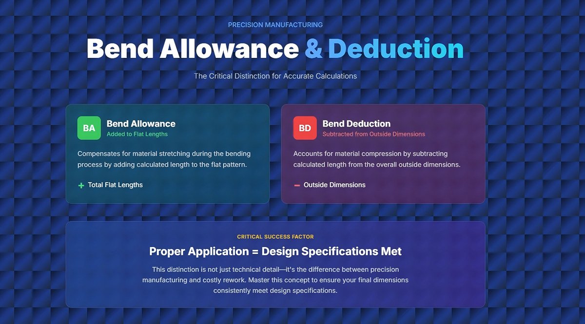
(3)Utilizing Bend Allowance and Bend Deduction Correctly
Bend allowance (BA) is added to the total flat lengths, while bend deduction (BD) is subtracted from the total outside dimensions. This distinction is critical for accurate calculations. Proper application of these values ensures the final dimensions meet the design specifications.
(4)Using Bend Deduction Charts and Software
While bend deduction charts can be useful, it is more accurate to calculate the BD based on actual achieved inside radius and material properties. CAD software with sheet metal tools can also be used to input the K-factor and bend radius values directly to obtain accurate dimensions. Utilizing these tools helps enhance precision and efficiency.
(5)Double-Checking Calculations
It is essential to double-check all factors such as bend radius, material properties, and thickness measurements to ensure accurate results. This includes verifying the calculations against the machine's output and material variations. Regularly reviewing and validating calculations helps prevent errors and discrepancies.
VII. FAQs
1. What Is Bend Deduction and Bend Allowance?
2. How to Calculate Bend Deduction?
3. Bend Allowance Chart
4. What is the difference between bend deduction and bend allowance?
Bend deduction and bend allowance are crucial yet distinct concepts in sheet metal fabrication. Bend allowance refers to the arc length of the bend along the neutral axis, which remains unchanged during bending. It is used to determine the total material length required. In contrast, bend deduction accounts for material deformation and is the length subtracted from the total length to achieve accurate final dimensions.
While bend allowance is added to the flat length to calculate the total length needed, bend deduction adjusts the flat pattern by compensating for material stretch and compression during bending. Understanding these differences ensures precise bending calculations.
5. Why is understanding bend deduction important in sheet metal fabrication?
Understanding bend deduction is crucial in sheet metal fabrication because it ensures accurate flat pattern layouts, leading to precision and proper fit in assemblies. It promotes consistency in production, minimizes material waste, and simplifies the manufacturing process.
Additionally, it accounts for material stretch and springback, ensuring dimensional accuracy. Mastering bend deduction enhances production planning and quality control, ultimately resulting in high-quality, reliable components that meet design specifications, as discussed earlier.
VIII. Conclusion
The value of bend deduction can be calculated not only through a formula but also using a deduction chart. To gain further knowledge about sheet metal bending, you can explore the ADH website blog for more informative content and products.
We have over 20 years of experience manufacturing hydraulic press brakes, shears, and fiber laser cutting machines, which are highly performance and efficient. Get an instant quote for your precision sheet metal fabrication projects now!


