The different types of press brakes each offer unique advantages, and understanding them is a key strategic decision impacting profitability and precision. This guide demystifies their core technologies and ideal applications, helping you choose a machine that secures a long-term competitive edge.
I. Strategic Foundation: Why Choosing the Right Press Brake Is Crucial for Manufacturing Success
In the grand chessboard of manufacturing, every decision to invest in a press brake is a strategic move that shapes your future. This is no exaggeration. Many decision-makers see it merely as a capital expense—a tool for bending sheet metal.
But that view barely scratches the surface. A high-quality press brake is far more than a station on the production line: it anchors your quality system, drives your production rhythm, and directly influences your profit margins and market competitiveness. A poor choice translates into years of hidden costs; a wise investment becomes a powerful lever for leaner, smarter, and faster operations.
This chapter reveals why a machine that may appear ordinary can have such a profound impact on your business landscape.
1.1 The Core Value of a Press Brake: More Than Bending Metal—It Shapes Competitiveness
The true worth of a modern press brake lies in how deeply it empowers manufacturing processes. It is no longer an isolated workstation, but a pivotal link in the value chain, bridging upstream design and downstream assembly.
Modern press brakes are foundational to manufacturing, acting as the physical anchor for quality by ensuring precise bending that dictates downstream assembly tolerance and overall product geometry. They set the pace for agile, high-mix, low-volume production, with advanced features like quick-change tooling and offline programming that enhance responsiveness and equipment effectiveness.
These machines also function as dual optimizers for cost and sustainability; energy-efficient drives dramatically reduce power consumption, lowering operational expenses and the carbon footprint. Crucially, they serve as a system for preserving expertise by digitizing the knowledge of skilled operators through embedded libraries and algorithms, thereby ensuring process consistency and converting craftsmanship into a replicable digital asset. To further deepen your understanding of bending fundamentals and achieve mastery in forming techniques, explore the Finger Brake Guide: Mastering Bending.
1.2 Decision Impact: How One Machine Shapes Your Product Precision, Productivity, and Profitability
Selecting a press brake is essentially setting the ceiling for your product accuracy, production efficiency, and profitability. Every technical specification you choose will be magnified in daily operations.
A press brake's value is determined by its ability to drive profit through a combination of precision and true operational efficiency. Precision stems from a chain of factors—including machine rigidity, synchronization, and deflection compensation—that ensure consistent bend angles and minimize scrap. True efficiency, however, is not measured by ram speed but by total order completion time, which is optimized through offline programming and quick-change tooling that reduce setup and changeover delays.
Ultimately, these elements of high precision and efficiency increase throughput and reduce waste, making the Total Cost of Ownership—which accounts for long-term energy use, maintenance, and reliability—a more critical metric for profitability than the initial purchase price.
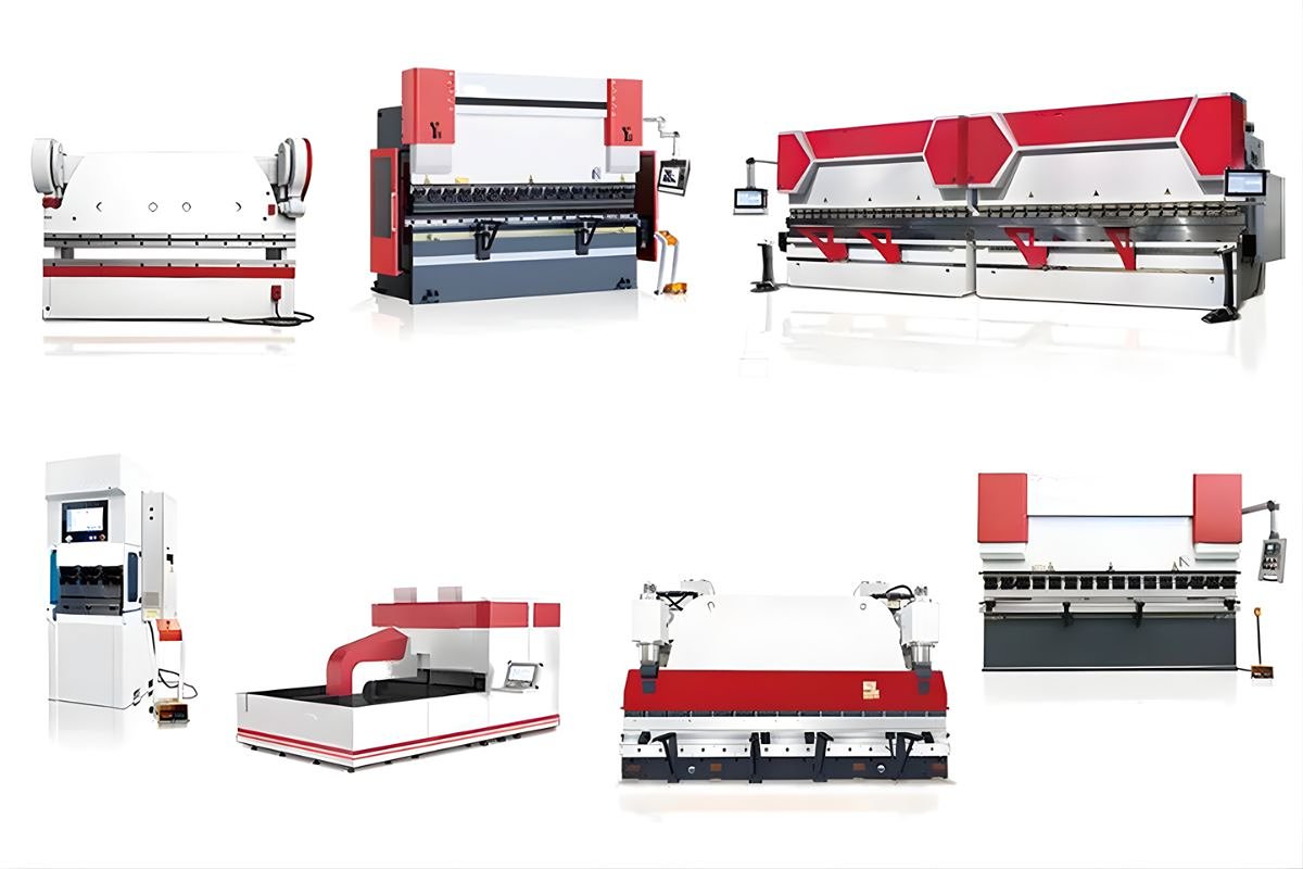
1.3 Cognitive Map: Overview of the Five Main Press Brake Families and Their Key Differences
| Type | Principle/Mechanism | Key Features | Ideal Applications |
|---|---|---|---|
| Mechanical Press Brakes | Uses a flywheel and clutch system. | High speed and efficiency; limited stroke and force adjustment. | High-volume processing of simple, thin-sheet parts. |
| Hydraulic Press Brakes | Controls hydraulic oil to drive cylinders. | Immense tonnage; adjustable pressure and speed; versatile. | Wide range of materials, from thin sheets to thick plates. |
| Servo-Electric Press Brakes | Servo motors directly drive ball screws or belt systems. | High precision, energy-saving, rapid response, exceptional repeatability, no hydraulic leaks. | High-precision, thin-sheet applications and clean environments. |
| Electro-Hydraulic Press Brakes | Servo motors drive hydraulic pumps on demand. | Combines hydraulic force with servo control; efficient and responsive; high tonnage. | A balanced choice for performance and cost. |
| Panel Benders | The workpiece is clamped while movable tools perform all bends. | High automation efficiency; excels at large panels and complex geometries; limitations in workpiece shape/thickness. | Handling large panels and complex multi-bend geometries. |
II. In-Depth Analysis: Classification and Operating Principles of Core Press Brake Technologies
2.1 Drive System Classification: The Evolution of the Power Source
The drive system is the heart of a press brake, defining how force is generated and transmitted. Its evolution reflects a shift from the pursuit of sheer speed toward a balanced emphasis on precision, energy efficiency, and operational flexibility.
For readers looking for detailed illustrations and technical parameters, you can explore ADH Machine Tool for comprehensive insights into industrial press brake solutions.
2.1.1 Mechanical Press Brake: Speed Classic, Efficiency Driven
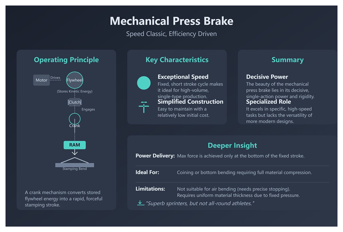
- Operating Principle: At its core lies a traditional crank-and-link mechanism. A motor drives a flywheel at high speed, storing substantial kinetic energy. When the clutch engages, this energy is released in an instant, with the crank transforming rotational motion into the ram’s forceful, rapid up-and-down stroke—delivering the bend with a stamping action.
- Key Characteristics:
- Exceptional Speed: The stroke cycle is fixed and extremely short, making it unbeatable for high-volume production of a single part type.
- Simplified Construction: Easy to maintain and relatively low initial purchase cost.
- Deeper Insight: The beauty of mechanical press brakes lies in their decisive, single-action power. Maximum force is achieved only at the very end of the stroke (bottom dead center), with a fixed stroke length. This makes them ideal for coining or bottom bending, where full material compression is required. However, such rigidity limits their ability to perform air bending, where precise stopping positions are essential. With fixed pressure and speed, they demand uniform material thickness. In essence, they are superb sprinters, but not all-round athletes. To compare mechanical models with other different types of press brakes, visit ADH’s technical overview pages for detailed visuals.
2.1.2 Hydraulic Press Brake: Versatile Workhorse, Widely Applied
- Operating Principle: A hydraulic system uses a motor-driven pump to generate high-pressure hydraulic fluid. Precision servo valves regulate the flow and pressure into the cylinders, enabling smooth, accurate control of the ram’s movement.
- Key Characteristics:
- Wide Tonnage Range: From tens to thousands of tons, hydraulic systems can deliver sustained, massive force.
- Fully Programmable: Ram speed, position, and pressure can be controlled throughout the entire stroke, supporting air bending, bottom bending, and coining alike.
- Built-in Overload Protection: The relief valves in hydraulic systems provide inherent safety.
- Upgraded Understanding: The breakthrough in hydraulic press brakes lies in synchronization technology. Early models used a rigid torsion bar to mechanically link both cylinders, ensuring synchronized ram movement—but with limited accuracy and no tolerance for off-center loads. Modern electro-hydraulic servo press brakes eliminate the torsion bar entirely, equipping each cylinder (Y1 and Y2 axes) with its own servo valve and linear scale. The CNC system reads real-time position data from the scales, independently controlling each cylinder in a closed loop to achieve micron-level synchronization and allow controlled off-center bending. This marks a leap from “mechanical sync” to “digital sync.”
2.1.3 Servo-Electric Press Brake: Precision Future, Energy Leader
- Operating Principle: This radical design eliminates the hydraulic system entirely. One or more high-power servo motors drive ball screws, timing belts, or rack-and-pinion assemblies, directly converting rotational motion into the ram’s linear movement with high efficiency.
- Key Characteristics:
- Outstanding Energy Efficiency: Motors consume power only during motion, with near-zero standby draw—saving up to 70% compared to traditional hydraulics.
- Exceptional Accuracy and Speed: Servo motors offer rapid response, excellent acceleration and deceleration, and repeat positioning accuracy down to ±0.005 mm—ideal for high-precision work.
- Clean and Eco-Friendly: No hydraulic oil means no leaks, contamination, or oil maintenance—perfect for industries with stringent cleanliness standards such as medical or food processing.
- Deeper Insight: The competitive edge of all-electric press brakes lies in their unmatched dynamic responsiveness, enabling complex, high-speed motion profiles beyond the capabilities of hydraulics. Their limitation—the “Achilles’ heel”—is tonnage. Constrained by mechanical transmission limits, they typically max out below 200 tons, focusing on thin to medium-gauge sheet work with high precision and value-add. If you want to understand how these models compare to different types of press brakes, ADH’s technical resources provide detailed comparisons and application examples.
2.1.4 Electro-Hydraulic Hybrid Press Brake: Balanced Performance, Optimized Efficiency
- Operating Principle: Combining the best of both worlds, it integrates servo motor precision with the high force of hydraulics. Using pump control technology, a servo motor replaces the traditional asynchronous motor to drive the hydraulic pump. The CNC system adjusts motor speed and torque in real time based on pressure and flow demands, delivering “oil on demand.”
- Key Characteristics:
- Significant Energy Savings: Adopts the servo principle of “work only when needed,” consuming far less energy than traditional hydraulics—approaching all-electric efficiency.
- Enhanced Performance: Faster response and greater control precision than conventional hydraulics, while retaining high tonnage capacity and overload protection.
- System Stability: Reduced continuous operation keeps oil temperatures lower, extends fluid life, and improves hydraulic component reliability.
- Core Insight: Hybrid technology is not simply a sum of parts—it solves the chronic “big engine, small load” energy waste of traditional hydraulics. This evolution represents hydraulic technology’s natural progression toward efficiency, sustainability, and intelligence in the Industry 4.0 era, and stands as the mainstream solution for high-tonnage press brakes today.
2.2 Control System Classification: The Leap from Manual to Intelligent
If the drive system is the muscle, the control system is the brain and nervous network determining how that muscle applies its power with precision.
2.2.1 Manual and NC Controls: Entry-Level Automation
- Manual Press Brakes rely entirely on the operator’s skill and feel, and have largely disappeared from mainstream markets.
- NC (Numerical Control) represents basic automation. Operators input target values—such as backgauge position or bottom dead center depth—and the machine executes one step at a time. It lacks program storage, logical processing, and error compensation, requiring considerable manual intervention between steps. Readers interested in exploring modern alternatives to manual systems can check ADH’s product line of different types of press brakes to see how automation has transformed bending precision.
2.2.2 CNC Controls: Foundation for High Precision and Complex Forming
- CNC (Computer Numerical Control) marks a revolution. It is a powerful computer-driven control system—not merely an executor, but a thinker.
- The Power of Multi-Axis Control: Modern CNC press brakes can effortlessly manage eight or more axes. Beyond the essential Y1/Y2 axes (independent vertical movement of left and right hydraulic cylinders), X axis (rear gauge forward/backward), and R axis (rear gauge vertical movement), additional axes include Z1/Z2 axes (independent lateral movement of rear gauge fingers) and the Delta X axis (fine front/rear adjustment of gauge fingers). The precise coordination of these axes makes it possible to bend tapered parts, asymmetrical components, and achieve multiple complex angles on a single workpiece.
- The Rise of Graphical Programming: Top-tier CNC controllers (such as DELEM, ESA, CYBELEC) have fully transitioned from code-based input to graphical interfaces. Operators can draw or import 2D/3D part diagrams directly on a touchscreen, and the system will automatically calculate the optimal bending sequence, recommend tooling, set rear gauge positions, and perform full 3D collision simulations. This dramatically reduces reliance on the operator’s programming expertise, cutting hours of trial bending and adjustments down to minutes of virtual verification—ensuring “right the first time” results.
2.3 Classification by Frame Structure: Balancing Rigidity and Accessibility
The frame is the backbone of the machine, and its design philosophy seeks the ideal balance between rigidity, precision, and ease of operation.
2.3.1 C-Frame: Easy Operation with High Accessibility
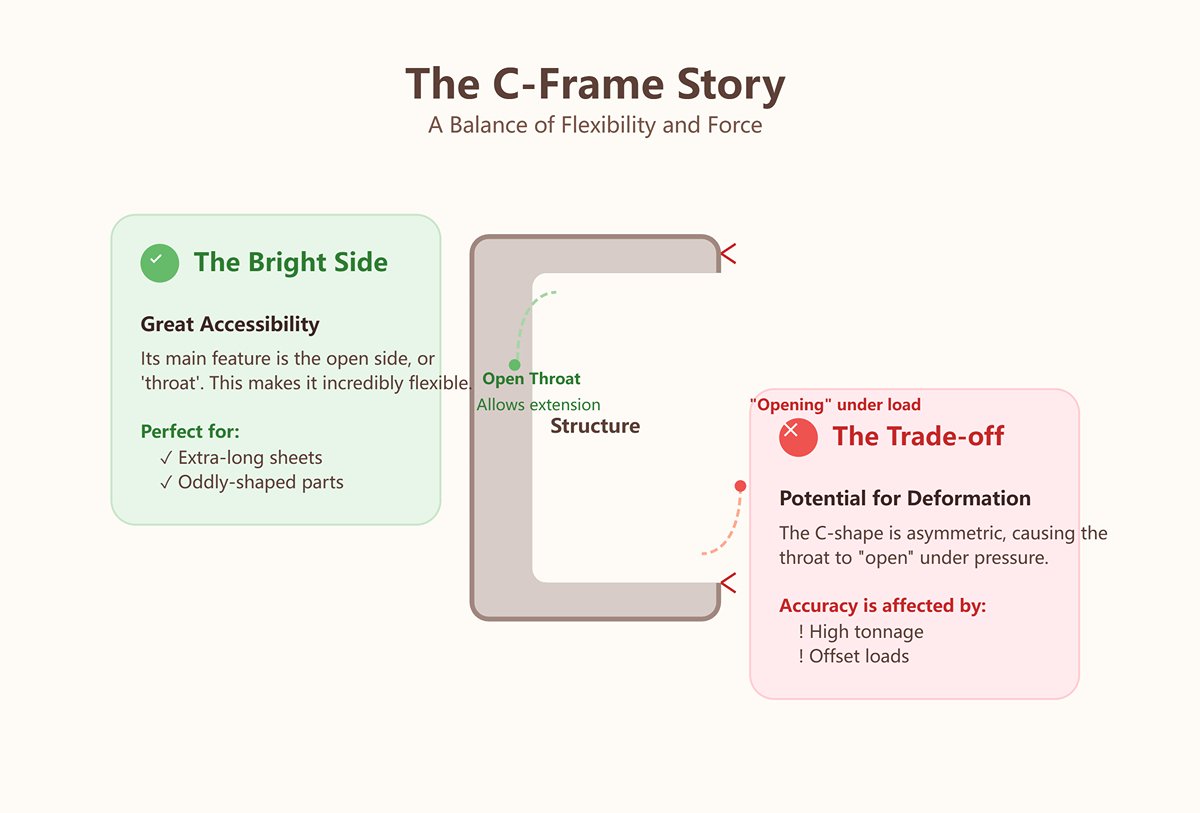
- Structural Features: The side plates of the machine form a “C” shape, with an open throat.
- Advantages: The key strength lies in its accessibility. When the sheet length exceeds the distance between the machine’s vertical columns, the material can extend out from the side, greatly enhancing flexibility—especially for extra-long or unusually shaped workpieces.
- Disadvantages: The inherent asymmetry of the structure means that under load, the throat inevitably experiences “opening” deformation. This affects bending accuracy, particularly when approaching maximum tonnage or performing offset loading, resulting in comparatively lower rigidity. For engineers comparing frame rigidity standards across different types of press brakes, ADH’s engineering documentation delivers extensive data references.
2.3.2 O-Frame (Box-Type): High Rigidity, Minimal Deformation, Stable Accuracy
- Structural Features: The frame is enclosed in an “O” shape or built as a fully welded box structure.
- Advantages: The enclosed design delivers unmatched rigidity. Under the same tonnage, its deformation under load is far less than that of a C-frame, providing an exceptionally stable reference for ram movement. This is the physical foundation for achieving high-precision, repeatable bends.
- Disadvantages: The closed sides sacrifice accessibility, making it impossible to process workpieces that exceed the machine’s width.
III. Decision Matrix: Building Your Ultimate Selection Framework
3.1 Key Performance Metrics Side-by-Side
Information overload is the enemy of sound decision-making. This table distills all core technology paths into a high-level “strategic map,” allowing you to grasp the big picture in five minutes and swiftly complete your first round of filtering.
| Performance Metric | Mechanical | Hydraulic (Torsion Bar) | Electro-Hydraulic Servo | Servo Electric | Hybrid |
|---|---|---|---|---|---|
| Accuracy/Repeatability | ★☆☆☆☆ | ★★☆☆☆ | ★★★★☆ | ★★★★★ | ★★★★☆ |
| Speed (Cycles/Min) | ★★★★★ | ★★★☆☆ | ★★★★☆ | ★★★★☆ | ★★★★☆ |
| Flexibility/Versatility | ★☆☆☆☆ | ★★★★☆ | ★★★★★ | ★★★☆☆ | ★★★★☆ |
| Energy Efficiency | ★★☆☆☆ | ★☆☆☆☆ | ★★★☆☆ | ★★★★★ | ★★★★☆ |
| Maintenance Complexity | ★★★★☆ | ★★☆☆☆ | ★★★☆☆ | ★★★★★ | ★★★☆☆ |
| Initial Investment | ★★★★★ | ★★★★☆ | ★★★☆☆ | ★☆☆☆☆ | ★★☆☆☆ |
| Tonnage Range | ★★★☆☆ | ★★★★★ | ★★★★★ | ★★☆☆☆ | ★★★★☆ |
(Scoring Guide: More stars indicate better performance; for Initial Investment, more stars mean lower cost)
Deep Dive: The Business Logic Behind the Ratings
Star ratings are just the outcome; understanding the reasons and implications behind them is essential for making truly informed decisions.
- The Micron-Level Accuracy Battle: The five-star accuracy of servo-electric press brakes (★★★★★) is no marketing exaggeration. Their fully closed-loop servo motors deliver positioning precision consistently within the 1-micron (±0.001 mm) range. This is an order-of-magnitude leap over high-quality electro-hydraulic servos, which hold to within 10 microns (±0.01 mm). When producing aerospace components, precision instrument housings, or premium electronic enclosures, that 9-micron gap is the difference between passing inspection and scrapping a part—often determining whether you win or lose a contract.
- The Cycle Time Illusion: Mechanical press brakes appear to boast the fastest stroke speed (★★★★★), but this can be misleading. True production efficiency is measured by the “total cycle time per part” (from material pickup to finished placement). Fixed stroke lengths can make mechanical machines slower in practice when complex back gauge positioning or multi-step bends are required, as auxiliary time offsets their speed advantage. In contrast, servo-electric and electro-hydraulic servos, with lightning-fast acceleration/deceleration and rapid back gauge adjustments, often outperform in real-world parts-per-hour output, becoming the true champions of productivity.
- The Hidden Cost of Energy Use: Traditional hydraulic press brakes (★☆☆☆☆) can be silent budget killers in the workshop. Even at idle, their pumps must run continuously to maintain system pressure. Servo-electric (★★★★★) and hybrid systems (★★★★☆), on the other hand, follow an “on-demand power” principle, consuming energy only during ram movement. Over years of operation, the energy savings can be substantial—directly boosting operating profits and serving as a decisive factor in the machine’s total cost of ownership (TCO).
3.2 Scenario-Based Optimization: The Best Choice for Specific Needs
If the previous section was your “satellite map,” then this chapter serves as the “GPS navigation” tailored to your specific business. Identify the scenario that best matches your production environment and follow the corresponding technical pathway.
| Production Scenario | Optimal Choice | Secondary Option | In-Depth Analysis |
|---|---|---|---|
| High precision, thin sheets, intricate small parts (e.g., electronics, medical devices, precision sheet metal) | Servo-electric | Electro-hydraulic | In this arena, precision reigns supreme. The unmatched repeatability of servo-electric systems, coupled with their immunity to hydraulic oil temperature drift and ultra-stable performance in a clean environment, make them the definitive choice. |
| High-volume, simple shapes, thick plate (e.g., structural steel, heavy machinery) | Electro-hydraulic (high tonnage) | Hydraulic (torsion bar) | The mission here is clear: deliver consistent output. High-tonnage electro-hydraulic machines provide immense power while outclassing torsion bar models in accuracy, flexibility, and energy efficiency—forming the backbone of modern heavy industry. |
| Multi-variety, small-batch, mixed thickness (general fabrication shops, contract manufacturers) | Electro-hydraulic | Hybrid | This is the ultimate test of equipment versatility. Electro-hydraulic systems, with their broad tonnage range, powerful CNC control, and adaptable processes, are true “all-rounders” capable of handling the most variable workloads with ease. |
| Extreme energy efficiency and low maintenance (automated lines, green factories) | Servo-electric | Hybrid | When operational costs (OPEX) outweigh capital expenditure (CAPEX), servo-electric is the ultimate answer. It eliminates hydraulic system issues—such as leaks, oil changes, and cooling—achieving the lowest TCO. |
| Ultra-tight budget startups | Hydraulic (torsion bar or basic CNC) | Second-hand mechanical | Initial investment is the primary concern. These machines offer the fastest route to building production capability at the lowest entry cost. However, decision-makers must recognize they are trading future efficiency and lower operating costs for immediate survival. |
3.3 Material and Thickness Matching Guide: Pair Your Workpiece with the Ideal Partner
Every selection process begins with the sheet in your hands. Choosing the right equipment and process for a specific workpiece is the foundation of quality, efficiency, and safety.
Step 1: Calculate Required Tonnage Scientifically
This is the most unforgiving calculation in the selection process. Too little tonnage, and you can’t form the part; too much, and you waste vast amounts of energy and capital. Use an online tonnage calculator or apply the proven formula below (for air bending at 90°):
- P: Required nominal force (tons)
- S: Material tensile strength (N/mm²)
- L: Bend length (mm)
- t: Material thickness (mm)
- V: V-die opening width (mm)
A priceless industry rule of thumb – the “8× principle”:
For common low-carbon steel (tensile strength around 450 N/mm²), the ideal V-die opening (V) is eight times the material thickness (t), i.e., V ≈ 8 × t. This golden ratio strikes the perfect balance between forming force, bend radius, and springback control. Adjust the factor for different materials: stainless steel’s higher toughness calls for V ≈ 10 × t, while softer aluminum alloys can be reduced to V ≈ 6 × t.
Step 2: Match Technology to Material Characteristics
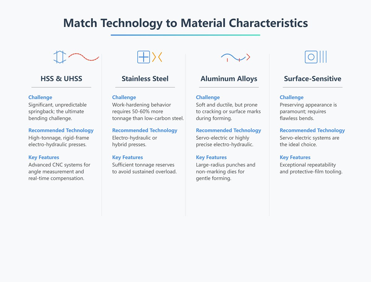
- High Strength Steel (HSS) & Ultra High Strength Steel (UHSS): These materials exhibit significant, unpredictable springback—posing the ultimate bending challenge. Opt for high-tonnage, rigid-frame electro-hydraulic presses with CNC systems capable of advanced angle measurement and real-time compensation to tame these “steel beasts.”
- Stainless Steel: Its work-hardening behavior requires roughly 50–60% more tonnage than low-carbon steel of the same thickness. Choose electro-hydraulic or hybrid presses with sufficient tonnage reserves to avoid sustained overload.
- Aluminum Alloys: Soft and ductile, but prone to cracking along the bend’s outer surface or leaving surface marks. Prioritize servo-electric or highly precise electro-hydraulic systems, paired with large-radius punches and non-marking dies for gentle forming.
- Surface-sensitive materials (e.g., brushed, mirror-polished, color-coated): Preserving appearance is paramount. Alongside protective-film tooling, the machine’s repeatability must be exceptional—servo-electric systems are the ideal choice for flawless bends every time.
IV. Real-World Selection: The Five-Step Method to Choose Your Ideal Press Brake
If the first three chapters provided a comprehensive technical map of press brake options, this chapter is your personal navigation tool. It takes you from theory to the decision-making front line, using a structured, actionable five-step method to turn understanding into investment precision. This isn’t just a checklist—it’s a decision-making framework to cut through market noise, avoid common procurement pitfalls, and pinpoint the machine that will deliver maximum value.
4.1 Step One: Define Your Needs Precisely—Break Down Your Core Tasks
Every selection process starts with a ruthless self-assessment. The costliest machine isn’t the one with the highest price tag—it’s the one least suited to your needs. Do your internal “due diligence” before speaking to any supplier.
1. Workpiece Profile Boundaries: Define Your Battlefield
- Material and Strength: What materials do you most frequently process—low-carbon steel, stainless steel, aluminum alloys, or high-strength steel? List their thickness range (from thinnest to thickest) and tensile strength. This directly determines your tonnage baseline.
- Size and Shape: What are the maximum length and width of the sheet you need to work with? Do your parts have extremely short flanges (which set limits on the backgauge and die)? Do you produce deep U-shaped boxes (testing throat depth and punch height)?
- Precision and Finish: How strict are your angle tolerance requirements (e.g., ±1° or ±0.3°)? Can you tolerate surface marks? Do you produce mirror-polished, brushed, or color-coated parts that are highly sensitive to cosmetic defects?
Expert Insight: The “Toughest Nut to Crack” Principle
When conducting a needs analysis, always identify the single most challenging workpiece in your product lineup. Take its most extreme specifications—thickest material, smallest internal radius, shortest flange—as the baseline for equipment selection. These three limits will physically define the boundaries of the machine platform, tooling system, and control capabilities you require. If your setup can handle that part, you’ll be well-equipped to tackle 99% of all other jobs.
2. Production Rhythm & Organizational Model: Define Your “Tactics”
- Batch Size & Changeovers: Is your production model high-mix, low-volume (HMLV), or low-mix, high-volume? How many die changes per day do you expect? Are quick-change tooling and offline programming just nice-to-have features, or mission-critical for survival?
- Automation Outlook: Do you plan to integrate robotic loading/unloading in the future? Should the machine interface with automated warehouses or AGV trolleys for data exchange?
- Workforce & Skills: Would you like the machine to capture and parameterize the expertise of seasoned technicians, reducing reliance on operator skill? How valuable would an intelligent system be with a built-in material library and automatic springback compensation algorithms?
3. Physical & Compliance Constraints: Define Your “Battleground”
- Space & Power: Does your workshop’s available footprint, foundation load capacity, and overhead crane lifting height meet equipment requirements? Is your electrical capacity sufficient? Are there specific cleanliness or low-noise standards to meet?
- Safety & Compliance: What safety standards must your facility comply with? Basic light curtain protection or advanced laser-follow systems?
4.2 Step Two: Scientific Parameter Calculation — The Golden Rule of Tonnage and Length
This is the most objective and unforgiving step in the selection process. Accurate calculation is the foundation of sound decision-making.
1. Core Formula: Air Bending Tonnage Estimation
For the most common air bending process (about 90% of applications), you can use the industry-recognized approximate formula below to estimate required tonnage:
T ≈ (K * L * t²) / V
- T: Required nominal force (tonnage, tons)
- L: Bend length (meters, m)
- t: Material thickness (millimeters, mm)
- V: V-die opening width (millimeters, mm)
- K: Material factor (empirical constant). Typically, mild steel = 1.33, stainless steel = 2.0, soft aluminum = 0.67.
2. Industry Rules of Thumb: V-Opening & Internal Radius
- V-opening Selection: Ideal V-opening (V) is 6–10 times the material thickness. A golden rule is V ≈ 8 × t. For stainless steel, increase to 10–12×; for aluminum, reduce to 5–6×.
- Internal Radius (R): In air bending, the internal bend radius is roughly 15–17% of the V-opening width. When V = 8t, the internal radius is about 1.3t.
- Minimum Flange Length: The shortest straight edge (flange) after bending must be greater than half the V-opening width; otherwise, the sheet will drop into the die, causing bending failure.
3. Quick Verification Example
Suppose you need to bend a mild steel sheet 3 m long and 4 mm thick.
- Step 1: Choose V-opening: V = 8 × t = 8 × 4 = 32 mm.
- Step 2: Apply formula: T ≈ (1.33 × 3m × 4²mm) / 32mm ≈ 1.995 × 10 ≈ 199.5 kN. Converted to tonnage ≈ 200 tons (1 ton ≈ 9.81 kN).
- Step 3: Factor in safety margin: In practice, allow 20–30% extra capacity for variations in material hardness, narrower V-openings, or bottoming bends. In this case, select a press brake of at least 240 tons.
Expert Warning: The Overlooked “Tonnage per Meter”
A common and dangerous oversight is focusing only on total tonnage while ignoring “pressure per unit length.” When using a narrow V-opening to bend a short section of thick plate, total tonnage may seem modest, but localized pressure on the tooling and machine could exceed design limits. Always confirm the machine’s “maximum tonnage per meter” rating—this is the key metric for local load-bearing capacity.
4.3 Step Three: Look Beyond the Price Tag — Analyzing Total Cost of Ownership (TCO)
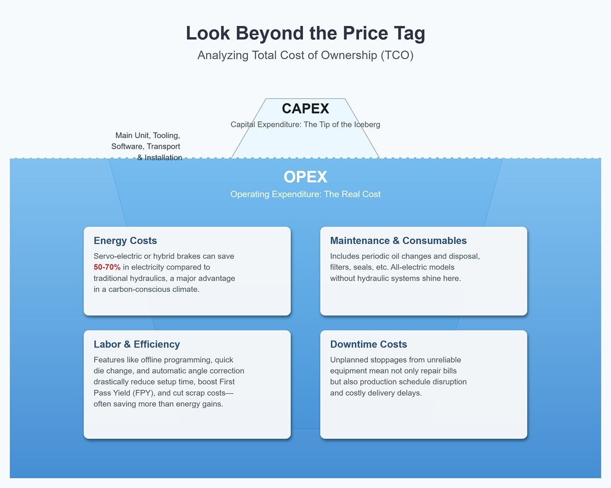
Shifting focus from purchase price to Total Cost of Ownership (TCO) is what separates amateurs from seasoned decision-makers. The real cost of a machine is the sum of all expenditures over its entire service life.
- Capital Expenditure (CAPEX): Just the tip of the iceberg, covering the main unit, tooling, software, and transport/installation.
- Operating Expenditure (OPEX): The submerged part of the iceberg—and the key to long-term profitability.
- Energy Costs: Servo-electric or electro-hydraulic hybrid brakes can save 50–70% in electricity during standby or light-load conditions compared to traditional hydraulics—a major advantage in today’s carbon-conscious climate.
- Maintenance & Consumables: Includes periodic oil changes and disposal, filters, seals, etc. All-electric models without hydraulic systems shine here.
- Labor & Efficiency: Features like offline programming, quick die change, and automatic angle correction drastically reduce skilled technician setup time, boost First Pass Yield (FPY), and cut scrap costs—often saving more than energy efficiency gains.
- Downtime Costs: Unplanned stoppages from unreliable equipment mean not only repair bills but also production schedule disruption and costly delivery delays.
Underrated but High-Value Insight: Rethinking ROI
For high-mix, low-volume workshops, the highest ROI often comes not from cutting-edge robotic cells, but from a combination of quick-change tooling + multi-axis backgauge + offline programming software. This setup minimizes non-productive auxiliary time, boosting Overall Equipment Effectiveness (OEE) and delivering payback in record time.
4.4 Step Four: Dig Into Core Configurations — The Key Variables Defining Final Performance
The devil is in the details. Two press brakes with identical tonnage and length can differ drastically in performance, precision, and lifespan. These are the core configurations you must scrutinize:
- Axis Configuration (The Brain’s Extension):
- Basic Axes: Y1/Y2 (independent control of left and right hydraulic cylinders) are standard in electro-hydraulic servo systems, ensuring synchronized ram movement.
- Core Backgauge Axes: X-axis (front/back) + R-axis (up/down) form the base configuration of modern press brakes.
- Advanced Axes: Z1/Z2 (independent left/right finger movement) greatly improve efficiency when producing asymmetrical or complex parts. More complex axes such as Delta X enable specialized processing like conical bends.
- Deflection Compensation System (The Backbone Support):
- Whether mechanical (via wedge blocks) or hydraulic (via cylinders), a precise, automatic deflection compensation system provides the physical foundation for maintaining consistent angles across the full length of long workpieces. This is the “soul” of any high-precision press brake.
- CNC Controller (The Intelligent Brain):
- A top-tier controller should offer graphical touchscreen programming, 3D model import, automatic bend sequence calculation, collision simulation, and a comprehensive built-in database for materials and tooling. This shifts complex process planning from the human mind to the computer, delivering true “what you see is what you get” operation.
- Tool Clamping System (Flexible Hands):
- Hydraulic or pneumatic quick-clamping systems replace traditional manual screw locks, cutting tool changeover time from half an hour to just a few minutes—critical for agile production.
- Safety System (Guardian of Life):
- From basic light curtain protection to more advanced laser-follow safety systems (which allow full-speed movement during the fast approach phase), safety features directly influence both operational efficiency and regulatory compliance.
A Commonly Overlooked Factor: Backgauge “Dynamic Performance” Many buyers focus only on the number of backgauge axes, overlooking acceleration and rigidity. A slow, heavy backgauge—even with many axes—will bottleneck multi-step bending cycles. Always check its positioning speed and repeatability specifications.
4.5 Step Five: Planning for the Future—Ensuring Your Investment Stays Relevant for the Next 5 Years
The equipment you purchase today is your ammunition for market competition over the next five years. Your decision must therefore be forward-looking.
- Technical Upgrade Headroom: Choose an open, modular platform. Ensure the machine is pre-configured with hardware ports and software protocols for future integration of robotic interfaces, angle measurement systems, and vision positioning systems.
- Flexibility in Process Capability: Can the system continuously capture and store expert know-how into its database? Can its control system adapt to new materials and processes through software updates?
- Data Connectivity Potential: Does it support standard industrial IoT protocols (such as OPC-UA, MTConnect)? Can it easily integrate with your factory’s MES or ERP systems for transparent data management and remote monitoring?
- Sustainability and Compliance: In light of tightening environmental (ESG) standards, prioritize energy-efficient, low-noise systems with no risk of hydraulic oil leakage—such as servo-electric or hybrid drive technologies—especially for clean industries like medical, food, and electronics.
- Service and Ecosystem: Opt for a brand with a strong market reputation, reliable spare parts supply, and a robust service network. An active user community and mature third-party tooling ecosystem often add more value than the machine alone.
By following this five-step approach, you’ll shift from being a passive price-taker to an active value-seeker. Your decisions will be driven not by gut feel or fragmented information, but by a deep understanding of your needs, the technology’s essence, financial models, and future trends. That’s the only real path to a successful investment.
V. Conclusion
In the end, a press brake is not just another machine on the factory floor—it's the engine of your productivity and a cornerstone of your product quality. We've journeyed through the different types of press brakes, uncovering how drive systems, control technologies, and frame structures dictate performance.
By following the five-step selection process, you are now equipped to look beyond the specs and identify the machine that truly aligns with your strategic goals, from materials and applications to long-term costs and future growth. Let's Build Your Competitive Edge Together.
Your ideal press brake is out there, and ADH has the expertise to help you find it. You can begin exploring our comprehensive range and detailed specifications in our Brochures. Our team has decades of experience guiding manufacturers to the perfect bending solution that balances performance, budget, and future-readiness. Don't leave your most critical investment to chance.
Contact us now for a personalized consultation, and let our ADH sales team help you configure the ultimate press brake for your needs.


