I. Finger Brake Overview
1.1 What Is a Finger Brake
A finger brake, also known as a box and pan brake, is a versatile machine which is applied in the fabrication of sheet metal. It uses adjustable fingers or clamping bars to bend and fold metal sheets into various shapes and angles accurately. It offers high precision and applies widely in industries such as automotive and construction.
Ⅱ. Breaking the Ice: Why a Finger Brake Is Your Essential Tool
In the vast world of sheet metal fabrication, countless tools vie for attention, yet few can match the Finger Brake (Box and Pan Brake) for its unique ability to strike the perfect balance between flexibility and cost-efficiency. It’s not just a bending tool—it’s a “spatial magician” designed to solve geometric challenges that stump conventional equipment. If you’ve ever struggled to make a metal box with multiple flanges or wrestled with the conflict between high-precision complex forming and a tight budget, this chapter will show you why the Finger Brake deserves a permanent place in your workshop arsenal.
2.1 Core Definition: Understand the Finger Brake in One Minute
The Finger Brake, also known as a Box and Pan Brake, is a precision sheet metal bending machine specifically engineered for producing metal boxes, chassis, and complex panels with multiple adjacent vertical sides.
- Function Overview: Picture fabricating an open-top metal box. You need to bend all four sides, but by the time you fold the third, a standard brake’s clamping beam collides with the first bent side. The Finger Brake was created precisely to eliminate this interference.
- Key Feature: Its “superpower” lies in the row of removable, modular steel fingers mounted on the clamping beam. Like piano keys, these fingers come in varying widths and can be arranged or removed strategically to leave clearance for already-formed sides, enabling successive bends that ordinary straight brakes simply can’t achieve.
2.2 Value Proposition: Why It Outperforms Other Bending Solutions
Among the many bending machines available, the Finger Brake holds an irreplaceable position thanks to its distinctive blend of benefits tailored to specific applications.
- Unmatched Flexibility: This is the heart of the Finger Brake’s appeal. Whether you’re making complex structures with side flanges—such as electrical enclosures, equipment housings, or metal trays—it’s the go-to choice. Its adaptable finger arrangement lets you bend around existing obstacles on a single sheet, transforming a flat panel into a precise three-dimensional form. It accomplishes what a standard Straight Brake would deem “impossible.”
- Outstanding Cost Efficiency: Compared to the substantial investment required for a CNC Press Brake, the Finger Brake offers high-precision complex bending at a fraction of the purchase and maintenance cost. It opens the door for small workshops, prototyping teams, DIY enthusiasts, and startups to access advanced forming capabilities without breaking the bank—a smart investment for maximizing manufacturing potential.
- Gentle Learning Curve: Operating a Finger Brake is intuitive, more akin to a hands-on conversation with physics and geometry than mastering programming and complex CNC setups. Manual adjustments make it easy to learn quickly, making it an ideal platform for nurturing craftsmanship and responding promptly to custom requirements.
For readers who want to explore how a press brake compares in capabilities and structure, check out Press Brake vs Pan Brake: Key Differences.
2.3 Key Decision: Finger Brake vs. Press Brake vs. Straight Brake
Choosing the right tool is half the battle in project success. To clear up any uncertainty, here’s the ultimate decision guide to define the boundaries between these three main bending machines.
- Function Boundary Comparison Table
| Feature | Finger Brake (Box and Pan Brake) | Press Brake | Straight Brake |
|---|---|---|---|
| Core Function | Produces boxes, pans, and other complex polygonal structures. | Performs high-precision, high-volume straight-line bends on metal sheets of varying thickness. | Performs simple long straight bends on thin sheet metal. |
| Structural Feature | Clamping beam made of removable, configurable fingers. | Uses upper punch and lower V-die for press forming. | Has a single, continuous clamping beam. |
| Flexibility | Very high—can easily bend around preformed sides. | Moderate—die changes allow various angles but closed boxes are difficult. | Low—limited to straight bends without clearance for obstacles. |
| Suitable Material Thickness | Best for medium to thin sheet (e.g., 1.0–3.0 mm steel). | Very wide range—from thin sheet to heavy plate, depending on tonnage. | Typically for thin sheets (e.g., under 1.5 mm). |
| Efficiency & Precision | Ideal for small-batch and prototyping—good precision. | Extremely high repeat accuracy and efficiency—built for mass production. | High efficiency for simple bends—precision depends on operator skill. |
| Cost | Low—economic choice for small shops and hobbyists. | Very high—heavy industrial investment. | Low—entry-level equipment. |
- Quick Selection Decision Matrix
Answer these questions, and the right machine will reveal itself:
What is your core product?
- Is it metal boxes, equipment housings, chassis, or pans with multiple flanges? → The Finger Brake is your top choice.
- Is it high-volume, uniform-angle parts, or thick steel plate bends? → You need a Press Brake.
- Is it just simple flashing, ductwork, or metal edging? → A Straight Brake will do the job most economically.
What are your production volume and budget plans?
- Small batches, varied designs, prototyping, tight budget? → The Finger Brake offers the best balance of flexibility and cost.
- Large-scale, standardized production, chasing ultimate efficiency, ample budget? → Invest in a CNC Press Brake for maximum returns.
- Key Application Scenarios at a Glance
- Finger Brake (Box and Pan Brake): Custom electrical control boxes, server cabinets, medical equipment housings, lab instrument chassis, custom panels for automotive restoration, drone frames, and any prototype requiring precise three-dimensional structures.
- Press Brake: The workhorse of industrial manufacturing. From automotive chassis and construction machinery arms to power transmission tower components, large architectural curtain wall panels, and appliance casings like refrigerator doors and washing machine frames—this machine dominates any application requiring high tonnage and precision.
- Straight Brake: Primarily serves the construction and light industry sectors. Common uses include HVAC ductwork, metal flashing for roofs, trim for doors and windows, and simple shelving or metal frames.
Ⅲ. Components and Accessories
3.1 Role of Finger Brake Dies
In a finger brake (also known as a box and pan brake), finger brake tooling is used to generate bends in specific areas of a workpiece, such as a metal sheet, without affecting the rest of the workpiece.
The "fingers" are movable blocks that can be adjusted to accommodate different sizes and shapes of workpieces.
When you need to perform a bend, you place the metal sheet on top of the fingers, arranging the fingers to match the desired bend. Then, the clamping bar descends, securing the workpiece in place.
Next, the bending blade (essentially a flat part located underneath the workpiece) is raised, causing the metal around the fingers to bend.
The key function of finger brake tooling is to achieve precise and intricate bends, which is particularly useful in creating boxes, pans, or other objects with specific shapes.
3.2 Types of Finger Brake Dies
A finger brake has different types of tooling, including V-dies, U-dies, hemming dies, and radius dies. Each type has a specific shape and purpose, allowing for a variety of bending possibilities.
- V-dies are commonly used and have a V-shaped groove that creates sharp bends in the metal.
- U-dies have a U-shaped groove and are suitable for making flanges or bending tubes with a slot.
- Hemming dies are designed for folding and overlapping metal edges, often used for seams or joining two pieces of metal together.
- Radius dies have a curved bending surface and are used to create bends with a specific radius. They are ideal for applications that require smooth, rounded bends.
3.3 Importance of Proper Tool Selection for Specific Applications
Choosing the appropriate tooling is crucial for achieving precise and desired bends. The selection depends on factors such as material type, thickness, required bending angle, and bending radius.
Different tooling options have varying levels of precision, allowing for flexibility in creating different shapes and angles.
Understanding the characteristics of different tooling and their compatibility with specific materials helps optimize the bending process, resulting in high-quality and consistent bends.
3.4 Contents of Finger Brake Kit
A "finger brake kit" usually includes a variety of tools and components that are designed to be used with a press brake for the purpose of bending sheet metal.
The exact contents can vary based on the specific kit and manufacturer, but commonly, these kits may include:
Finger Dies: These are the main components of the kit and come in a variety of sizes to accommodate different bend lengths. They are shaped to allow for the bending of specific sections of a workpiece without affecting other areas.
Mounting Hardware: This includes bolts, nuts, and other fasteners required to secure the dies and clamping bars to the press brake.
Adjustment Tools: These may include wrenches or other tools used to adjust the position of the finger dies or clamping bars.
Storage Case: Many kits also come with a case or box for storing and transporting the components.
User Manual: Instructions on how to safely and effectively use the finger brake dies and other components in the kit.
Press Brake Body: This is the main structure that supports the tooling and applies the force necessary for bending.
Lower Die or Bending Die: This is the lower tooling element that the sheet metal is pressed against
Support Equipment: Depending on the complexity of the kit, it might include additional equipment such as:
Back Gauges: These are positioning tools that help ensure the workpiece is aligned properly for precise bends.
Side Gauges: These help ensure that the workpiece is square to the bending line.
Clamping Tools: These tools are used to hold the workpiece securely in place during bending.
3.5 Frame and Structure
- Material and Construction: The frame is typically made of heavy-duty steel or welded steel plate construction to provide the rigidity and durability needed for repeated use under load. This robust design minimizes deflection and ensures consistent bending angles, even when working with thicker materials.
- Truss Rods and Braces: Many finger brakes include additional truss rods and braces to enhance structural stability during operation, especially for larger models.
3.6 Clamping Mechanism
- Purpose: The clamping mechanism secures the sheet metal in place during bending, preventing movement or slippage that could compromise the accuracy of the bend.
- Operation: The clamping bar is manually or mechanically adjusted to tightly hold the workpiece against the lower die or worktable. This ensures precise alignment before bending begins.
- Adjustability: Some models feature quick-setting nose bars or tensioner bolts for fine-tuning the clamping pressure, allowing operators to accommodate different material thicknesses easily.
3.7 Forming Rod and Apron
- Forming Rod: This component helps achieve specific bend angles by guiding the sheet metal during the bending process. It is particularly useful for creating consistent bends across long sheets.
- Apron (or Bending Leaf):
- The apron is manually lifted to bend the sheet metal around the fingers or forming a rod.
- Equipped with features like adjustable counterbalances or stop rods for repeatable bends, the apron ensures smooth operation even during heavy-duty tasks.
Ⅳ. In-Depth Analysis: Understanding the Finger Brake’s Operating Principles and Performance Limits
To truly master a Finger Brake, one must go beyond basic operation and delve into its mechanical core—grasping the purpose of every bolt and the reasoning behind every counterweight. While the design may appear straightforward, it is, in reality, a precise orchestration of mechanics, geometry, and ergonomics within a confined space. This chapter will dissect this “spatial magician,” revealing the intricate logic behind its operation and the boundaries of its capabilities.
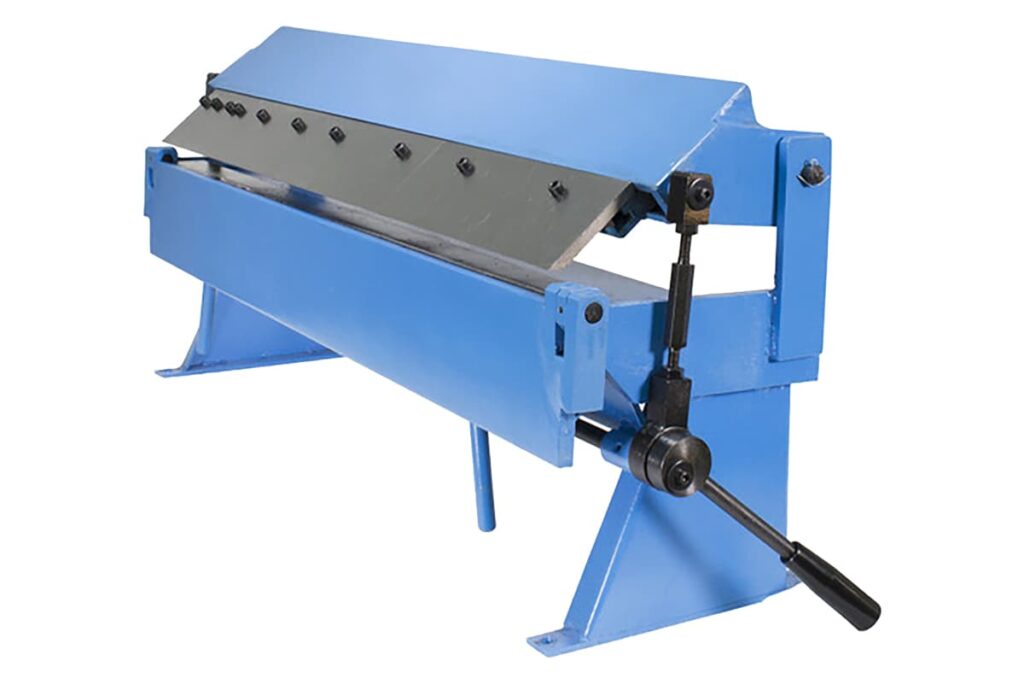
4.1 Mechanical Anatomy: One Diagram to Understand All Core Components
A high-performance Finger Brake is the culmination of multiple systems working seamlessly together. The following is a detailed breakdown of its core components, accompanied by a structural diagram to give you instant insight into its inner workings.
- The Foundation of Stability: The Source of All Precision
- Body and Base: Serving as the machine’s skeleton, these parts are typically constructed from heavy cast iron or high-rigidity steel plates welded together. They provide a rock-solid platform for all moving components, while their mass and stiffness counteract the immense reactive forces generated during bending. A machine that wobbles can never produce accurate workpieces.
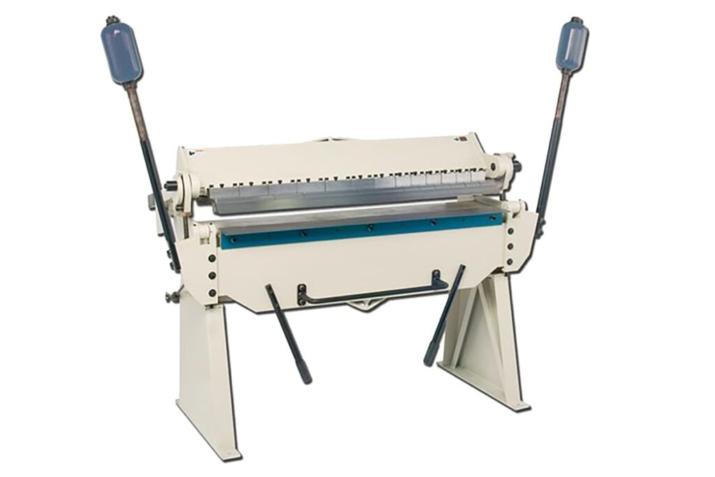
- Counterweights: Suspended behind the bending apron, these adjustable weights are a hallmark of operator-friendly design. Using leverage, they precisely offset the apron’s considerable mass, allowing the operator to lift it smoothly with minimal effort. This reduces physical strain and enables finer control during bending.
- Clamping Core: Where Power Meets Precision
- Clamping Beam: Positioned above the machine body, this movable component is driven by a long side handle. It exerts powerful vertical pressure to firmly hold the sheet metal in place against the body, ensuring absolute immobility during bending.
- Fingers: The heart of the Finger Brake. These are a series of individually removable, high-strength steel modules mounted along the clamping beam’s front edge, available in various widths. With just a few bolts, they can be installed, removed, or rearranged. This modular ingenuity gives the machine the ability to “work around” pre-formed obstacles, overcoming the geometric limitations of conventional brakes.
- Execution Unit: The Creator of Angles
- Bending Apron: A flat, movable structure located at the lower front of the machine, rotating upward around a precise pivot. Once the sheet is secured, lifting the apron pushes the protruding section of the sheet along the lower edge of the fingers, inducing a controlled plastic deformation to achieve the desired angle.
- Precision Assurance: From “Close Enough” to “Perfectly Consistent”
- Clamping Pressure Adjustment: By fine-tuning the truss rods located on either side or at the rear of the clamping beam, operators can adjust the clamping force. This is essential for accommodating materials of varying thickness and hardness—strong enough to prevent slippage, yet gentle enough to avoid marring softer metals like aluminum or copper.
- Angle Stop: Typically an adjustable bolt or block positioned along the bending apron’s rotation path. Setting it in advance ensures each bend stops precisely at the target angle (e.g., 90°), providing consistent results in batch production.
- Backstop / Back Gauge: A movable ruler system mounted at the rear of the machine. Positioning the sheet’s trailing edge against the backstop allows for quick, repeatable alignment of bend lines, freeing the operator from constant re-measuring and greatly increasing efficiency and accuracy.
4.2 Operating Mechanism: How Sheet Metal Is Formed with Magical Precision
The Finger Brake’s operation is a simple yet elegant display of mechanical principles. Understanding this sequence is the first step toward mastering its use.
- The Three-Step Physical Process: Clamp → Bend → Release
- Clamping: Place the marked sheet between the machine body and the fingers on the clamping beam. Use the backstop or align with the scribed line for accurate positioning. Operate the clamping handle to lower the beam, locking the sheet in place under tons of pressure.
- Bending: Grip the bending apron handles with both hands and lift steadily in one continuous motion. The apron bends the sheet along the lower edge of the fingers, pivoting until it meets the preset angle stop. Consistent, even force is key.
- Releasing: Return the apron to its starting position, then reverse the clamping handle to raise the beam and remove the finished workpiece.

- The Secret of the Fingers: Solving 3D Geometric Challenges — this is where the Finger Brake’s true “magic” lies. Let’s take the example of forming a standard five-sided (open-top) metal box:
- First Bend: With no obstructions, use any combination of fingers as long as their combined width exceeds the workpiece.
- Second Bend (Adjacent Side): The first 90° bend now stands upright, interfering physically with the clamping beam. Simply remove the finger(s) that correspond to the length and position of this upright edge, creating a gap for clearance. This allows the sheet to be reinserted and clamped for the second bend.
- Continue in Sequence: By continuously analyzing upcoming interference and strategically adjusting finger placement, all four sides can be bent in turn—transforming a flat sheet into a precise three-dimensional box. The ability to plan finger configurations is the hallmark of an expert operator.
- The Secret of Bend Radius: A Key Detail Defining Finish Quality — The inner rounded edge of the bend, known as the bend radius, is not random. It is primarily determined by two factors:
- Shape of the Finger Block’s Leading Edge: The sharper the leading edge, the smaller the resulting bend radius—approaching a right angle. Conversely, a rounded leading edge produces a larger bend radius. This is why the quality of the finger block is so critical.
- Gap Between the Bending Beam and the Clamping Beam: Before bending, adjust the gap between the bending beam and the upper clamping beam so it is slightly larger than the material’s thickness. This gap allows space for the material to stretch and compress during bending. If the gap is too small, the material may be overly compressed or even sheared; too large, and the bend radius becomes unpredictable and angles inaccurate.
4.3 Performance Decoding: Understanding Key Specifications and Material Compatibility
Knowing the performance limits of a Finger Brake is essential for safe operation and maximizing its potential. Understanding these specifications before purchasing can help you avoid costly mistakes.
- Key Performance Metrics:
- Maximum Bending Length: The widest sheet the machine can bend in a single operation, commonly 48 inches (1220 mm) or 72 inches (1830 mm).
- Maximum Material Thickness / Capacity: Perhaps the most critical specification, usually expressed in gauge or millimeters (mm) and rated for a specific material—often mild steel. Professional insight: This rating typically assumes short bend widths under ideal conditions. When bending at full length, actual capacity often drops by one gauge level.
- Maximum Bending Angle: Most Finger Brakes can bend from 0° to 135°, sufficient for nearly all box and enclosure fabrication needs.
- Throat Depth: The distance from the finger block’s front edge to the rear of the clamping beam assembly. Greater throat depth allows for bending larger sheets without interference from the machine frame.
- Quick Material Compatibility Guide: The Immutable Laws of Physics
| Material Type | Thickness Limit Characteristics | Springback Behavior | Professional Advice |
|---|---|---|---|
| Mild Steel | Baseline material for machine’s rated thickness. | Moderate springback. Requires slight over-bending (e.g., bend to 92° to achieve 90°). | The most common material; machines are designed for it. |
| Stainless Steel | Very high hardness. Requires far greater bending force than mild steel. Rated thickness usually must be reduced by at least 4 gauges (e.g., 16ga steel → 20ga stainless). | Significant springback; precise calculation and greater over-bend are necessary. | Causes substantial machine wear. Avoid sustained full-capacity bending of stainless to prevent permanent damage. |
| Aluminum | Soft material; bends easily at the same thickness, allowing rated thickness to be slightly relaxed. | Low springback; easy to form but prone to cracking. | Avoid excessive clamping force to prevent surface marring; use protective film. |
| Copper/Brass | Similar to aluminum: very soft with excellent ductility. | Minimal springback. | Highly prone to surface scratches—clean finger blocks and machine surfaces before operation. |
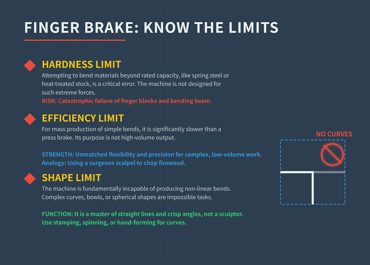
- Common Misconceptions: Busting the “Finger Brake Can Do Anything” Myth Believing a Finger Brake is all-powerful is one of the most dangerous mistakes beginners make. Always respect its limits:
- Hardness Limit: It is absolutely unsuitable for materials exceeding rated thickness—especially high-hardness sheets like spring steel, high-strength alloy steel, or any heat-treated stock. Forcing such bends will not only ruin the workpiece but may deform the bending beam, fracture the finger blocks, and cause irreversible damage to the machine.
- Efficiency Limit: For thousands of simple straight bends, its speed is far inferior to a press brake. The Finger Brake’s true value lies in its unmatched flexibility, not in raw production speed. Using it for straightforward mass production is like using a chef's knife to chop firewood.
- Shape Limit: Despite its versatility, it cannot produce complex curves (e.g., bowl shapes, spheres) or non-linear bends. Those tasks belong to stamping, spinning, or traditional sheet metal hand-forming. The Finger Brake excels at straight lines and angles—it is not a sculptor of curves.
Ⅴ. How to Use a Finger Brake
Step 1: Place the Sheet on the Lower Die
- Begin by positioning the sheet metal on the lower die (also referred to as the worktable). The edge of the sheet should align with the desired bending line, which is typically marked beforehand using a scribe or marker.
- Ensure that the sheet is flat and properly seated to prevent uneven bends.
Step 2: Adjust Fingers to Match Desired Bends
- Arrange the adjustable fingers on the clamping bar according to the shape and width of the bend you want to create:
- Remove unused fingers or reposition them to avoid interference with adjacent sections of the sheet.
- For complex shapes like boxes or pans, leave gaps between fingers to accommodate multiple bends.
- Secure the fingers in place by tightening thumbscrews or bolts, ensuring they are firmly locked to avoid shifting during operation.
- Adjust finger height if necessary to achieve specific bend radii, especially for thicker materials.
Step 3: Operate the Clamping Bar
- Lower the clamping bar using its handle or lever to secure the sheet metal firmly in place. This step is critical for preventing slippage during bending.
- Adjust clamping pressure based on material thickness:
- For thin sheets, reduce pressure to avoid deformation.
- For thicker sheets, increase pressure for a tighter grip.
Step 4: Bend the Sheet Using the Apron
- Grab both handles of the apron (bending leaf) and lift it upward to bend the sheet metal around the fingers:
- Apply even force on both handles to maintain consistent bending angles across the entire length of the sheet.
- Stop lifting once you reach your desired angle. Most finger brakes can create bends up to 135 degrees, but this may vary depending on the model and material.
- If necessary, perform additional adjustments or repeat this step to refine the angle.
Step 5: Release and Inspect
- Lower the apron back into its original position carefully. Avoid sudden movements that could damage either the machine or your workpiece.
- Raise the clamping bar and remove your bent sheet metal.
- Inspect your workpiece for accuracy:
- Check that angles match your specifications using a protractor or angle gauge.
- Verify that edges are clean and free from distortions.
Additional Considerations
- Sequential Bends: For projects requiring multiple bends (e.g., boxes), repeat steps 1–5 for each bend while ensuring proper alignment after each operation.
- Material-Specific Adjustments:
- For softer metals like aluminum, use lighter clamping pressure and slower bending movements to avoid over-bending.
- For harder metals like stainless steel, ensure proper lubrication of moving parts and apply greater force during bending.
Safety Tips
- Keep hands clear of pinch points under clamping bars and around moving parts.
- Use appropriate Personal Protective Equipment (PPE) such as gloves and safety glasses to protect against sharp edges and debris.
- Familiarize yourself with emergency stop buttons and ensure they are accessible before starting operations.
Ⅵ. Finger Brake Safety Guidelines
When using a finger brake, safety is of paramount importance. These machines are powerful tools used for bending metal sheets, and it is crucial to understand their safety features and take appropriate preventive measures to prevent accidents and injuries.
In the following section, we will explore various common safety features of finger brake and discuss important preventive measures to ensure safe operations.
Safety Features
1. Emergency Stop Button: finger brakes are equipped with easily accessible emergency stop buttons that can immediately halt the machine's operation in case of an emergency or potential danger. Operators should familiarize themselves with the location of these buttons and receive training to react quickly when needed.
2. Safety Interlocks: Many finger brakes are equipped with safety interlock systems that prevent the machine from running when safety guards or doors are open. This feature ensures that operators cannot accidentally start the machine while in unsafe positions or during maintenance work.
3. Protective Shields and Guards: finger brakes typically come with protective shields and guards to safeguard operators from potential hazards such as flying debris or contact with moving parts. It is crucial not to bypass or remove these protective devices as they play a vital role in preventing injuries.
Preventive Measures
1. Proper Training: Operators should undergo comprehensive training on finger brake operation, safety procedures, and emergency protocols. They should be familiar with the machine's user manual. They should become acquainted with the machine's control devices, understand their limitations, and receive training to identify and address potential risks.
2. Personal Protective Equipment (PPE): Operators must wear appropriate PPE, including safety glasses, gloves, ear protectors (if necessary), and safety shoes. PPE helps prevent injuries from sharp edges, flying debris, and excessive noise generated during the bending process.
3. Machine Inspection: Before operation, ensure that the machine is in good working condition. Check for secure power connections and ensure that all components are in good condition.
4. Proper Parameter Settings: Set the machine's bending angle, pressure, speed, and other parameters correctly based on the desired bending angle and material thickness.
5. Preparations Before Processing: Before processing, ensure that the worktable is clean and tidy, and the material is securely fixed to prevent accidental movement or slipping during the machining process.
6. Maintain Focus During Operation: Stay focused during operation, avoiding distractions or negligence that can lead to accidents.
7. Follow Proper Operating Procedures: Follow the correct procedures for operation, keeping hands away from moving parts of the machine to prevent crushing or other injuries.
8. Cleanliness Before Shutdown: After completing the job, promptly clean the worktable and machine, properly store materials and tools, and ensure that the machine is in a safe state.
Regular maintenance, inspections, and adherence to safety guidelines ensure a safe working environment. By understanding the safety features and following necessary preventive measures, operators can significantly reduce the risk of accidents when using finger brake machines.
Ⅶ. Advanced Path: Breaking Through Limitations to Achieve Expert-Level Mastery
Once you’ve mastered the basics, you can produce workpieces that meet standard requirements. But to move from “acceptable” to “exceptional” and become a true sheet metal artisan, you must make a qualitative leap in accuracy, efficiency, and your ability to handle complex shapes. This chapter moves beyond the “how” to focus on the underlying “why,” revealing the core principles that distinguish novices from experts—helping you break through skill plateaus and enter a realm of creative freedom.
7.1 Advanced Techniques: Secrets for Greater Precision, Efficiency, and Complex Forming
These are the guarded techniques of professional workshops—methods that will challenge your assumptions and equip you to solve unconventional problems.
- Strategies for Complex Geometries:
- Precision in U- and C-Channel Forming: The main difficulty in bending U-channels is that the second bend often collapses inward, throwing off the channel width. The expert solution is to use a Sacrificial Block. Before making the second bend, clamp a metal block whose thickness precisely matches the intended inner width of the channel along with the workpiece. This block acts as a rigid internal support, forcing the second bend to form tightly against it, ensuring perfectly parallel inner walls and dimensional accuracy.
- Smart Execution of Multiple Offsets/Joggles: When making Z-shaped or stepped offset bends with very close bend lines, standard methods can easily tear the material. Instead of investing in costly dedicated Offset Dies, a clever alternative is step-by-step forming. First, make a shallow initial bend along the first line (around 45°); then flip the workpiece and make a shallow reverse bend immediately adjacent; finally, re-clamp and press each bend to its final angle. This gradual deformation gives the metal time to adjust and stretch, significantly reducing stress concentration.
- Sequence Rules for Unequal Flange Heights in Box Construction: When box flanges vary in height, the bending order can make or break the build. Golden rule: always bend the tallest, longest flange first. This flange will intrude most into the workspace, so once it’s up, all subsequent bends must be made in a much more restricted area. Tackling this “biggest obstacle” first maximizes your freedom for the remaining steps.
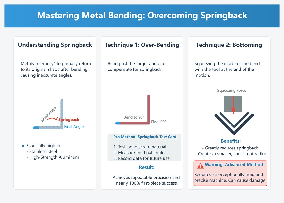
- Springback Compensation: A Deep Conversation with Metal
- Nature of Springback: Metal has “memory.” Once bent beyond its elastic limit, it undergoes permanent plastic deformation—but when the force is released, it will always try to recover part of its original shape. This phenomenon is called springback. It’s especially pronounced in stainless steel and high-strength aluminum alloys, and ignoring it means you’ll never achieve precise angles.
- Quantifying Over-Bending: The most direct way to counter springback is to “over-bend.” If your target angle is 90° and the material springs back 3°, you must bend to 93°. Guesswork is for amateurs—professionals aim for repeatable precision. A proven method is to create a springback test card: take a scrap piece and perform several precise test bends (e.g., set the angle stop to 91°, 92°, 93°, 94°), measure the final angle after springback with a high-precision protractor, and record the results. Build a set of such data cards for your most-used materials and thicknesses—this will push your first-piece pass rate close to 100%.
- The Art of Bottoming: On some high-rigidity finger brakes, you can fine-tune the final travel of the bending beam so that, at the end of the motion, the front edge of the fingers delivers a strong compressive “squeeze” to the inside of the bend. Known as “bottoming,” this greatly reduces springback and produces a smaller, more consistent bend radius.
- Warning: This is an advanced technique requiring exceptional machine rigidity and precision. Attempting bottoming on insufficiently rigid equipment can cause permanent damage.
- Special Edge Treatments: Elevating Function and Aesthetics
- Two-Step Standard for Hemming: Hemming folds a metal edge completely over itself, creating a safe, strong, and aesthetically smooth finish. On a finger brake, the industrial-grade two-step method is: First, make a narrow, large-angle pre-bend (industry standard is 135° or more); second, release the workpiece and adjust the clamping height (gap set precisely to twice the material thickness), reinsert the pre-bent edge, and instead of using the bending beam, apply vertical pressure from the clamping bar to flatten it completely.
- Simulated Stiffening Rib Pressing: Adding shallow grooves (stiffening ribs) to flat sheet metal greatly increases its structural strength. While typically done with a press, you can simulate this on a finger brake: Clamp a round steel rod of the right diameter—or a specially made round-tipped bar—together with the workpiece under the clamping bar, then slightly lift the bending beam to push a smooth groove into the sheet.
- Developing Operator ‘Feel’: The State of Human–Machine Unity
- Auditory Diagnostics: Learn to listen to your machine during clamping and bending. A steady, muted sound of metal deforming is a healthy sign; sharp squeaks or loud bangs may indicate excessive pressure, impending material failure, or loose machine parts.
- Visual Warning Signs: While bending, keep your eyes on the metal surface just outside the bend line. The appearance of fine “orange peel” texture means the material is being overstretched and is nearing its forming limit—this is the final warning before cracking.
- Tactile Feedback: Use the handle to sense changes in resistance during the bending process. Smooth, steadily increasing resistance is the ideal scenario. A sudden spike in resistance could indicate unexpected interference or variations in material thickness. An experienced operator can often judge the smoothness of a bend purely by feel and make adjustments before a problem escalates.
7.2 Efficiency Optimization: Transitioning from Single-Piece Work to Batch Production
Efficiency is another benchmark of professional skill. When an order scales from one piece to a hundred, your entire approach must shift accordingly.
- Workflow Design: Using Process to Conquer Chaos
- Batch Processing Mindset: This is the first step from craft-level work toward industrial-scale production. Never complete all processes on a single part before moving to the next. The correct approach is: perform the first bend on the entire batch; then reset the machine and complete the second bend for all parts, and so on. This batch process drastically minimizes time lost to repeated machine setups.
- "Left In, Right Out" Flow Planning: Stack raw sheets neatly on the left side of the machine, and place finished parts in order on the right. This creates a smooth, one-way material flow, eliminating unnecessary shuffling and turning. In batch production, even the smallest movement optimizations accumulate into significant time savings.
- Tooling and Fixtures: Empowering Speed and Precision
- Custom Positioning Stops: Beyond the machine’s built-in back gauge, irregular shapes or parts needing multi-point alignment can be accommodated using strong magnets or small G-clamps to secure steel blocks to the frame as temporary reference points. These homemade foolproof fixtures make placing complex workpieces an instinctive, error-free task.
- Angle Templates: For repeated non-standard bend angles, it’s more efficient to bend a precise sample from scrap material and fix it to the side of the machine as a physical reference, rather than relying on an angle gauge every time. During operation, simply raise the bending beam until it aligns with the template—clear and fast.
- Best Practices in Batch Bending: Minimizing Finger Block Changes When planning a batch bending sequence, a critical goal is to reduce the number of finger block swaps and rearrangements. Before starting, analyze all bend steps to group operations that can use the same or similar block setups. For example, if an order includes two box sizes, complete all the smaller boxes using one setup before switching to the larger box configuration. This is far more efficient than alternating between the two sizes.
7.3 In-Depth Case Studies: Real-World Challenges and Solutions
Theory reaches its true value only when it solves real problems. The following two cases show how experts apply systematic thinking to overcome challenges that seem impossible at first glance.
- Case One: Custom High-End Audio Amplifier Chassis
- Challenge: The front panel has pre-punched decorative louvers for ventilation and embossed studs for circuit board mounting, all created by CNC punching before bending. During forming, these delicate features must be avoided entirely—any flattening or damage means scrapping an expensive part.
- Expert-Level Solution:
- Virtual Folding and Interference Analysis: The first step happens on a computer, not in the shop. Use CAD software to simulate the bend precisely, identifying where pre-made features might physically interfere with the press brake’s fingers.
- Finger Block "Cut-Out" Strategy: For fingers that would intrude on louvers or embosses, don’t simply remove them (which would reduce clamping force). Instead, machine precise relief grooves into the fingers at the interference points using a mill or handheld grinder. These task-specific custom fingers are the ultimate problem solver.
- Segmented, Selective Clamping: For especially complex panels, abandon the idea of clamping along the entire line. Use multiple narrow fingers, intentionally leaving gaps above sensitive features (such as louvers) and applying clamping force only to flat, load-bearing areas—like performing surgical precision work.
- Case Two: Replicating Wheel Arch Panels in Classic Car Restoration
- Challenge: Accurately reproducing a vintage car’s wheel arch panel, which has a graceful, large-radius curve rather than a sharp angle. A finger brake excels at straight lines—so how do you make it “draw” a curve?
- Expert-Level Solution: This calls for a master-level artisan technique—Segment Bending (also known as Bump Bending)—using countless small straight bends to closely approximate a curve.
- Create a Physical Radius Template: Based on the original panel or design drawings, make a full-scale template of the required curvature from plywood or acrylic. This serves as your guiding reference throughout the process.
- Dense Marking: On the sheet to be bent, mark a series of very closely spaced, parallel bend lines (for example, every 3–6 mm depending on the curve’s radius).
- Continuous "Micro-Angle" Bending: Along each marked line, make an extremely small bend (typically 1–2 degrees). By repeating these micro-bends densely, the resulting straight segments visually merge into a smooth, natural curve.
- Ongoing Comparison and Fine-Tuning: This is a hands-on, visually guided process. After every few bends, compare the workpiece to the physical template, adjusting angles and positions as needed. It demands patience and spatial awareness—representing the pinnacle of manual skill and experience.
Ⅷ. Future Challenges and Solutions
With the continuous development of the manufacturing industry and technological advancements, finger brakes are also facing several challenges:
Challenge 1: High precision requirements
As product designs become increasingly complex, the precision requirements for bending parts are also becoming higher.
Traditional finger brakes may encounter accuracy issues when handling intricate curves and small-sized components.
Solution:
Adopt advanced CNC systems: Implementing advanced CNC systems can provide more precise bending control and data processing, thereby achieving higher precision requirements.
Utilize high-precision tooling: Choosing high-precision tooling can ensure better bending quality and accuracy, meeting design requirements.
Challenge 2: Handling diverse shapes
As product diversity and personalized demands increase, finger brakes need to be able to handle a wider range of workpiece shapes, including complex curves, irregular shapes, and three-dimensional components.
Solution:
Introduce multi-axis control: Employing multi-axis control systems enables more complex bending operations to meet the demands of different workpiece shapes.
Utilize adjustable tooling: Opting for adjustable tooling systems allows for flexible adaptation to different workpiece shapes, while providing higher processing efficiency.
Challenge 3: Automation and intelligence requirements
With the development of industrial automation and smart manufacturing, users have increasingly higher expectations regarding the automation and intelligence levels of finger brakes. Traditional manual operation modes may not meet these requirements.
Solution:
Automated backgauge system: Implementing an automated backgauge system enables automatic workpiece positioning and backgauge adjustment, thereby improving production efficiency and consistency.
Intelligent control system: Utilizing intelligent control systems enables data analysis and real-time monitoring, providing more efficient production management and fault diagnosis.

Challenge 4: Sustainable development and environmental protection
In the current global context of environmental protection, traditional finger brakes may face issues such as high energy consumption and excessive waste generation, which do not align with sustainable development requirements.
Solution:
Energy-saving design: Optimizing mechanical structures to reduce energy consumption, for example, by incorporating efficient servo drive systems and intelligent energy management technologies.
Waste management: Strengthening waste classification and recycling efforts to minimize environmental impact.
When facing future challenges, finger brakes need to continuously adapt and innovate.
By incorporating advanced CNC systems, multi-axis control, automation and intelligence technologies, as well as solutions focused on energy efficiency and environmental protection, finger brakes can better meet the demands for high precision, diversity, automation, and sustainable development.
This will provide the manufacturing industry with more efficient, flexible, and sustainable sheet metal processing solutions.
Ⅸ. Key Factors and Important Considerations in Choosing the Finger Brake
Important Factors
- Capacity Requirements: First and foremost, you need to determine your capacity requirements. Based on your production volume and workpiece size, choose a finger brake that is suitable for your needs.
- Different machine models and specifications have different capacities and adaptability. Ensure that the machine you choose can meet your expected capacity.
- Price and Budget: Price is also a key factor. Based on your budget, choose a machine that is reasonably priced.
- Please note that the price is often related to the machine's configuration, brand, and manufacturer.
- Make sure that the quotes you receive offer a reasonable value for money and compare them with multiple suppliers.
- Technological Features and Innovations: Consider the technological features and innovations of the finger brake. Some advanced finger brakes are equipped with advanced CNC systems, multi-axis controls, automation, and intelligent features to improve production efficiency and processing quality. Determine if you need these features and choose the appropriate model based on your requirements.
- Reputation of Brand and Manufacturer: It is crucial to choose a reputable brand and manufacturer of sheet metal box pan brake. Well-known brands usually have better quality control and after-sales service, providing more reliable machines and technical support.
Before Making a Purchase, Follow These Steps:
- Conduct Testing: Arrange for testing and demonstrations of the machine before making a purchase.
- This will help you understand the machine's performance, ease of operation, and bending quality.
- Consult Professionals: Seek advice and opinions from professionals such as bend machine operators, process engineers, or sales representatives. They can provide practical experience and insights on different brands and models.
- Remember, purchasing a sheet metal finger brake is a significant investment decision. Choosing the right model and supplier will provide you with high-quality machines and comprehensive after-sales support.
ADH is a professional sheet metal machinery manufacturer with 20 years of experience. The press brake is our flagship product. We also provide shear, laser cutting, panel bender, etc., and we can help you choose the right press brake and provide robust after-sales support. If you need information about our press brake, please contact our sales staff or browse our press brake product page.
Ⅹ. FAQs
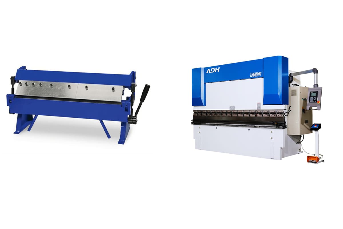
1. How does a finger brake differ from a press brake?
| Feature | Finger Brake | Press Brake |
| Precision | ±0.1 mm, High for intricate designs | ±0.01 mm, Higher for large-scale uniform bends |
| Maximum Bending Force | Up to 50 tons, suitable for thinner materials (maximum thickness 6.35mm) | Up to 3000 tons, suitable for heavy materials (e.g., steel plates over 20mm thick) |
| Worktable Length | 2 feet to 12 feet | 4 feet to 14 feet |
| Bending Angle Range | 0° to 135° | 0° to 180° |
| Operation | Manual or semi-manual | Often automated (hydraulic/CNC) |
| Speed | Up to 10 bends per minute | Up to 20 bends per minute |
| Portability | Lightweight (200 kg to 2 tons), easy to move and install | Heavy (1 ton to 50 tons), usually fixed installation |
| Applications | Custom work, small-scale production | Industrial-scale manufacturing |
| Cost | Lower upfront investment | Higher due to advanced technology |
| Energy Requirements | Uses single-phase power (110V/220V), lower energy consumption | Uses three-phase power (220V/380V), higher energy consumption |
A finger brake differs from a press brake in that it is primarily used for creating intricate shapes with multiple bends and flanges, such as boxes and pans, through manually adjustable fingers. It is ideal for smaller-scale, custom projects and lighter materials.
Conversely, a press brake is more suited for heavy-duty tasks, offering high precision and automation with CNC controls, making it capable of handling thicker materials and large-scale production. Press brakes are designed for more complex bending operations and consistent batch production, while finger brakes excel in versatility and ease of use for custom and prototype work.
2. How do you maintain a finger brake?
To maintain a finger brake, regularly clean the machine to remove dust and debris, lubricate moving parts, and inspect for wear and tear, replacing any damaged components immediately. Ensure proper alignment of the fingers and dies, tighten loose parts, and check hydraulic fluid levels and electrical connections for models that require it.
Calibrate the machine periodically for precision, inspect safety features, and store the brake in a dry, clean environment. Follow the manufacturer's maintenance schedule, which includes daily, weekly, and annual tasks, to keep the finger brake operating safely and efficiently.
XI. Conclusion
A finger brake is a specialized tool used for bending metal, with its adjustable finger allowing for precise bending of different sizes.
Its advantages over other methods include flexibility and accuracy, making it useful in diverse applications like manufacturing and construction.
The hydraulic version further enhances power. Essential components include the dies that determine the bend shape. The kit usually contains various accessories for versatile operations.
Using a heavy duty finger brake requires an understanding of the mechanics and safety precautions to prevent accidents. Ultimately, a finger brake is an indispensable tool for anyone involved in metalworking.