"How big of a press brake do I need?" It's a critical question for any fabrication shop, where the right answer drives efficiency and profit. While it's tempting to focus only on tonnage and length, this approach often leads to costly mistakes and underperformance. A truly optimal decision requires a deeper understanding of the machine's core capabilities.
This guide cuts through the confusion. We'll dismantle common sizing myths, show you how to calculate tonnage accurately, and provide a practical, four-step method to select your ideal machine. By moving from basic needs to advanced strategies, you'll learn how to choose a press brake that not only works, but excels—powering your shop's growth for years to come.
I. Dispelling the Fog: Building the Right Framework for Understanding Press Brake Size
The moment you type “What size press brake do I need?” into a search bar, you’ve already stepped into a subtle but dangerous mental trap. Your mind may instinctively reduce “size” to two cold, simplistic numbers: tonnage and length.
But making a potentially six- or seven-figure investment based on this two-dimensional view is like sailing through dense fog—it’s far too easy to run aground. True professional machine selection begins with a complete upgrade in how you think about the problem. To explore real-world examples and technical insights, visit ADH Machine Tool, a trusted manufacturer offering comprehensive press brake solutions.
1.1 Decoding “Size”: More Than Just Length and Tonnage—It’s the Combination of Three Core Capabilities
A press brake that delivers maximum value isn’t defined by a flat, two-dimensional concept of size. Instead, it’s a three-dimensional cube built from three core capabilities. Neglecting any one dimension can leave your production constrained or your costs spiraling out of control.
- Force (Tonnage): The machine’s muscle. This is the maximum pressure a press brake can exert, measured in tonnes. Like a weightlifter’s strength, it directly determines the thickness and strength of the materials you can bend. The force needed to bend a 3 mm sheet of high-strength, wear-resistant steel is worlds apart from that required for the same thickness of ordinary aluminum. This is the most basic parameter—and also the one most often misunderstood. For a deeper understanding of tonnage calculation, check out how big of a press brake do I need.
- Length: The machine’s reach: This includes both the bed length and, more critically, the distance between housings. It defines the maximum width of workpieces you can handle. But this is not simply a “longer is better” equation—an oversized frame can eat up precious floor space and compromise precision and efficiency for smaller parts. For an extreme look at scale and engineering, explore The World’s Largest Press Brake to understand how industrial design pushes boundaries while balancing performance.
- Precision & Control: The machine’s brain and nervous system. Often overlooked, this dimension determines final product quality and production speed. It covers the number and accuracy of backgauge axes, the level of synchronization between cylinders, the effectiveness of crowning systems, and the intelligence of the CNC controller. Force and Length define what you can do; Precision & Control determines how well, how fast, and how consistently you can do it. This is the dividing line between a mediocre machine and a true productivity powerhouse.
So, erase the word “size” from your mental vocabulary and replace it with a three-dimensional concept of “overall capability.” This is the first—and most crucial—step toward making the right decision.
1.2 The Selection Pyramid: Understanding the Priority of the Three Key Metrics
These three capabilities are not equal in importance; they follow a strict hierarchy I call the Selection Pyramid. Getting the order wrong will lead directly to the wrong conclusion.
1. Base Layer: Core Processing Needs (Materials & Parts) — The foundation of the pyramid and the starting point for all decisions. Before touching any machine specs, you must scrutinize your products like a detective:
- Material & Thickness: What materials do you process most often—carbon steel, stainless steel, aluminum? What is the range of thicknesses—thinnest and thickest?
- Workpiece Dimensions & Shapes: What are the lengths of your largest and smallest parts? Do you have complex shapes that need to pass through from the side (challenging the distance between housings)?
- Precision Requirements: Are you producing standard box structures or aerospace components requiring tight angular tolerances?
This layer allows no compromise or vagueness—it determines the stability of your entire selection framework.
2. Middle Layer: Matching Precision and Efficiency — Based on your core needs, match the machine’s “brain and nervous system” accordingly.
- If your parts are simple and produced in high volumes, a fast, stable basic CNC system with high-precision X and R-axis backgauges may be sufficient.
- If your parts are complex and require precision within ±0.5°, multi-axis backgauges (X, R, Z1, Z2) and advanced hydraulic or mechanical crowning systems become essential.
This layer determines your return on investment. The right choices here will keep adding value year after year by reducing scrap rates and boosting throughput.
3. Top Layer: Calculating Tonnage & Length — Only after the first two layers are clearly defined do we reach the top of the pyramid: determining final tonnage and length. At this stage, they are no longer guesses—they are precise results based on material, thickness, bend radius, V-die opening, and workpiece length. For accurate tonnage and bending force calculation, refer to how big of a press brake do I need. These are the end points of the decision, not the starting points.
1.3 Fatal Misconception: “Bigger is Better” is the Most Expensive Lie
“Buy bigger, just in case.” — This seemingly wise advice is, in the press brake world, an extraordinarily costly fallacy. You think you’re buying future potential, but in reality you’re paying upfront for present-day problems.
Opting for a machine far beyond your needs means:
- Sky-high initial investment: Every extra inch of length and every extra tonne of force burns through your budget.
- Runaway operating costs: Larger motors and hydraulic systems drive up your electricity bills—like running a heavy truck in stop-and-go city traffic, fuel consumption is excessive.
- Expensive tooling ecosystem: High-tonnage machines demand stronger, larger tooling systems, multiplying your tooling investment.
- Loss of precision and efficiency: This is the most dangerous. Using a 500-ton machine to bend 1 mm sheet metal is like using a cannon to kill a mosquito—slow to respond and unable to maintain precise force control at very low loads, leading to unstable bend angles and higher scrap rates.
- Permanent space consumption: Such a machine will permanently swallow valuable workshop area, limiting future line layout flexibility.
The smartest investment is a machine that perfectly covers 80% of your current core business, with a reasonable safety margin for the foreseeable 20% growth. Our goal is exact fit, not blind excess.
Now you have the right decision-making framework. Next, we’ll move to the practical stage: learning to scientifically calculate the size that truly suits your needs.

II. Core Principle: A Scientific Method for Accurately Calculating Required Tonnage
With a solid conceptual foundation in place, it’s time to master the single most decisive skill in this investment process: scientifically calculating the tonnage you actually need. To simplify the process, you can also explore digital guides such as how big of a press brake do I need. This isn’t a mysterious dark art—it’s rigorous science. Forget guesses and intuition; we’ll use an engineer’s precision and the logic of physics to pinpoint your one true number.
2.1 The Ultimate Breakdown of the Tonnage Calculation Formula
In sheet metal work, over 90% of bending operations use the Air Bending method, and the required tonnage follows a basic physical formula. At first glance, it may seem intimidating, but once broken down, you’ll see its logic is crystal clear.
A widely used metric-based simplified formula for low-carbon steel is as follows:
P (kN) = (650 × S² × L) / V
Let’s break it down piece by piece, much like dissecting a precision instrument:
- P (Pressure/Tonnage): This is the final value we’re after—the bending force required, expressed in kilonewtons (kN). To convert it into the more familiar unit of tons, simply divide the kN result by 9.8.
- S (Sheet Thickness): The thickness of the sheet, measured in millimeters (mm). This is the most impactful variable in the entire formula. Note that the required tonnage increases in proportion to the square of the thickness. In other words, if the thickness doubles from 2mm to 4mm, the tonnage doesn’t just double—it quadruples. This isn’t a linear rise; it’s an explosive exponential jump in force. Overlooking this is one of the most common mistakes when selecting equipment.
- L (Length): The length of the workpiece to be bent, measured in meters (m). This is a straightforward linear relationship—double the length, and the required tonnage doubles as well.
- V (V-Die Opening): The opening width of the lower V-die, measured in millimeters (mm). This is an inverse relationship: the smaller the V-die opening, the greater the tonnage required. It’s like using a shorter lever to lift a heavy load—you inevitably need more force. A well-established industry rule of thumb is to choose a V-die opening that is 8 to 10 times the sheet thickness. For example, for 3mm sheet metal, a V-die of 24mm (3mm × 8) or 30mm (3mm × 10) is ideal.
Critical Adjustment: The “Force Factor” for Different Materials
The constant “650” in the formula isn’t arbitrary—it’s an empirical coefficient based on mild steel with a tensile strength of roughly 450 MPa (such as China’s Q235). When working with metals of different “personalities,” you must adjust this coefficient. A simple way to do this is by scaling it according to the material’s tensile strength ratio:
- Stainless Steel (304): Tough and resilient, with much higher tensile strength than mild steel. Multiply the force factor by about 1.5, giving a value of ~1000.
- Aluminum Alloy (6061): Softer and more yielding. Multiply the force factor by about 0.5, giving a value of ~350.
Mastering this formula gives you the ability to independently and accurately assess tonnage requirements.
2.2 Interactive Tools: Your Digital Co-Pilot for Machine Selection
In the digital age, there’s no need to perform manual calculations every time. Nearly all major press brake manufacturers offer interactive tonnage calculators on their websites. Consider these tools your “digital co-pilot” for equipment selection, not just basic calculators.
Their real value lies in simulation and comparison. You simply enter a few key parameters:
- Material Type
- Thickness
- Bend Length
- V-Die Opening
Within moments, you’ll get an accurate tonnage estimate. More importantly, you can quickly run “What-If” scenarios: What happens if I switch from mild steel to stainless steel? or If I must use a smaller V-die for a tighter bend radius, how much will the tonnage increase? These tools turn complex calculations into clear decision-making insights, allowing you to approach discussions with suppliers fully prepared.
2.3 Common Material Tonnage Quick Reference: A Workshop Essential
For everyday production, a clear tonnage quick reference chart posted on the wall is worth as much as a hefty operation manual. It transforms complex calculations into an easy-to-read visual guide, serving as a shared language between supervisors and operators.
Here’s a simplified example chart showing the required tonnage per meter of bend length for mild steel (unit: tons/m):
| Sheet Thickness (mm) | V=8mm | V=12mm | V=16mm | V=24mm | V=32mm | V=40mm | V=50mm |
|---|---|---|---|---|---|---|---|
| 1.0 | 8 | 5 | 4 | ||||
| 2.0 | 21 | 16 | 10 | 8 | 6 | 5 | |
| 3.0 | 35 | 23 | 18 | 14 | 11 | ||
| 4.0 | 42 | 32 | 25 | 20 | |||
| 5.0 | 48 | 38 | 30 |
Note: This chart is a simplified example for illustration only. For actual use, always refer to the professional, detailed charts provided by your equipment supplier.
Using it is straightforward:
- Locate your material thickness on the left column.
- Find the V-die opening you plan to use along the top row.
- The intersection of these two values gives the tonnage required per meter of bend length.
- Multiply this value by the actual bend length of your workpiece (in meters) to get the total tonnage.
2.4 The Secret of Safety Margin: How Much Extra Tonnage Is Smart, Not Wasteful?
Once you’ve calculated the theoretical maximum tonnage, you face a crucial question: how much safety margin should you add? This impacts machine lifespan, long-term stability, and the efficiency of your investment.
The Golden Rule: The 20% Principle

A widely recognized and time-tested industry guideline is to add a 20% reserve to your calculated theoretical maximum tonnage. For instance, if your toughest job requires 80 tons, choosing a 100-ton press brake is both wise and economical. This extra 20% provides critical cushioning:
- Compensating for Material Variations: Even within the same batch, sheet metal can have slight differences in chemical composition and mechanical properties.
- Offsetting Tool Wear: Over time, die wear can subtly increase the bending force required.
- Protecting Machine Health: Any equipment running constantly at 100% load will suffer accelerated wear in its hydraulic system, seals, and frame. Operating at around 80% load greatly extends both accuracy and service life.
Professional Warning: Beware the “Centerline Load Limit”
This is a high-level technical point that buyers often overlook—and it can have catastrophic consequences. A press brake’s rated tonnage (say, 100 tons) refers to its ability to handle a load evenly distributed over a substantial portion of the bed—typically 60% or more of its total length.
However, if you need to bend a very thick plate over a very short length—say, applying 80 tons of force over just 200 mm—you may exceed the machine’s centerline load capacity. This concentrates immense force directly at the “waist” of the ram and worktable. Even if the total rated tonnage is not surpassed, such an extreme “tonnage density” can cause permanent plastic deformation in the ram or bed, destroying the machine’s precision.
Your machine’s manual will typically list a maximum allowable load per unit length, expressed as “tons per meter” or “tons per foot.” Before attempting any short, heavy bending operation, always verify this parameter. It is often more restrictive than the total tonnage rating.
By mastering the relevant formulas, leveraging digital tools, consulting practical charts, and fully understanding safety margins and load limits, you have elevated tonnage selection from an “art” to a precise “science.” Your decisions are no longer based on vague intuition, but grounded in solid data and logic.
III. Practical Methodology – Four Steps to Pinpoint Your Ideal Machine
We’ve mastered the science of calculating tonnage; now it’s time to turn those theoretical numbers into a tangible machine that stands in your workshop and generates value. This is not impulsive shopping—it’s a disciplined process of engineering alignment. I’m going to share a four-step method, proven in world-class factories, that serves as a precise battle plan to guide you through the maze of model selection and straight to your target.
3.1 Step One: Determine the Ideal Bed Length
Choosing the right machine length might seem like the simplest step—just make sure it’s longer than your longest workpiece. Yet this seemingly harmless assumption has led to countless procurement disasters where the dimensions were “technically sufficient” but the machine proved unusable.
Core Principle: Anchor to Your Primary Workpiece Start by using the size of your most common, longest workpiece as the reference point. For example, if your core business involves processing 2.5 m standard sheets, selecting a press brake with a 3.2 m (about 10.5 ft) bed is a sensible starting point. This gives you a comfortable margin for handling your standard parts.
Professional Warning: Beware the “Distance Between Housings” Trap Now, shift your focus from the brochure’s “overall length” to a parameter that truly determines success or failure: Distance Between Housings.
This is the clear span between the inner faces of the machine’s C-frame uprights. It represents the actual maximum width you can bend in a single pass. Think of it like the difference between the total length of a bridge and the clear span between its piers—a vessel wider than the gap cannot pass, no matter the bridge’s full length.
For example, a press brake advertised as 3.2 m long may have only 2.6 m between the housings. This means your 2.8 m “standard workpiece” cannot be bent in one pass through the middle. You would be forced into inefficient compromises such as multi-stage bending or side insertion, sacrificing both productivity and accuracy—or you might not be able to process the piece at all.
Action Tip: When comparing machines, treat “distance between housings” as equally important to “overall length.” It directly determines the maximum workpiece width you can process in one efficient operation.

3.2 Step Two: Match the Key Vertical Clearance Parameters
If length defines the machine’s “reach,” then three vertical parameters—together forming the “work window”—define the complexity of the workpiece geometries you can produce. Overlooking them could leave you with a press brake that can bend sheet metal but cannot produce finished products.
- Maximum Open Height (Daylight) This is the largest vertical gap between the upper tool holder and the bed when the ram is fully raised. Its importance goes far beyond fitting the tooling—it must allow you to safely remove the finished workpiece. For example, when making a box with a 200 mm high flange, the open height must exceed the sum of the upper tool height, lower tool height, and the 200 mm flange, plus at least 50 mm clearance for safe removal. Insufficient open height means your deep box will be trapped between the tools after the final bend, turning it into costly scrap.
- Stroke This is the maximum vertical travel of the ram. Adequate stroke ensures the upper tool can complete the bending motion and then lift high enough to adjust or remove the workpiece. Stroke and open height work together—a large open height paired with a very short stroke is like a tall door that only opens a crack, severely limiting usability.
- Throat Depth This is the horizontal distance from the bending centerline to the inner wall of the C-frame. Think of it as the machine’s “throat,” determining how far it can accommodate a sheet. When bending in the middle of a large sheet (such as a big enclosure panel), sufficient throat depth prevents the far end of the sheet from hitting the side frame. For many sheet-metal products, throat depth is the critical “pass” that determines feasibility.
Action Tip: Take the drawing of the most geometrically complex product you make. Measure its tallest flange and deepest profile. This drawing becomes your strongest negotiating tool when discussing these three vertical parameters with suppliers.
3.3 Step Three: Plan Physical Space and Infrastructure
This is the easiest step to overlook, yet it is often the source of “disasters” during installation. A press brake is not just a standalone block of steel—it is a system that must integrate seamlessly with its environment.
- Footprint and Dynamic Operating Space Planning goes far beyond the “length × width” footprint listed in the specifications. A professional layout must include the “dynamic operating zones”:
- Front and Rear Zones: Allow enough space for safely loading and unloading your longest sheets. A good rule of thumb is to reserve a straight-line distance in front and behind the machine equal to the length of your longest workpiece.
- Side Zones: Maintain at least 1 m clearance for hydraulic station servicing, electrical cabinet access, and operator movement.
A cramped layout is not only a safety hazard—it will also strangle production efficiency.
- Foundation Requirements: The Machine’s Lifeline Medium and high-tonnage press brakes demand extremely high standards for floor load capacity and levelness. The manufacturer’s technical manual will specify the required concrete foundation thickness, reinforcement details, and curing time. Neglecting proper foundation preparation can lead to calibration difficulties and long-term accuracy drift at best, or permanent frame deformation at worst. This upfront investment is an insurance policy for stable operation over the next decade.
- Power Supply: The Energy Lifeline Before signing the contract, have your electrician verify these critical points:
- Electrical: Almost all industrial press brakes require three-phase industrial power. Confirm that your workshop’s transformer capacity and voltage stability meet the specifications on the machine’s nameplate (for example, 380 V ± 5%).
- Compressed Air: Many modern quick-clamping systems, follower supports, or balancing mechanisms require clean, stable compressed air. Verify the required pressure (bar) and flow rate (L/min).
Action Tip: Before making your final decision, request the "Equipment Foundation Drawing" and "Pre-installation Preparation Manual" from the supplier. Take these documents to your workshop and conduct a thorough on-site “mock installation” with your engineers. This step alone can help you avoid at least 80% of unexpected issues and extra costs later on.
3.4 Step Four: Choose a Control System That Matches Your Production Rhythm
If the machine frame is its skeleton, and hydraulics are its muscles, then the CNC system is the “brain and soul.” It directly dictates your production efficiency, scrap rate, and how much you rely on operator experience. Pick the wrong “brain,” and even the strongest “body” will fail to win the efficiency race.
- Basic NC/CNC Systems: The Fixed-Takt Production Worker Best suited for highly repetitive, single-product, mass production. Operators must manually enter parameters such as bending angles and backgauge positions. Its main advantage is low cost, but it demands significant programming expertise and trial-bending skills from the operator. Every product change means lengthy adjustments. Ideal for scenarios where the same part is produced for years without variation.
- 2D Graphical CNC Systems: The Efficient Multi-skilled Technician Currently the mainstream and best value choice. Operators can draw a 2D cross-section of the workpiece directly on the touchscreen or import DXF files. The system automatically calculates bending sequences, backgauge movements, required pressure, and checks for collision risks. This dramatically reduces programming difficulty, cutting new product setup time from hours to minutes—an essential tool for “high mix, low volume” production.
- 3D Graphical CNC Systems: The Master Process Strategist Standard in high-end models, representing the pinnacle of bending intelligence. It allows direct import of 3D product models (such as STEP files) and runs dynamic simulations in a complete virtual environment including the machine, tooling, and workpiece. Operators can rehearse the entire process on-screen, eliminating any collision risks. For aerospace, precision medical devices, and other high-value, complex components, it ensures “first-piece perfection,” delivering returns far beyond its purchase price.
Action Tip: Don’t be dazzled by flashy interface demos. Bring the drawing of your most complex part (2D or 3D) to the supplier and ask them to program and simulate it on the spot. Watch for programming fluidity, the intelligence of automatic calculations, and error-prevention capabilities. Every dollar you invest in the machine’s “brain” should deliver tangible results in this step.
By following this logically rigorous four-step method, you’ve transformed a vague, overwhelming purchasing task into four clear, actionable units. You’re no longer a passive market spectator—you’ve become the professional architect of your own production needs.
IV. Advanced Strategies: From “Usable” to “Exceptional” Decision-Making
If you’ve completed the first three sections with us, congratulations—you now have all the knowledge needed to choose a press brake that is “fit for purpose.” Your decision will be grounded in data and logic, capable of avoiding 90% of common beginner mistakes.
But our mission goes further. The gap between a world-class factory and an ordinary workshop is often defined by this final step: moving from “usable” to “optimal,” and even “outstanding.” This is about maximizing long-term ROI, production flexibility, and future competitiveness. This section is where the line is drawn between a competent buyer and a strategic production visionary.
4.1 Technology Showdown: How Hydraulic, Electric, and Hybrid Drive Systems Shape Your Choice
The drive system is the heart of a press brake—it determines response speed, energy consumption, precision retention, and maintenance characteristics. Labeling these three technologies as simply “good” or “bad” is amateurish. Professional judgment lies in precisely matching them to your unique production rhythm and workpiece requirements.
Traditional Hydraulic Press Brake: The Heavy-Duty King

- Profile: Like a battle-tested heavy truck—immensely powerful, proven technology, and ready to tackle high tonnage and ultra-thick plates with ease. Supported by a global maintenance network.
- Best Use Case: Your core business involves processing plates over 6mm thick, workpieces several meters long, or occasional processes like coining or straightening that require extended holding pressure. For budget-conscious factories focused on heavy-duty work, it remains the most cost-effective choice.
- Hidden Costs: The hydraulic pump keeps running—even during idle loading/unloading—consuming electricity and generating heat. This shows up on your power bill and can cause oil temperature drift, affecting angle consistency in long production runs. Regular replacement of hydraulic oil, filters, and seals adds to long-term operating costs.
Servo Electric Press Brake: The High-Speed Precision Sprinter
- Profile: Comparable to an F1 race car—driven directly by servo motors through screws or belts, delivering lightning-fast response and repeat positioning accuracy down to the micron.
- Best Use Case: Ideal for “high mix, low volume” environments with frequent tooling and program changes. Primarily used for medium to thin sheets (typically under 130 tons capacity), where tight angle consistency and fast production cycles are critical. Clean and quiet, it’s perfect for medical, electronics, and other controlled environments.
- Key Insights:
- True Energy Advantage: Its breakthrough lies in “power on demand.” During idle time, the motors consume virtually no electricity. In high-changeover, high-speed workflows, total energy use is only 20–30% of an equivalent hydraulic machine.
- Speed Misconceptions: The electric drive's “speed” comes from its explosive acceleration and ultra-short response times, significantly reducing non-bending auxiliary time. Due to safety standards, its working descent speed is similar to modern hydraulics; its real value is in unmatched repeat precision and faster overall cycles.
- Sensitivity to Off-Center Loads: For concentrated loads on one side of the machine, electric models often have stricter protective limits. Always check the manufacturer’s “off-center load capacity curve.”
Servo Hybrid Press Brake: The All-Rounder
- Profile: Like a high-performance hybrid SUV—combining the energy-smart “power on demand” of servo motors with the muscle of hydraulics, using variable or servo pumps to drive hydraulic cylinders.
- Best Use Case: Perfect when you need both the tonnage for medium-thick plates and the energy efficiency and stability of electric systems. It slashes idle energy use and heat generation compared to traditional hydraulics, improves angle consistency, and retains the ability to handle heavy-duty tasks. It’s the ideal balance of performance, energy consumption, and cost.
- Trade-Offs: Greater system complexity demands higher diagnostic skills from after-sales service teams.
Expert Insight: Don’t ask “Which technology is best?”—ask “Which technology best fits my production profile?” The ultimate factor in consistent product angles is rarely the drive type alone, but rather a complete quality control system combining high-precision encoders, closed-loop control, and dynamic deflection compensation.
4.2 Future Framework: Designed for Growth, Not Just the Present
Buying a press brake is a decision that should look at least five to ten years ahead. The costliest mistake is realizing two years later that your “new” machine has already become a bottleneck for business expansion. Designing for the future is not about blindly chasing the biggest possible machine, but about strategically building in flexibility.
Step 1: Map Out Your “Demand Roadmap” Review your business plan for the next 3–5 years. Will new products use higher-strength materials? Will customers demand greater precision? Will workpiece size and complexity increase? Based on this, define the “core demand profile” (the tasks that make up 80% of your output) and allocate resources accordingly. Your choice should perfectly serve this “core frequency,” rather than buying an oversized machine that spends most of its life underutilized just to handle the rare 5% extreme cases.
Step 2: Invest in Scalability, Not Excess Tonnage Instead of wasting budget on an extra 20% tonnage you’ll never use, invest it in critical options that determine future efficiency and capability. Here’s your expansion priority list:
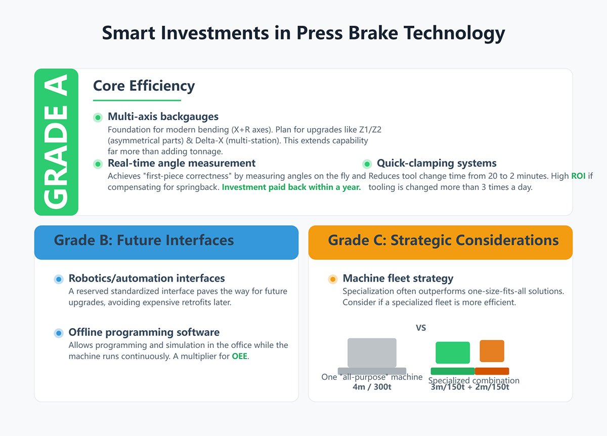
- Grade A (Core Efficiency):
- Multi-axis backgauges: X+R axes are the foundation of modern bending. Plan for the ability to upgrade to Z1/Z2 axes (for asymmetrical workpieces) and Delta-X axis (for multi-station bending). This extends your processing capabilities far more than adding tonnage.
- Real-time angle measurement systems: The ultimate tool for “first-piece correctness,” these systems measure bend angles on the fly and automatically compensate for springback, minimizing scrap. The value they generate often pays for the investment within a year.
- Hydraulic/pneumatic quick-clamping systems: Reduce tool change time from 20 minutes to just 2. If you change tooling more than three times a day, the ROI will surprise you.
- Grade B (Future Interfaces):
- Robotics/automation interfaces: Even if you have no immediate automation plans, a reserved standardized interface paves the way for upgrades later, avoiding expensive retrofits.
- Offline programming software: Allows engineers to complete all programming and simulation in the office while the machine runs continuously. This is a multiplier for Overall Equipment Effectiveness (OEE).
- Grade C (Strategic Considerations):
- Machine fleet strategy: Sometimes, the efficiency and cost of a single 4m, 300-ton “all-purpose” machine can’t match a combination of a 3m, 150-ton high-speed electric/hybrid (for thin sheets) plus a 2m, 150-ton economical hydraulic (for thick, small parts). Specialization often outperforms one-size-fits-all solutions.
4.3 Cost-Benefit Analysis: Calculating Your True Total Cost of Ownership (TCO)
Smart investors never focus solely on the price tag—they consider the asset’s full lifecycle value. The Total Cost of Ownership (TCO) model is like a scalpel that cuts through the superficial price to reveal the real costs and returns.
The TCO Iceberg Model:
- Above-water iceberg (Visible Costs – CapEx):
- Main machine purchase price
- Transport, installation, and foundation work costs
- Initial investment in tooling and quick clamps
- Software licenses and staff training
- Underwater giant (Hidden Costs – OpEx):
- Energy costs: (Idle power × standby hours) + (Loaded power × operating hours) × electricity price. For high-cycle production, electric/hybrid machines can save thousands to tens of thousands annually.
- Maintenance costs: Replacement of hydraulic oil, filters, seals, and labor.
- Productivity costs: Time and materials wasted during test bends and machine setup; scrap and rework costs due to inconsistent accuracy. This is often the largest and most overlooked part of TCO.
- Downtime risk costs: A critical failure can cause losses from delayed orders and penalty fees, costly emergency outsourcing, and intangible damage to brand reputation.
Quick ROI Calculation Template: Assume a high-spec machine (with angle measurement and quick clamps) costs ¥200,000 more than a basic hydraulic machine. Let’s calculate how quickly that premium pays for itself:
- Tool change savings: (15 minutes saved per change × 4 changes/day) ÷ 60 × 250 working days × ¥300/hour machine value = ¥50,000/year
- Quality improvement savings: (Scrap rate reduced from 3% to 0.5%) × ¥1,000,000 annual output value = ¥25,000/year
- Energy savings: (Hydraulic average power 5kW – hybrid average power 2kW) × 8 hours × 250 days × ¥1/kWh = ¥6,000/year
Annual total savings = 50,000 + 25,000 + 6,000 = ¥81,000 Payback period = ¥200,000 ÷ ¥81,000/year ≈ 2.47 years
A payback period under three years is an excellent investment for any industrial equipment. That ¥200,000 premium doesn’t look like a “cost” anymore—it’s a high-return investment.
4.4 Innovative Perspective: The “Tooling-Centered” Selection Method
This is a selection philosophy top-tier factories rarely share. The traditional approach is “machine to part”—choose the machine first, then see what parts it can produce. The tooling-centered method flips this entirely: “Part to tool, tool to machine.”
- Step 1: Focus on the end product and define core processes Forget the machine for now. Take the drawings of your most complex, highest value product. Analyze the smallest bend radius, shortest flange height, and most intricate geometric interferences. These parameters will dictate the type of V-die opening and the shape of gooseneck punches you need.
- Step 2: Build your “ideal tooling library” Based on step one’s process requirements, design your tooling system. How tall must your punches be to clear Z-direction flanges? How narrow must your die holders be to form U-channels? Parameterize the height, shape, and dimensions of these “ideal tools.” For example, you might find that making that deep box requires at least a 300mm total height tooling setup.
- Step 3: Use tooling requirements to define machine specs Now, your machine’s critical parameters are precisely determined by the tooling—no more guesswork:
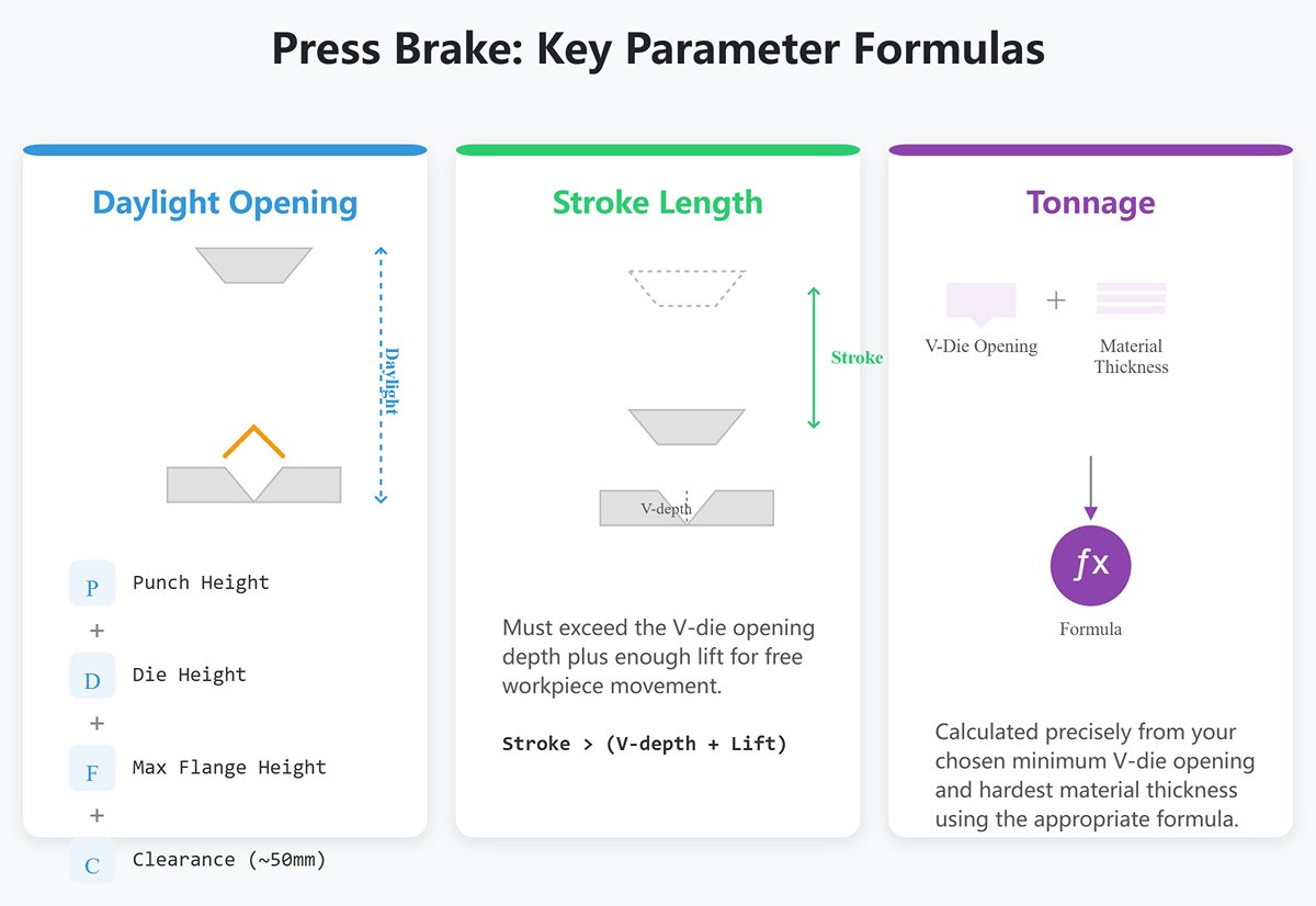
- Daylight opening = punch height + die height + maximum flange height of the workpiece + at least 50mm clearance for safe removal.
- Stroke length = must exceed the V-die opening depth plus enough lift for free workpiece movement.
- Tonnage = calculated precisely from your chosen minimum V-die opening and hardest material thickness using the appropriate formula.
By following this method, you won’t be buying a vague “general-purpose” machine—you’ll be investing in a precision production system tailored to your core products, delivering maximum value from day one. It fundamentally eliminates the risk of “buying it but not being able to use it.”
At this point, you have a complete selection framework—from fundamental calculations to high-level strategy. What was once a risky gamble clouded with uncertainty has now become a well-planned, expertly executed initiative firmly under your control, with success virtually assured.
V. Conclusion
In summary, choosing the right press brake is a multi-layered process. It starts with rejecting the "bigger is better" myth and understanding that "size" encompasses force, length, and precision control. A correct choice relies on accurate tonnage calculations, a practical four-step evaluation of your physical and production needs, and advanced strategies like TCO analysis to ensure long-term profitability.
To explore specific models and their technical specifications, you can find detailed information in our Brochures. By following this structured approach, you can confidently select a machine that is not just a purchase, but a strategic investment in your shop's future.
Ready to turn these insights into action? The expert team at ADH is here to help you navigate your options and configure a press brake solution tailored to your exact needs. To get started, contact us for a personalized consultation and let us help you invest in bending excellence.


