In modern fabrication, CNC press brake programming is the essential discipline that translates digital designs into precise, physical components. This guide provides a complete roadmap, taking you from foundational knowledge of machine physics and pre-production checks to the hands-on creation of your first part.
We will then advance to the strategic thinking of a process master, covering complex sequencing and advanced accuracy control, ultimately empowering you to transform potential into profit with every bend. For readers seeking deeper insights into software logic and automation, you can also consult the Guide to Press Brake Software for an in-depth look at digital bending systems.
I. Laying the Foundation: Core Insights and Universal Principles to Master Before Programming
Before typing your very first line of code, you must clearly understand that CNC bending programming is not merely about feeding instructions into a machine. It is a dialogue with precision engineering, materials science, and an entire value chain. To strengthen your understanding of these core concepts, check the Press Braking and CNC Technology Guide for more on machine coordination and process fundamentals.
True mastery lies in orchestrating all these elements. If your goal is to evolve from an operator to a true process artisan, you must begin by building an unshakable foundation of knowledge.
1.1 Deconstructing the CNC Press Brake: From Hardware to Its "Brain"
To program a machine effectively, you first need to understand its anatomy with the precision of a surgeon. At its core, a CNC press brake is a sophisticated system combining a "steel body" and a "digital brain." These two work in perfect harmony to transform cold, hard numbers into precise geometric forms.
- Steel Body (The Hardware): The Source of Power and Guarantee of Physical Precision
- Frame: The structural backbone of the machine, where rigidity is the primary guarantor of accuracy. High-end models often use an O-type (or G-type) closed frame instead of the open C-type design. Under the immense tension generated during bending, the O-type structure minimizes deflection, which is essential for achieving consistent angles across the full length.
- Ram & Bed: The ram (upper beam) drives the upper die downward to work in conjunction with the lower die fixed on the bed (lower beam), completing the bend. The parallelism between these two components is critical—state-of-the-art machines can maintain deviations as small as 0.01 mm.
- Hydraulic/Servo System: The "heart and muscles" of the machine. Advanced electro-hydraulic servo systems, equipped with high-response servo proportional valves, work in full closed-loop control with linear encoders. This allows independent microsecond-level, micron-precision adjustment of both hydraulic cylinders (Y1, Y2), ensuring absolute control over the ram’s posture—a key secret behind high-precision bending.
- Backgauge System: The positioning "ruler" for the workpiece, with the number of axes determining both flexibility and efficiency. Configurations range from a simple single X-axis (forward/backward movement) to sophisticated multi-axis setups (X, R, Z1, Z2) offering independent vertical, lateral, and longitudinal movement, enabling efficient, precise production of complex parts.
- Crowning System: The defining line between “acceptable” and “outstanding.” During bending, both the ram and bed inevitably develop a slight upward curve, causing the center angle to overshoot. A crowning system—whether mechanical wedges or hydraulic cylinders—applies a counteracting force to flatten this “smile.” Without understanding crowning, you cannot become a true programming master.
- Digital Brain (CNC Controller): The Machine’s Nervous System
- CNC Controller: This receives your input—angle, length, material, tooling—and, using its internal expert database and advanced algorithms, instantly calculates the precise ram depth (Y-axis position), backgauge location (X-axis), required tonnage, and crowning compensation.
- Software & HMI: Whether it’s Delem, Cybelec, or Salvagnini, interfaces vary but serve the same core purpose: an interactive gateway that translates your abstract design intent into a “digital language” the machine can execute with precision.
1.2 The Essence of Bending: Elevating 2D Blueprints into 3D Reality
Every line of bending code precisely describes a physical transformation of metal. Without understanding the physics behind it, programming becomes mere guesswork—never reaching the root of the problem.
- Elastic vs. Plastic Deformation: When force is applied to metal, it first undergoes elastic deformation (returning to its original shape once the force is removed). Only when stress exceeds the yield strength does it enter plastic deformation, resulting in permanent bending. Programming mastery lies in controlling force so it just surpasses the yield point to achieve the target angle, while staying well below the tensile strength to prevent fracture.
- K-Factor & Bend Allowance: Many mistakenly believe the neutral axis—the point in the material where length remains unchanged during bending—always lies exactly at the mid-thickness (50%). In reality, due to ductility, the neutral axis shifts inward. The K-factor defines this shift (K = distance from neutral axis to inner surface ÷ material thickness) and is crucial for calculating bend allowances when determining flat patterns. Skilled programmers maintain a tested K-factor chart tailored to various materials, thicknesses, and bend radii, rather than blindly trusting default software values.
- Springback: The most critical and challenging aspect of bending. Due to elastic recovery, once pressure is released, the material partially returns to its original form, making the final angle larger than intended. For example, to achieve a perfect 90°, you might need to bend to 88° so that springback yields the desired angle. Springback magnitude depends on material strength, thickness, bend radius, and other factors. In essence, virtually all advanced programming strategies revolve around predicting and compensating for springback with precision.
1.3 Mastering Universal Rules to Command Any System
The market offers a wide variety of CNC system brands and interfaces, but this should never be a barrier. Regardless of system differences, the underlying physics of bending and the essential parameters remain constant. Once you’ve mastered these “first principles,” you can operate confidently on any machine.
Every bending program revolves around three core input variables:
- Material Definition: Precisely define the material type (e.g., mild steel, stainless steel, aluminum) and thickness. These determine yield strength and springback characteristics, forming the basis for all controller calculations.
- Tooling Selection: This covers both the punch (particularly its tip radius) and the die (especially the width of the V-opening). Among all bending parameters, the V-opening width is one of the most critical. The classic “8× Rule”—that the V-width should be roughly eight times the sheet thickness—is a golden principle every programmer should know by heart. A smaller V-opening requires greater tonnage and produces a tighter inside bend radius; a larger V-opening does the opposite. This proportional relationship directly impacts both bend quality and the tonnage required.
- Geometric Parameters: The end goal—specifically, the target bend angle and flange length.
Whether you’re working in graphical programming or code-based programming, your core task is to supply the machine with the correct inputs above. A truly versatile programmer doesn’t just memorize menu locations in one system—they understand the underlying logic and mathematical relationships between these parameters.
1.4 Why Mastering Programming Is Your Core Competitive Edge
In the wave of automation, mere “button-pushers” are becoming increasingly vulnerable, while skilled programming specialists—true process engineers—are emerging as indispensable assets in manufacturing. This is not only about technical skill; it’s about the value you bring to your career.
- You are the engine of efficiency: A skilled programmer can optimize bend sequences to reduce part flips and repositioning, cutting cycle times by 10% or more. By leveraging offline programming, they enable uninterrupted production, pushing machine utilization to its limits.
- You are the guardian of cost: Every failed trial bend wastes material and labor. Programming expertise aims for First Time Right, minimizing test bends. Industry data shows seasoned programmers can cut material scrap rates by over 50%, saving real money.
- You are the source of quality: Part accuracy dictates final assembly fit and performance. A precise bend program ensures thousands of identical, in-spec parts, preventing costly rework or delays in welding and assembly—benefits that compound across the production chain.
- You are a value creator: Market data confirms that proficient CNC programmers earn far more than standard operators, often rivaling junior manufacturing engineers. You’re no longer just executing tasks—you’re solving complex process challenges, enabling high-value orders, and turning machine capability into company profit. You are the vital bridge between digital design and the physical world—the true “craftsman” of the digital manufacturing era.

II. Foolproof Programming: The Four Golden Pre-Setup Steps
In the strategic game of digital manufacturing, 90% of the outcome is decided at the opening. For CNC bending, that “opening” is the preparation before programming. Skipping these steps to “tweak on the fly” at the machine is a costly waste of time, material, and profit.
This Four-Step Golden Preparation Method is ingrained discipline for every master programmer—turning vague guesswork into precise science and paving the only path to First Time Right results.
For readers who want to further enhance their programming skills, you can also watch the detailed tutorial video — How to Perform Basic Programming Using the S875 Press Brake Controller.
2.1 Step One: Decoding the Drawing—Reading Process Information Like an Expert
A small drawing is the sole language linking design and manufacturing. An average operator sees dimensions; an expert sees constraints, intent, and hidden pitfalls. To become the latter, you must develop X-ray vision for technical details.
- Beyond dimensions and angles: Reading the “soul” of the drawing
- Tolerance: This is the “soul” of the drawing and the top directive shaping your process strategy. A ±0.5° angle tolerance and a ±0.1° tolerance demand drastically different machine precision, tooling condition, and programming approach. When you see tight tolerances, trigger your mental alarm: you’ll need precision-ground tooling, thorough first-piece inspection, and programming that prioritizes angle compensation over speed.
- Datum: Marked by A, B, C on the drawing, these reference surfaces or lines are the “absolute origin” for all dimensions. A common but fatal error is altering bend sequences for convenience, breaking the datum logic and causing cumulative dimensional errors. Bend sequences must always serve the datum requirements first.
- Surface requirements and special treatments: Is the drawing marked “scratch-free,” “film-protected,” or “heat-treated after bending”? These directly dictate tooling choice (e.g., non-marking dies or nylon inserts), process flow (e.g., film application), and parameter settings (e.g., compensating for heat-treatment distortion). Ignore these, and even dimension-perfect parts become scrap.
- Catching the unspoken hints: Spotting hidden traps in the drawing
- Inside radius (R): If the specified R is less than 0.8× the material thickness (R < 0.8T), this isn’t a simple air bend—it’s a process trap. It typically requires bottoming or even coining, with exponentially higher tonnage and extreme demands on tool and machine rigidity. If your equipment or tooling can’t handle it, consult the design engineer immediately, or risk tool damage or machine overload.
- Hole-to-bend distance: Check holes near the bend line. A good rule is: the distance from the hole edge to the bend line’s inner side should be at least 2.5× material thickness plus the inside bend radius. If too close, the hole will distort during bending. Anticipate this and decide whether to bend first then drill, or discuss design changes.
2.2 Step Two: Understanding the Material—Decoding Your Workpiece’s “DNA”
Seeing material simply as “3 mm stainless steel” is the mark of a beginner. A master programmer treats it as a living entity with a unique “DNA,” its properties full of variables.
- Different personalities of the “same” material: Never assume that the same type of material from different suppliers—or even different batches—shares identical mechanical properties. Yield strength and springback can vary by up to 15%, enough to turn a flawless program into a batch of rejects. For high-precision jobs, cut a small sample from the exact sheet you’ll be using and run a test bend before mass production. This five-minute step is the cheapest, most effective insurance you can buy—it may save you hours of rework and thousands in material losses.
- Recognizing the “Grain” — Rolling Direction: Sheet metal develops a directional grain during the rolling process. Bending with the grain requires less force but increases the risk of cracking, especially when working with small inside bend radii. Bending across the grain generally yields better performance. While the effect is minimal for most mild steels, it becomes critical when working with stainless steel, aluminum alloys, or high-strength steels. Whenever possible, align key bend lines at a 90° angle to the rolling direction.
2.3 Step Three: Choosing the Right Tooling — Preparing Before the Battle
Tooling is your weaponry. Entering a precision battle with the wrong tools guarantees defeat. Selecting the right tooling is a serious strategic decision that directly impacts bend quality, efficiency, and safety.
- The “Golden Rule” of the Lower Die V-Opening — Balancing Act:
- The “8× Rule” is the starting point, not the finish line: The V-opening width (V) should be approximately eight times the sheet thickness (t), or V ≈ 8t. This strikes the best balance between achieving a clean bend and maintaining reasonable tonnage requirements.
- Trade-offs in V-Opening Selection:
| Too small (<6t) | Too large (>12t) | |
|---|---|---|
| Required Tonnage | Increases sharply | Reduced |
| Inside Bend Radius | Becomes smaller | Increases |
| Issues | Outer surface is overstretched, leading to cracks; causes severe tooling wear. | Springback becomes harder to control; may prevent short flanges from forming properly. |
Your task is to find the optimal V-opening that balances the drawing’s radius requirements with the material’s characteristics.
- Upper Die Selection: Form Defines Function
- Punch Radius (R): The punch tip radius should be as close as possible to — or slightly smaller than — the specified inside bend radius. This is a key factor in achieving accurate bend radii.
- Punch Shape: For U-shaped profiles or complex negative angles, a standard straight punch may cause interference. In such cases, choose a gooseneck punch or other specialized tooling. During the programming simulation stage, always perform an interference check.
- Inspecting Tooling Condition: Examine your tooling like a connoisseur. Lightly run your fingernail along the cutting edge to detect any chips or wear. Even the smallest defect will be faithfully imprinted onto every part you produce. Ensure the upper and lower die centerlines are perfectly aligned — this is the physical foundation for consistent bend angles along the entire length.
2.4 Step Four: Safe Startup — The Pre-Flight Checklist That Eliminates 90% of Potential Risks

Before pressing the “Cycle Start” button, go through this methodical checklist. It’s not just about respecting safety — it’s the ultimate expression of professionalism. Like a pilot’s pre-flight inspection, it may seem routine and dull, but it can prevent 90% of disasters.
1. Clear Zone: Ensure the area around the machine, especially front and back, is free of tools, sheets, or debris. You and your workpiece need ample operating space.
2. Machine Status Check: Quickly scan hydraulic oil levels and pressure gauges to ensure they are within safe limits. Listen for any abnormal noises during startup.
3. Tooling Secure & Aligned: Confirm all clamping mechanisms are fully locked. Manually lower the ram slowly and visually check that the upper and lower tooling are perfectly aligned with even gaps. A single severe misaligned strike can destroy an expensive die set.
4. Safety System Test: Trigger the light curtain by hand or object to confirm it immediately halts ram movement. Locate and press the emergency stop button to verify it functions. Never operate a machine with a disabled safety system.
5. Machine Homing: Execute the homing (return-to-zero) routine. This sets an absolute coordinate “origin” for the CNC system — all subsequent positioning will be based on this reference. Skipping this step is like sailing without a compass.
Only after completing these “golden four steps” do you truly earn the right to program. You’re no longer just feeding blind commands into a machine — you’re a commander orchestrating precision. At this moment, you’re not injecting cold code, but certainty born from a deep understanding of the process.
III. Core Programming in Practice: From Zero Code to Your First Perfect Part
Theory matters only when it guides action. Now, we’ll turn the knowledge from the previous chapters into precise steps, transforming a flat 2D steel sheet into a flawless 3D component. For every programmer, this is the most exhilarating moment — the point where hesitation and guesswork vanish, and you feel the full power of controlling a precision machine.
3.1 Navigating the Control System: Familiarize Yourself with the “Cockpit”
When you stand before a modern CNC press brake, that glowing touchscreen is your cockpit. Whether it’s Delem, Cybelec, or another high-end system, their visual layouts may differ, but the underlying functional logic remains the same. Learning to navigate is your first step toward takeoff.
- Program Management: Your digital archive. This is where you create, load, copy, or delete programs — your repository of proven successes.
- Graphical Programming: Your main drawing board and design space. Most modern systems support graphical programming, allowing you to draw the part’s cross-section directly, much like in CAD, or import DXF/DWG files from the design department. This is the first step toward true “what you see is what you get” programming.
- Parameter Input: Your dashboard and mission briefing. Once the part geometry is defined, the system will guide you to input all critical process details here, such as material type and tooling.
- Simulation: Your high-fidelity flight simulator. Before consuming any material, you can preview the entire production sequence here — we’ll discuss its irreplaceable value shortly.
- Production Mode: After programming and simulation are complete and verified, switch to this mode. Here, digital instructions become physical motion, and value creation begins.
3.2 Creating Your First Program: Input the “Five Core Parameters”
Let’s start with a classic beginner’s task: Take a 2.0 mm thick, 100 mm wide sheet of low-carbon steel and bend it to a 90° angle, with one flange measuring 50 mm in length.
- Create a New Program: In the program management section, click “New Program” and give it a clear name, such as “TEST-PART-001.”
- Define the Geometry: In the graphical programming area, draw an L-shaped cross-section. Alternatively, in table mode, directly enter the lengths of the two sides and the angle between them.
- First side length:
50.0mm - Bend angle:
90.0° - Second side length: Enter the desired dimension, for example
100.0mm.
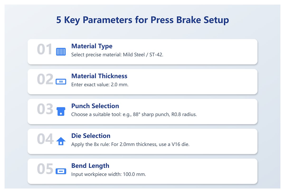
- Enter the “Five Core Parameters”: At this stage, the system will automatically guide you to the parameter input area. Just like a pilot entering a flight plan, you must precisely enter the following five critical details that determine success or failure:
- Parameter 1: Material Type: In the material library, select “Mild Steel / ST-42” with precision. Never choose a vague or incorrect material.
- Parameter 2: Material Thickness: Enter
2.0mm. This is the foundation of all calculations; even the smallest error will be amplified. - Parameter 3: Punch: Click to select from the tool library a punch that is actually installed on your machine and suitable for the job, such as an 88° sharp punch with R0.8 radius.
- Parameter 4: Die: Click to select from the tool library the die currently installed on your machine. Following the “8× rule,” for a 2.0mm thick plate, the V-opening should be around 16mm, so choose a V16 die.
- Parameter 5: Bend Length: Enter the workpiece width
100.0mm.
Once these five steps are completed, you will have built the core framework of your first program. You’ve told the machine, in the most concise numerical language: “Which tools to use, on what material, to make what kind of bend.”
3.3 Understanding the Logic Behind the Numbers: Making Parameters Less Mysterious
After entering the “Five Core Parameters,” the CNC’s “brain” runs a series of complex calculations in milliseconds behind the scenes. Understanding these calculations transforms you from a mere “operator” into a true “process engineer,” eliminating the mystery of programming.
- How does it determine slider depth? The CNC controller doesn’t directly “know” where 90° is. Based on your chosen punch, die, and material thickness, it uses geometric calculations to determine how far the punch must penetrate into the die to produce a 90° bend—this is called the penetration depth. This calculation assumes the air bending model, where the sheet only contacts the punch tip and the two shoulders of the die.
- How does it compensate for springback? Once you select the material type, the CNC consults its internal material database to find a theoretical springback value for that specific material, thickness, and tooling combination. It then increases the penetration depth to “overbend” (for example, to 88.5°), so that after the pressure is released and the material springs back, you end up with exactly 90°. This is a core aspect of the CNC’s intelligence.
- How does it calculate required tonnage? The CNC uses the selected material (primarily its tensile strength), thickness, V-opening width, and bend length in a built-in tonnage formula (e.g.,
P = (1.42 * σb * S * L) / V) to estimate the pressure needed for the bend. This value is displayed in real time. If the tonnage exceeds the limits of your tooling or machine, the system immediately issues a red warning, protecting you, your tools, and the equipment. - How does it position the backgauge? To achieve a 50mm flange length, the backgauge position is not simply set to 50mm. The CNC calculates the developed length of the material after bending—based on parameters such as the K-factor and bend allowance—and from that determines the precise physical position of the backgauge fingers, ensuring the bend line aligns perfectly with the centerline of the punch and die.
3.4 Simulation: Your Digital Safety Net Against Collisions
Before your finger touches the “Cycle Start” button, there’s one step you must never skip: click “Simulation.” This is far more than a decorative animation—it’s your “digital safety net” that prevents 99% of collision risks and helps optimize your process.
In the simulation interface, you’ll see a complete virtual machining sequence with 3D models of your workpiece, tooling, backgauge, and machine. As a strict inspector, focus on:
- Collision Check: During bending and flipping, does any part of the workpiece come into contact with the machine’s slider, frame, worktable, or backgauge? Any real collision could result in losses worth thousands, even tens of thousands.
- Reachability: For complex parts, can the backgauge smoothly move into all required positions? Are there any physical limitations?
- Handling Sequence: For parts with multiple bends, the simulation will suggest a bending order and show flipping or rotating actions. Consider whether this is the most efficient sequence. Could reordering reduce a difficult flip?
Only when the simulation runs smoothly and shows no warnings do you have the green light to proceed.
3.5 First-Part Test Bend and Calibration: Closing the Loop from Virtual to Real
Once the simulation passes perfectly, it’s time for the most exciting moment: the first-part test bend. This is the critical link between virtual programming and physical reality, the step where theory turns into results. The difference between a professional and an amateur lies in executing this step scientifically.
- Prepare Test Material: Use a piece from the exact same batch as the actual product, cut to the required size. Do not substitute with offcuts or different thicknesses.
- Single-Step Execution: In production mode, select “Single Step” or “MDI” mode, press the foot pedal, and complete the bend. Feel the machine’s force and listen to the sound of the metal yielding.
- Precision Measurement: Using a high-quality 90° square with feeler gauges or a digital protractor, measure the actual bend angle at the left, center, and right of the workpiece. Also, use calipers to measure the actual flange length.
- Calibration (Angle and Length Compensation):
- Angle deviation: Suppose your measured average angle is 90.5°, which is 0.5° larger than the target. This indicates that springback is greater than the system anticipated. Go to the program’s angle correction page and enter a -0.5° compensation. Essentially, you’re telling the CNC: “Your calculation is off—next time, press in an extra 0.5°.”
- Length deviation: If your measured flange length is 49.8mm, 0.2mm shorter than the target, open the backgauge correction page and enter a +0.2mm compensation. This instructs the backgauge: “Move outward by an additional 0.2mm.”
- Re-test and verify: After saving the correction values, use another test piece to bend again. This time, you should achieve a near-perfect 90° angle and a 50mm flange. When your measurements fall within the drawing’s tolerance range, your first flawless workpiece is complete!
Congratulations! You’ve not only performed a bending operation, but completed a full scientific loop—from theoretical understanding to parameter entry, to physical verification and digital adjustment. You’ve grasped the core logic behind CNC bending programming.
IV. Advanced Programming and Precision Control: The Transformation from Operator to Process Master
Once every step of basic programming has become second nature, the real challenge begins. From here, you’ll evolve from a directive-following “operator” into a “process master” who foresees problems and crafts solutions. The essence of this journey lies in mastering strategies beyond the ordinary, handling specialized techniques, and achieving ultimate precision control.
4.1 Mastering Bending Sequence Strategies for Complex Parts
For a complex part with a dozen or even dozens of bends, the sequence is no longer as simple as “left first, then right”—it becomes a strategic plan that determines success or failure. A wrong sequence might cause interference that halts progress, or even scrap the part entirely. This tests not your memory, but your 3D spatial visualization and logical foresight.
Basic rules (Operator’s checklist):
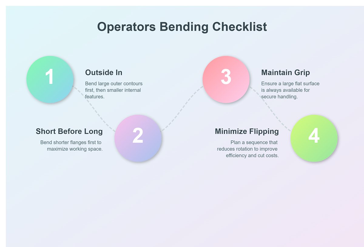
These are the traffic rules you must follow—they solve about 80% of problems.
- From outside in: Generally, bend the large outer contours first, then move to smaller internal features.
- Short before long: Bend shorter flanges first, as they have less impact on flipping and positioning longer flanges later, leaving more working space for subsequent steps.
- Maintain grip: Ensure there’s always a sufficiently large flat surface for the operator to hold and position the part securely during bending. Losing a stable grip point is a common rookie mistake.
- Minimize flipping: Plan a sequence that reduces unnecessary flipping and rotation—this directly improves efficiency. Every extra movement wastes time and adds cost.
Master-level strategic thinking: The art beyond the checklist
When basic rules conflict, the master’s mindset shines. They focus not on “what’s next,” but on “how it ends.”
- Interference prediction and “making way” strategy: A master mentally runs a 3D simulation of how the part, tooling, and machine will move together. They foresee not only collisions between the part and the machine, but also self-interference within the part. For example, when bending a box, closing the final edge is often the trickiest step. A master uses offline programming software to simulate multiple closure sequences, and may even choose an earlier step that seems awkward just to “make way” for the last bend. They know that sometimes a temporary retreat leads to ultimate progress.
- “Datum lock” principle: For high-precision parts, the master examines the drawings like a detective, identifying the critical datum that interfaces with other components. They will ensure this datum’s bending accuracy at all costs—even if it means extra flips—before tackling secondary bends. They understand that errors accumulate, so the source must be locked in. Operators focus on getting each bend “right,” while masters aim to make the entire part “fit” perfectly.
4.2 Special Process Programming Techniques
Mastering standard bends is only the foundation—being adept with special processes is what multiplies your value. These are the rare but powerful “special forces” in your toolbox.
- Hemming: This process folds the sheet’s edge back onto itself to create a safe, sturdy edge. It’s not done in a single step, but through a precise two-step sequence:
- Pre-bending: First, use a sharp-angle punch (such as 30° or 28°) to bend the sheet into a tight acute angle, typically 25–30°. Precision here is critical to set up the flattening phase.
- Flattening: Next, switch to a flat hemming tool, or use the press brake’s ram with protective shims, to apply high pressure and flatten the acute bend into a smooth edge. Programming must precisely control tonnage and bottom dead center—too little pressure leaves it incomplete, too much can damage tooling or leave permanent marks.
- Large Radius Bending / "Bump" Bending: When the design calls for a radius far larger than your tooling’s physical radius, use multi-step incremental bending. The principle is to create the curve from many small straight bends, just like sketching with short strokes.
- Programming essentials: Calculate the step length (distance between bends) and the bend angle for each step. These determine the final radius and smoothness.
Smaller steps and angles yield a smoother curvebut take more time. Modern CNC systems often have built-in arc programming—just input the target radius, angle, and sheet length, and the system will compute step length and angles. Your role is to understand the principles and choose the optimal balance between finish and efficiency.
- Programming essentials: Calculate the step length (distance between bends) and the bend angle for each step. These determine the final radius and smoothness.
- Z-Bends: This involves making two bends in opposite directions on the same part. When the distance between bends (the middle segment of the “Z”) is very short, the challenge is that the first flange can easily interfere with the press brake’s throat or ram during the second bend.
- Solution matrix:
- 1. Tooling upgrade: Use high-neck gooseneck punches to provide extra clearance.
- 2. Sequence optimization: If possible, place the Z-bend at the part’s edge and start bending from the edge.
- 3. Unconventional methods: For extreme Z-bends, you may need to reverse-mount the bottom die or design a custom-shaped die to avoid interference.
- Solution matrix:
4.3 Advanced Precision Control Strategies
When your aim is no longer just “acceptable” but to meet ±0.1° tolerance limits, you’ll need to employ advanced strategies with surgical precision.
- Dynamic Material Library Calibration: The CNC system’s built‑in material library is merely a “theoretical average.” True masters never rely on this database alone, knowing that yield strength and spring‑back characteristics vary across batches and steel mills. Instead, they develop their own dynamic material library.
- Hands‑on Practice: When a new batch of material arrives, take a few sample pieces and run them through your most frequently used tooling sets (e.g., V8, V12, V16), bending them to standard angles (such as 45°, 90°, and 135°). Measure the actual spring‑back with precision and record the values. In your CNC system, duplicate a standard material entry (like “low carbon steel”) and rename it to something like “XX Steel Mill – 2mm Low Carbon Steel – Nov 2025 Batch.” Input the measured spring‑back correction values into this new material’s parameter table. When producing parts from this batch, use the personally calibrated material entry. This practice sets you apart from 90% of operators.
- Applying and Reflecting on Adaptive Bending Technology: Modern high‑end press brakes are equipped with a Laser Angle Measurement System (LAMS). This system continuously measures the bend angle during forming and feeds the data back to the CNC, which then adjusts the ram depth in real time until the target angle is achieved. Known as adaptive bending, it’s the ultimate tool for achieving “first‑piece perfection.” But masters use it with discernment, not blind faith.
- Know Its Limitations: It is not infallible. Highly reflective materials, such as mirror‑finish stainless steel or brushed panels, or bend lines positioned too close to holes, can cause laser readings to be inaccurate. Masters are aware of these weaknesses and avoid being misled.
- Learn to ‘Train’ It: Within the system settings, you can fine‑tune parameters such as measurement start time, frequency, and algorithm mode. Masters adjust these settings according to material type and part characteristics, much like training a service dog, to ensure more consistent and reliable performance.
- Know When to Turn It Off: In scenarios where efficiency takes precedence over tight tolerances, or when you anticipate laser interference, masters will decisively disable the adaptive system and revert to their own meticulously calibrated database. They trust their experience, knowing this saves the time otherwise spent on measurement—a confidence rooted in deep understanding.
- Thermal Drift Compensation: This is precision control at a grandmaster level. After several hours of continuous operation, the press brake’s hydraulic oil temperature can rise by dozens of degrees. This heat reduces oil viscosity, affecting servo valve response speed, and ultimately causing a predictable, gradual drift in bend angles.
- The Ultimate Strategy: Top‑tier CNC systems feature thermal drift compensation. Using temperature sensors, the system monitors oil temperature changes and automatically fine‑tunes the ram’s bottom dead center based on pre‑set compensation curves. The master’s role is to log oil temperature and angle deviation every hour over a full shift, plotting a unique “temperature‑angle compensation curve” for that specific machine and programming it into the system. From then on, the machine becomes an extension of the operator’s own body, maintaining unwavering accuracy no matter how long the work continues.
By mastering these strategies and techniques, you move beyond simply executing programs. You become the controller, optimizer, and forecaster of the entire bending process. Your worth will rise from piece‑rate wages to the status of an irreplaceable core technical asset.
V. Conclusion
In summary, mastering CNC press brake programming is a journey from understanding foundational principles to executing advanced, strategic control. We have demystified the machine's core components and the physics of bending, established a four-step pre-flight checklist for flawless preparation, and provided a hands-on guide to creating and calibrating your first perfect part.
Finally, we explored the expert-level strategies for sequencing complex parts, programming special processes, and achieving ultimate precision. This comprehensive roadmap empowers you to transform digital designs into tangible, profitable, and perfect components.
Ready to put this knowledge to work with equipment built for precision and reliability? At ADH Machine Tool, our press brakes are engineered to bring your programming skills to life. You can find detailed specifications in our online Brochures. Contact us today to explore solutions that match your ambition and let our experts help you elevate your craft from operator to artisan.


