At the heart of precision bending is one question: how does a hydraulic press brake stay synchronized?. This synchronization—the perfectly parallel movement of the machine's ram—is the lifeline for accuracy.
This guide traces its evolution from mechanical bars to today's intelligent CNC servo systems, explaining how modern machines achieve precision and how to maintain it through preventative care.
I. The Value of Synchronization: Why It’s the Lifeline of Successful Bending
In precision metal forming, even a millimeter’s deviation can turn valuable components into costly failures. The hydraulic press brake—a master of transforming two-dimensional sheets into three-dimensional forms—owes every promise of accuracy to an invisible lifeline: synchronization.
It’s not a nice-to-have feature but the very soul of the machine. If synchronization fails, no amount of tonnage or tooling sharpness will save it from producing nothing but scrap.
1.1 Core Breakdown: What Exactly Is Press Brake Synchronization?
Imagine commanding two independent strongmen to lift a long barbell together. To keep that bar perfectly level through the entire motion, every detail—from timing and speed to final height—must be perfectly matched between them.
That’s the essence of synchronization in a press brake.
Synchronization in a press brake means that the two separate hydraulic cylinders driving the ram downward must move in millisecond, micron-level harmony throughout the entire stroke.
These cylinders are inherently independent actors. Without a superior command system, slight differences in oil temperature, seal friction, or pipeline resistance will be amplified—causing one side of the ram to move faster or deeper than the other.
The synchronization system’s mission is to tame such variability, ensuring the ram remains perfectly parallel to the workbench under any load, executing movements with precision and discipline.
1.2 The Pain Made Visible: What Happens When Synchronization Fails?
Synchronization failure isn’t an abstract technical term—it’s a real-world workshop disaster movie. When this lifeline snaps, what you see goes far beyond mere 'minor deviation':
- Consistent Production of Tapered Scrap: The most immediate symptom—perfect sheet metal goes in, tapered scrap comes out. Angles differ at each end, not by accident but predictably and repeatedly. Each defective piece erodes your profit margin.
- Twisted, “Taffy-Like” Distortion of Workpieces: With long, thin sheets, even slight ram tilt introduces devastating torsional stress—like wringing a towel. What emerges isn’t a bent part but a twisted, internally damaged piece of metal fit only for scrap.
- Molds and Equipment Suffer “Chronic,” Silent Damage: Synchronization deviation means one die half absorbs excessive impact while the other barely makes contact. This uneven load is the silent killer of equipment, leading to:
- Abnormal edge chipping of dies
- Unilateral wear of guide rails
- Premature aging and failure of cylinder seals
Ultimately, you pay dearly in replacement parts and prolonged downtime.
- The Efficiency Black Hole: Operators fall into a repetitive cycle of trial bends, measurement, corrective tapping, and re-adjustment. Production rhythm collapses, and morale follows suit.
In essence, synchronization issues act as multipliers of cost, destroyers of quality, and hidden operational risks lurking deep within the production line.
1.3 Clarifying the Concepts: Synchronization, Balancing, and Compensation
To become a true bending expert, one must understand how these three “siblings” differ. They work together but address distinct physical challenges. Here’s a vivid analogy to grasp the distinctions:
Scenario: Two workers carry a heavy box using a long wooden plank.
- Synchronization: Both workers must lift together, move together, and lower together to keep the plank level. This represents controlling the vertical alignment of both sides of the ram.
- Balancing: The box isn’t placed at the center—it’s offset to one side. The worker on the heavier side must exert more force, while the other adjusts accordingly to maintain balance. This reflects the ability to handle eccentric loads.
- Compensation: The plank is so long and the box so heavy that the middle bends downward. To restore flatness, a support must be added underneath. This corresponds to correcting structural deflection in the press brake.
The table below provides a clear reference framework:
| Concept | Synchronization | Balancing | Compensation |
|---|---|---|---|
| Problem Addressed | Vertical position difference between ram sides (Y-axis) | Uneven load on ram (eccentric bending) | Elastic deformation of the machine structure (deflection) |
| Everyday Analogy | Two people lifting in perfect sync | Adjusting strength to handle an off-center load | Placing a jack under the middle of a plank |
| Technical Goal | Ensure consistent bending angle along the entire length | Maintain accuracy and stability even under off-center loads | Ensure perfectly straight bends, eliminating “deeper middle, shallow ends” |
| Implementation | Torsion bar (mechanical linkage) or electro-hydraulic servo feedback control | Torsion bar’s rigidity or independent cylinder control in servo systems | Mechanical deflection compensation (wedge adjustment) or hydraulic compensation (auxiliary cylinders) |
In short: synchronization ensures angle uniformity, compensation ensures straightness, and balancing is the advanced capability that enables synchronization under complex loading conditions. Understanding this marks your first step from operator to process master.
II. The Road of Technological Evolution: A Deep Dive into Three Generations of Synchronization Mechanisms
Synchronization technology in press brakes isn’t a single invention but the result of a long, continuous pursuit of precision, efficiency, and intelligence in manufacturing. It evolved from purely mechanical constraints to electronic control and, finally, to intelligent servo systems powered by algorithms. Understanding this progression is to grasp the foundation of modern precision bending.
2.1 First Generation: Mechanical Rigid Synchronization (Torsion Bar Type)
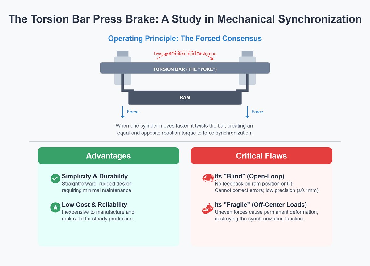
This marks the “classical era” of press brake synchronization. The core concept was to achieve synchronization through uncompromising mechanical rigidity—a physically enforced agreement. Its most iconic form is the torsion bar synchronization mechanism.
- Operating Principle: Imagine a sturdy steel yoke connecting two weightlifters’ arms. That yoke is the torsion bar. It spans the top of the press brake, linked to both hydraulic piston rods through connecting arms. When the hydraulic system drives the ram downward, if one cylinder tries to get ahead, its extra force twists the torsion bar, which immediately generates an equal and opposite reaction torque—pulling the faster side back while urging the slower side forward. It’s a beautifully simple yet brutally effective forced consensus mechanism.
- Advantages: Its beauty lies in its simplicity. The design is straightforward, rugged, and exceptionally durable, requiring minimal maintenance. In an era focused on steady production with only modest demands for absolute precision, the torsion bar reigned supreme for decades thanks to its low cost and rock-solid reliability.
- Critical Flaws: That same simplicity is also its greatest limitation. The torsion bar synchronization system is an executor with no "brain" and no "senses":
- It’s “blind”: This is a purely open-loop system. The control unit’s only role is to issue “down” and “stop” commands, without any awareness of the ram’s actual position during movement or whether it is tilting. It cannot perform any corrections. Synchronization accuracy depends entirely on the manufacturing tolerances and rigidity of the mechanical structure, typically hovering around ±0.1 mm—a level of roughness that is unacceptable by modern standards.
- It’s “fragile”: Its Achilles’ heel is its inability to withstand off-center loading. When workpieces are bent away from the center, the hydraulic cylinders on each side experience vastly different forces, forcing the torsion bar to endure massive, uneven torsional loads. Over time, this leads to permanent plastic deformation—like a yoke twisted out of shape—completely destroying its synchronization function and leaving it virtually beyond repair. This marked the end of its relevance in the face of today’s flexible, complex manufacturing needs.
2.2 Second Generation: Electro-Hydraulic Proportional Synchronization (Open-Loop / Basic Closed-Loop)
With the integration of electronics and hydraulics, synchronization control entered the “electrification era.” The advent of the proportional valve made it possible to precisely regulate hydraulic flow using electrical signals, marking a pivotal step forward in synchronization technology.
- Operating Principle: At the heart of this generation lies the replacement of traditional on/off hydraulic valves with electro-hydraulic proportional valves. Instead of simply opening or closing the oil circuit, the CNC system can now send continuously variable voltage or current signals to each side’s proportional valve, finely adjusting the valve opening to control the flow into each hydraulic cylinder, and thus indirectly controlling the ram’s movement.
- In more advanced basic closed-loop systems, designers added position sensors (such as rotary encoders) to the ram, giving the CNC system its first true “view” of the ram’s approximate position. The system could then compare feedback to the target position and make limited adjustments to the proportional valve commands.
- Advancements: This was a leap from “mechanical constraint” to “active adjustment.” Control flexibility and precision improved dramatically (to around ±0.05 mm), and the system gained some resistance to off-center loads, as the flow to each cylinder could be partially controlled independently.
- Era Limitations: Despite having acquired “eyes” and “a voice,” its reaction speed and decision-making abilities were still rudimentary.
- Sluggish Response: Standard proportional valves have limited response frequency. Faced with the rapid variations that occur during bending, adjustments often lag slightly behind, preventing further improvements in precision.
- Coarse Control: Proportional valves suffer from dead zones and nonlinearities, making them far less precise than the servo valves that came later. Basic closed-loop algorithms were also relatively simple—more akin to “rough adjustments” than true real-time, high-precision error correction. It was a remarkable step forward, but still short of perfect synchronization.
2.3 Third Generation: CNC Electro-Hydraulic Servo Synchronization (Full Closed-Loop)
This was not a mere upgrade—it was a revolution. CNC Electro-Hydraulic Servo Synchronization is the gold standard in today’s high-performance press brakes, ushering synchronization control into the “intelligent era.”
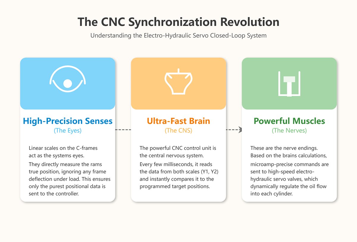
- Operating Principle: This is a flawless closed-loop servo system made up of “high-precision senses,” an “ultra-fast brain,” and “powerful muscles.”
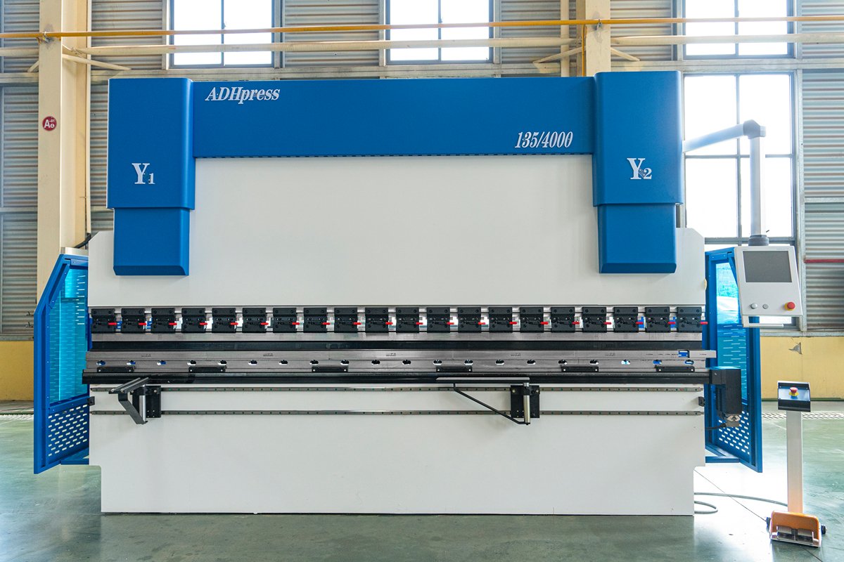
- High-Precision Senses (Eyes): Independent linear scales are mounted at the throat openings (C-frames) on both sides of the machine. They directly measure the ram’s true position relative to the worktable, cleverly eliminating errors caused by frame deflection under load, ensuring only the purest positional data is captured.
- Ultra-Fast Brain (Central Nervous System): The powerful CNC control unit reads the real-time positional data from both linear scales (Y1 and Y2) every few milliseconds, instantly comparing it to the programmed target positions.
- Powerful Muscles (Nerve Endings): Based on even the tiniest detected deviations, the CNC uses advanced algorithms to send microamp-precise commands in real time to each side’s high-speed electro-hydraulic servo valve, dynamically regulating the flow into each cylinder.
This “read–compare–command–execute” cycle occurs at speeds imperceptible to humans. Any tendency toward desynchronization is detected and corrected within a fraction of a millisecond.
- Definitive Advantages:
- Extreme Precision: The Y1 and Y2 axes can easily achieve repeat positioning accuracy of ±0.01 mm—or even ±0.005 mm—levels unattainable by previous generations.
- Absolute Off-Center Load Resistance: With each cylinder under completely independent intelligent servo control, the system can effortlessly handle extreme off-center conditions. When one side experiences higher load, the system instantly boosts pressure there while reducing it on the other side, keeping the ram perfectly parallel at all times.
- High-Level Intelligence: It not only synchronizes but manages the entire bending cycle. From rapid descent, forming, dwell, to return stroke, every parameter—speed, position, pressure—can be precisely programmed and optimized. It can also integrate seamlessly with automatic crowning systems, achieving truly flawless bends.
2.4 Three-Generation Synchronization Technology Comparison Matrix
To help you instantly grasp the fundamental differences among the three generations, the table below serves as your ultimate decision-making reference.
| Feature Comparison | First Generation: Mechanical Rigid Synchronization (Torsion Shaft) | Second Generation: Electro-Hydraulic Proportional Synchronization (Open-Loop/Simple Closed-Loop) | Third Generation: CNC Electro-Hydraulic Servo Synchronization (Full Closed-Loop) |
|---|---|---|---|
| Control Philosophy | Mechanically enforced, passive constraint | Electrically regulated, basic intervention | Servo intelligence, proactive closed-loop |
| Core Components | Rigid torsion shaft | Electro-hydraulic proportional valve, encoder | High-speed servo valve, independent linear scale, CNC controller |
| Control Mode | Pure open-loop | Open-loop or simple closed-loop | Full closed-loop |
| Synchronization Accuracy | Low (approx. ±0.1 mm) | Moderate (approx. ±0.05 mm) | Extremely high (below ±0.01 mm) |
| Load Offset Resistance | None (offset load causes damage) | Limited, dependent on valve performance | Very strong (independent servo on each cylinder) |
| Feedback Mechanism | No feedback – system is “blind” | None or basic position feedback | Real-time, high-precision dual linear scale feedback |
| Error Correction | None – relies solely on mechanical rigidity | Limited dynamic adjustment with lag | Real-time, proactive, millisecond-level dynamic correction |
| Application Scenarios | Budget machines with low precision requirements | Mid-range CNC machines | High-performance, high-precision CNC bending centers |
| Value Positioning | Meets the “basic” – fulfills fundamental bending needs | Meets the “good” – increases efficiency and versatility | Meets the “precision” – achieves extreme accuracy and automation |
III. Mastering the Modern Core: The Working Logic of CNC Electro-Hydraulic Servo Synchronization Systems
If torsion shaft synchronization is akin to brute-force muscle memory, then a CNC electro-hydraulic servo synchronization system is more like a highly evolved organism with a sophisticated brain and a finely tuned nervous system.
It abandons mechanical rigidity and passive response in favor of a realm ruled by code, algorithms, and precision sensors. Understanding its operational logic is the gateway to unlocking advanced precision forming technology.
3.1 The Millisecond “Think–Act” Loop of Closed-Loop Control
At the heart of this system is a relentless, millisecond-by-millisecond “think–act” cycle. Imagine a world-class tightrope walker, constantly sensing the slightest shift in balance and instantly adjusting muscle tension to remain steady. In engineering terms, this is Closed-Loop Control, which can be broken down into six essential steps:
- Command Input: The operator sets the target bending depth in the CNC control system (for example, Y1 = 100.00 mm, Y2 = 100.00 mm). The moment the foot pedal is pressed, the CNC “brain” sends initial movement commands to the electro-hydraulic servo valves on both sides of the ram.
- Servo Actuation: Upon receiving the electrical signal, the servo valves—the system’s “nerve endings”—open with extraordinary precision and speed, directing high-pressure hydraulic oil at controlled flow rates and pressures into the cylinders to drive the ram downward at the programmed speed.
- Real-Time Monitoring: High-precision linear scales mounted on independent C-frame supports move in sync with the ram. Their read heads continuously transmit the absolute positions of each side (Y1 and Y2 axes) as digital signals back to the CNC system without pause.
- High-Speed Comparison: In each scan cycle—typically under one millisecond—the CNC “brain” compares the real-time position data from the scales (e.g., Y1 = 99.85 mm, Y2 = 99.87 mm) against the target values (100.00 mm), instantly calculating minute discrepancies down to the micrometer.
- Algorithmic Correction: This is where the system’s intelligence shines. Inside the CNC runs a sophisticated PID (Proportional–Integral–Derivative) control algorithm. Based on the magnitude, duration, and trend of the error, it computes an optimal micro-adjustment signal—perhaps increasing the oil flow to the Y1 cylinder by a few thousandths of a percent while reducing the Y2 cylinder’s flow by a fraction of that.
- Command Adjustment: The CNC sends this refined correction signal back to the servo valves, which immediately adjust their openings to alter cylinder flow rates. Within the next millisecond, the ram’s position and speed are corrected accordingly.
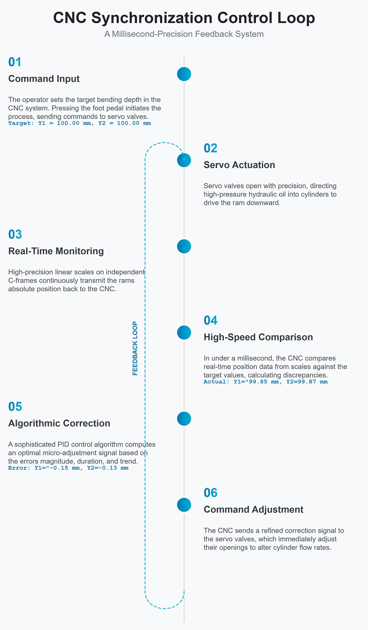
These six steps form a flawless closed loop. From rapid descent to bend completion, this cycle repeats thousands of times. It ensures that any factor threatening synchronization—whether a subtle change in oil temperature or uneven seal friction—is detected and eliminated almost instantly, keeping Y1 and Y2 perfectly aligned with micrometer-level precision.
3.2 The Unsung Heroes: Components That Determine Synchronization Success
The perfection of this precision loop depends on seamless collaboration among several “unsung heroes.” Much like sections of a world-class orchestra, if any one part falters, the system’s performance suffers, producing the discord of measurable error.
- CNC Controller (The Brain): The chief conductor of the system. Its prowess lies not only in processing speed but—more critically—in the sophistication of its control algorithms. Different controller brands vary widely in handling load imbalance, damping vibrations, and optimizing speed curves. A top-tier controller can make bending faster, steadier, and more accurate, much like an experienced conductor anticipating and resolving every hint of dissonance.
- Linear or Magnetic Scales (The Eyes): These serve as the system’s “eyes,” delivering precise, reliable position feedback. Their quality and installation method directly affect the accuracy of the information received by the brain.
- Resolution: High-precision scales can reach resolutions of 1 μm (0.001 mm) or better, providing the physical foundation for micrometer-level control.
- Installation Method: This is the decisive detail that separates true professionals from amateurs. On a top-tier press brake, the linear scale must be mounted on an independent C-frame measuring bracket, with its upper end connected to the ram and lower end to the worktable. Why? Under massive tonnage, the machine’s side frames (the throat) inevitably flex outward. If the scale is mounted directly to the side frame, this deformation will “fool” the scale into reading a deeper stroke than reality, resulting in under-bent angles. The independent C-frame, however, is unaffected by frame deflection and measures only the true relative distance between the ram and the worktable, ensuring feedback of uncompromised accuracy.
- Electro-Hydraulic Servo Valve (The Nerves and Muscles) This is the ultimate executor of commands, and its performance determines the system’s response speed and control precision. Compared to standard proportional valves, a servo valve is the real “special forces” operator:
- Ultra-High Frequency Response: Reacts to changes in control signals with lightning speed, virtually without delay, ensuring corrective commands are executed instantly.
- Zero Deadband: Even the faintest control signal can move the spool, enabling true fine-tuning.
- High Linearity: Output flow is precisely proportional to input signals, delivering pinpoint control exactly where it’s needed.
Simply put, without a high-speed electro-hydraulic servo valve, there can be no truly high-precision electro-hydraulic synchronization system.
- Hydraulic System (The Circulatory System) While control is the brain, a stable, clean hydraulic system is the power foundation behind it all. Only high-quality pumps, hoses, seals, and finely filtered hydraulic oil can reliably translate the servo valve’s precise commands into smooth cylinder motion. Any leaks, pressure fluctuations, or oil contamination act like “blood clots” in the circulatory system, severely disrupting servo performance—leaving the system intelligent but powerless.
IV. Prevention is Better than Cure: Preventive Maintenance Checklist for the Synchronization System
A CNC electro-hydraulic servo press brake’s synchronization system is like a top-tier F1 driver—capable of lightning-fast reactions and micron-level control. But even the best driver needs a disciplined pit crew to keep the car in peak condition. A single loose bolt or uneven tire wear can lead to catastrophic consequences. Readers who want to dive deeper into the working principles can refer to how does a press brake work.
Preventive maintenance is the “championship pit crew” for your precision machine. It’s not an optional extra—it’s the only rule that safeguards accuracy, extends lifespan, and prevents catastrophic downtime. Below is a tiered maintenance framework, from operators to professional engineers, that serves as your operational bible for keeping the synchronization system precise over the long haul.
4.1 Operator-Level Daily Checks (Every Day/Shift): The Sensory Early Warning Network
Operators, working closely with the machine day in and day out, form the first line of defense. Their senses—sight, hearing, and touch—constitute the most sensitive and effective early warning system. These checks take less than five minutes but are invaluable. If you're new to daily operation routines, you may also review step-by-step guidance in how to use press brake.
- Startup Baseline Confirmation: The Machine’s “Morning Roll Call”
- Action: On the first startup of the day, run the “Homing” procedure.
- Observation Points: This is not a ritual to skip. Judge like a referee: do both sides of the ram (Y1/Y2) reach the top dead center smoothly, quietly, and in perfect sync? Does the CNC display reset coordinates precisely to zero? Any lag, abnormal vibration, or alarms on one side are the system’s first distress signals and must be reported immediately.
- No-Load Stroke Visual Check: The Most Honest Physical Feedback
- Action: With no workpiece in place, use manual (JOG) mode to slowly lower the ram until the punch tip is about 1–2 mm from the die opening.
- Observation Points: Crouch so your eyes are level with the worktable. Check if the gap between punch and die is razor-straight and even along the full length of the ram. This is the most direct test of synchronization accuracy. Any visible “wedge-shaped” gap means the system’s precision has already been compromised. The concept of press brake parallelism can help operators better understand what these deviations imply.
- Acoustic and Olfactory Diagnostics: Listening to the “Pulse of Health”
- Action: Stay alert during normal operation, especially at the instant of bending under pressure.
- Diagnostic Signals:
- Healthy “Heartbeat”: A steady, consistent humming from the hydraulic system.
- Dangerous “Scream”: A piercing whine from the pump station may indicate air in the oil or low oil level (cavitation).
- Leaking “Hiss”: A gas-leak-like sound from the servo valve or pipe joints signals a loss of pressure.
- Overheating “Burnt Smell”: A faint burnt odor from the hydraulic oil suggests excessive oil temperature, degrading its chemical properties.
- Hydraulic System Patrol: Hunting for “Bleed Points”
- Action: Quickly scan the hydraulic station, cylinders, and all visible piping.
- Observation Points: Is the oil level gauge in the green zone? Any fresh oil spots on the floor, machine, or joints? Every abnormal oil trace is proof of a breach in system integrity.
Pro Tip: Turn shift handovers into intelligence briefings. The incoming operator should ask, “Did the machine’s angle drift today?” The outgoing one might answer, “When bending the last batch this afternoon, the right side felt about 0.1° deeper than the left.” Such human-sensed ‘micro-drifts’ often detect subtle synchronization changes earlier than any sensor can.
4.2 Technician-Level Maintenance (Weekly/Monthly): Professional Health Management
This level of maintenance requires more specialized knowledge and tools, aiming to eliminate root causes of potential faults before they manifest.
- Linear Scale Cleaning: Polishing the System’s “Retina”
- Action: Weekly, use a lint-free soft cloth and industrial alcohol (or dedicated scale cleaner) to gently wipe the glass-engraved section and reading head of the scale in a single direction along its length.
- Why It Matters: The linear scale is the “eyes” of the synchronization system, and its accuracy sets the ceiling for closed-loop control. Oil, dust, even a fingerprint can block the light path, causing reading errors and leading the CNC “brain” to make disastrous misjudgments. This is not mere cleaning—it’s precision optical calibration.
- Hydraulic Oil Filter Inspection: Protecting the Cleanliness of the “Arteries”
- Action: Check or replace return and high-pressure filters according to the manual’s schedule (or the differential pressure alarm).
- Why It Matters: Contaminated hydraulic oil is like blood carrying countless microscopic “blades” that relentlessly cut and wear the expensive servo valve spool. Extending filter replacement to save a few dollars can end up costing tens or even hundreds of times more in servo valve repairs. This is a classic and costly case of short-term thinking.
- System Parameter Backup: Creating the Machine’s “Digital Soul”
- Action Required: Every month—or immediately after any major repair or system adjustment—create a complete backup of all machine parameters, with particular attention to critical data such as servo drive and hydraulic compensation settings. Store this securely on an external device.
- Why It’s Critical: This backup acts as the machine’s “genetic blueprint.” If parameters are lost due to sudden power failure, controller malfunction, or accidental operator error, it enables you to restore the system within minutes—avoiding days of downtime and costly OEM service calls.
- Servo Drive Signal Diagnostics: Listening Through Data
- Action Required: Access the CNC system’s diagnostics interface and display the command or feedback signal values for the Y1 and Y2 axis servo valves.
- Key Diagnostic Insight: When the slide block is stationary, both signal values should be very close to zero. A persistently high compensation value on one side indicates the system is working hard to counteract a constant imbalance—potentially caused by excessive mechanical resistance on one side, internal cylinder leakage, or servo valve zero-point drift.
4.3 Professional-Level Maintenance (Semi-Annual / Annual): Surgical Precision Restoration
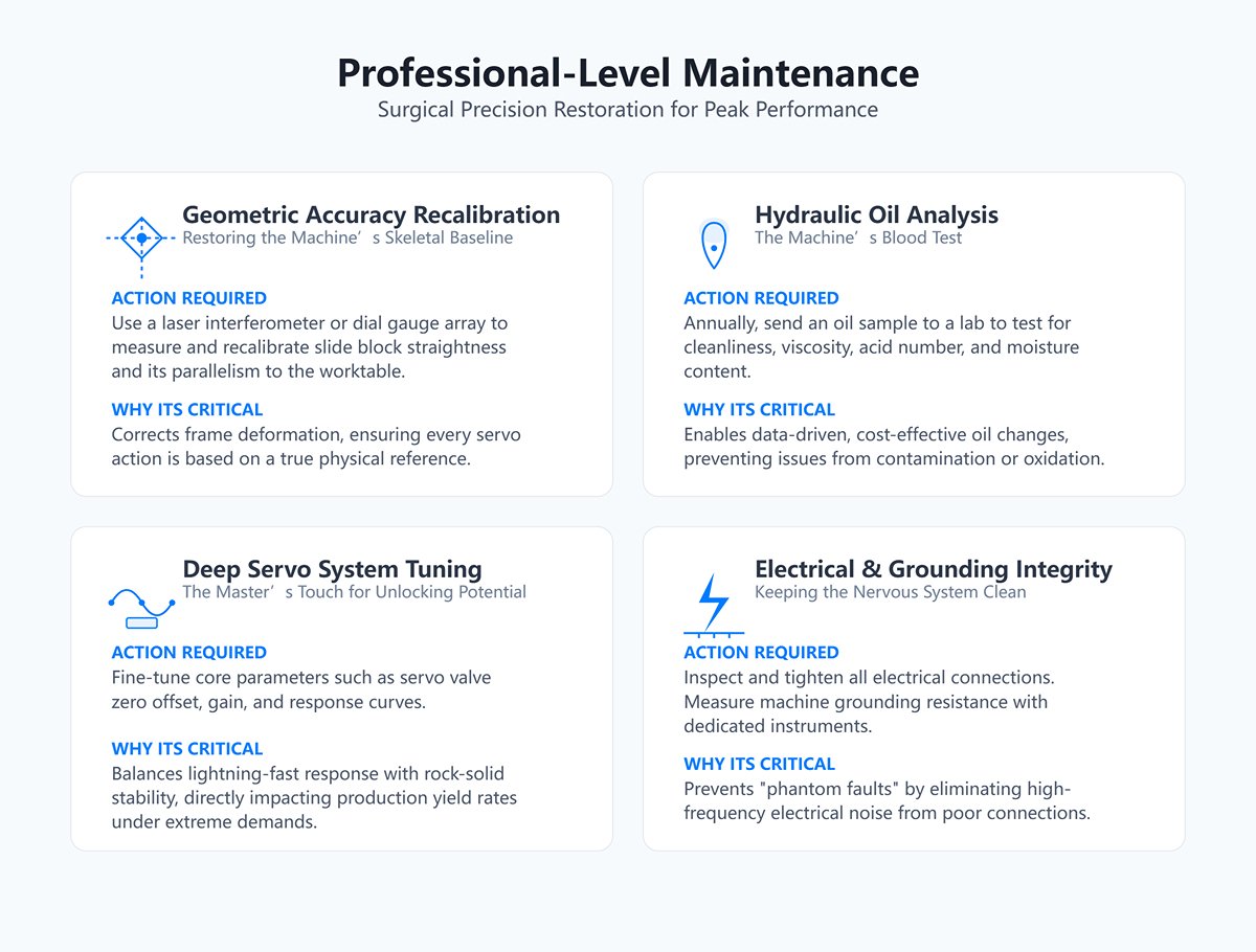
This level of maintenance must be carried out by factory-trained or highly experienced professional engineers. It goes beyond routine upkeep, involving recalibration of core precision and strategic lifecycle management of the equipment.
- Geometric Accuracy Recalibration: Restoring the Machine’s Skeletal Baseline
- Action Required: Using a laser interferometer or high-precision dial gauge array, measure and recalibrate the slide block’s straightness across its full travel and its parallelism relative to the worktable.
- Why It’s Critical: After tens of thousands of press cycles, the machine frame undergoes imperceptible stress relief and permanent deformation. Periodic geometric recalibration corrects this “skeleton,” ensuring every effort of the servo system is built on an absolutely true physical reference.
- Hydraulic Oil Analysis: The Machine’s Blood Test
- Action Required: Annually (or every 2,000–4,000 operating hours), take a hydraulic oil sample and send it to a specialized lab to test for cleanliness level (NAS rating), viscosity, acid number, and moisture content.
- Why It’s Critical: Like a full medical check-up, this reveals whether the fluid has oxidized, become contaminated, or absorbed moisture. Oil change decisions based on scientific data are far more accurate and cost-effective than relying on “gut feeling” or fixed schedules.
- Deep Servo System Tuning: The Master’s Touch for Unlocking Potential
- Action Required: Fine-tune core parameters such as servo valve zero offset, gain, and response curves.
- Why It’s Critical: This is a blend of science and artistry. Too little gain makes the system sluggish; too much causes oscillation and overshoot. A skilled engineer can find the perfect balance, enabling the press brake to combine lightning-fast response with rock-solid stability—directly impacting yield rates under extreme production demands.
- Electrical Connection and Grounding Integrity Check: Keeping the Nervous System Clean
- Action Required: Inspect and tighten all electrical connections from the CNC to the servo drive, then to the servo valve and linear scale. Use dedicated instruments to measure machine grounding resistance.
- Why It’s Critical: Often overlooked, this step can prevent countless “phantom faults.” Poor grounding or loose signal connectors can introduce high-frequency electrical noise, akin to a constant static between commander and troops, resulting in erratic, hard-to-reproduce synchronization errors.
V. Conclusion
In conclusion, understanding how a hydraulic press brake stays synchronized is fundamental to mastering precision metal forming. We've journeyed from the rigid, mechanical constraints of early torsion bar systems to the intelligent, micro-level accuracy of today's CNC electro-hydraulic servo controls.
The key takeaway is that modern synchronization is not a static feature but a dynamic, closed-loop process. It relies on a constant, high-speed dialogue between high-resolution sensors, a powerful CNC brain, and responsive servo valves to ensure absolute parallelism and perfect bends, every time.
By recognizing the importance of this system and adhering to a structured maintenance plan, manufacturers can safeguard their investment, guarantee quality, and maximize productivity. Your pursuit of bending perfection deserves a partner who understands this technology from the inside out.
At ADH, we don't just sell machines; we provide precision solutions. If you're looking to upgrade your capabilities with a new press brake, troubleshoot an existing system, or simply learn more by exploring our Brochures, we invite you to contact us. Let our experts help you achieve the next level of accuracy and efficiency.


