How does an electric press brake work?At its core, it's a story of converting electricity into precise mechanical force through a sophisticated, direct-drive system. This technology marks a pivotal shift from traditional hydraulic power, offering a leap forward in speed, accuracy, and efficiency.
This guide will demystify this process. We'll explore the servo motor "heart," the transmission "muscles," and the CNC "brain" that orchestrate every bend with micrometer-level precision. By comparing its performance against hydraulic machines and offering a practical user guide, we will provide a complete understanding of how this technology is shaping the future of metal fabrication.
I. Clearing Up the Myths: Understand Electric Press Brakes in 30 Seconds — and Why They're the Future
In the sheet metal fabrication world, while many still wrestle with the temperature fluctuations, leaks, and noise of hydraulic systems, a quiet revolution driven by electricity has already begun. The electric press brake is not merely a swap of power source — it embodies an entirely new design philosophy, relentlessly pursuing maximum efficiency and precision. With undeniable advantages, it is reshaping the future landscape of modern bending technology.
1.1 Core Definition: Electric Press Brake in a Single Sentence
An electric press brake is a fully hydraulic-free CNC forming machine that uses servo motors to directly drive precision ball screws or pulley systems, accurately converting rotational motion into the ram’s linear movement.
1.2 Value Proposition: Why Electric Press Brakes are Winning the Market
The rapid rise of electric press brakes isn’t due to a single standout feature, but rather their across-the-board superiority over traditional hydraulic machines in efficiency, precision, cost-effectiveness, and environmental impact—this is their true value.
- Exceptional Energy Efficiency: This is the most disruptive advantage. In a traditional hydraulic press brake, the pump runs continuously to maintain system pressure, even when idle, wasting substantial energy. In contrast, an electric press brake consumes energy only during the actual bending action, with near-zero draw while idle. Overall, energy consumption is typically over 50% lower than that of an equivalent servo-hydraulic press brake.
- Unmatched Production Speed: Thanks to the superb dynamic response of servo motors, the ram can achieve extremely high acceleration and deceleration, shortening cycle times. Faster approach and return speeds translate into at least 30% higher production efficiency.
- Micron-Level Accuracy: The pairing of servo motors with ball screws forms a direct-drive system that responds instantly with no delay. The CNC can precisely control ram position, speed, and torque in a closed loop, achieving repeat positioning accuracy of ±0.001 mm—a level hydraulic systems struggle to match.
- Minimal Maintenance & Eco-Friendliness: Without hydraulics, there’s no need for regular oil, filter, or seal changes, and no risk of leaks or contamination. Operating noise is extremely low, creating a quieter, cleaner workspace.
Here’s something most people don’t know (wink): Hydraulic press brakes have a hidden “warm-up” cost. Early in the day or within the first couple of hours of operation, changes in oil temperature cause bending angle drift, requiring constant compensation or resulting in scrap. Electric press brakes eliminate this entirely—their precision remains consistent from the first piece to the last. This outstanding process stability delivers hidden value far beyond the energy savings alone.
1.3 Quick Comparison: Electric vs. Hydraulic vs. Pneumatic Press Brakes
To help you quickly identify the differences between these three types of machines, here’s a clear comparison matrix:
| Feature | Electric Press Brake (Servo-Electric) | Hydraulic Press Brake | Pneumatic Press Brake |
|---|---|---|---|
| Core Drive | Servo motor + ball screw/pulley | Hydraulic pump + cylinder | Air compressor + cylinder |
| Typical Tonnage Range | Small to medium (< 200 tons) | Full range (up to 2000+ tons) | Very small (< 30 tons) |
| Energy Consumption | Very low (on-demand) | High (pump runs continuously) | Moderate |
| Production Speed | Very fast | Moderate | Fast (for thin/light materials) |
| Repeat Accuracy | Very high (micron level) | Good (servo-hydraulic) / average (torsion shaft) | Lower |
| Maintenance | Minimal (no hydraulic oil) | Complex (oil, filters, seals) | Simple |
| Operating Noise | Very quiet | Loud | Moderate (air exhaust noise) |
| Key Advantages | Speed, precision, energy savings, eco-friendly | High tonnage, mature tech, relatively lower cost | Simple design, fast (light loads) |
| Main Applications | High-precision, high-efficiency production of small/medium parts | General-purpose, ideal for thick plate or large workpieces | Quick, simple bends on thin sheet |
II. In-Depth Breakdown: How Electric Press Brakes Turn Electricity into Precision Mechanics
The electric press brake’s leap in speed and accuracy comes from replacing the complex hydraulic “pump–valve–pipe–cylinder” system with an integrated “servo motor–precision drive–closed-loop control” architecture. This is not just a change in power source—it’s a fundamental shift in control logic.
2.1 Power Core: The Servo Motor Drive System
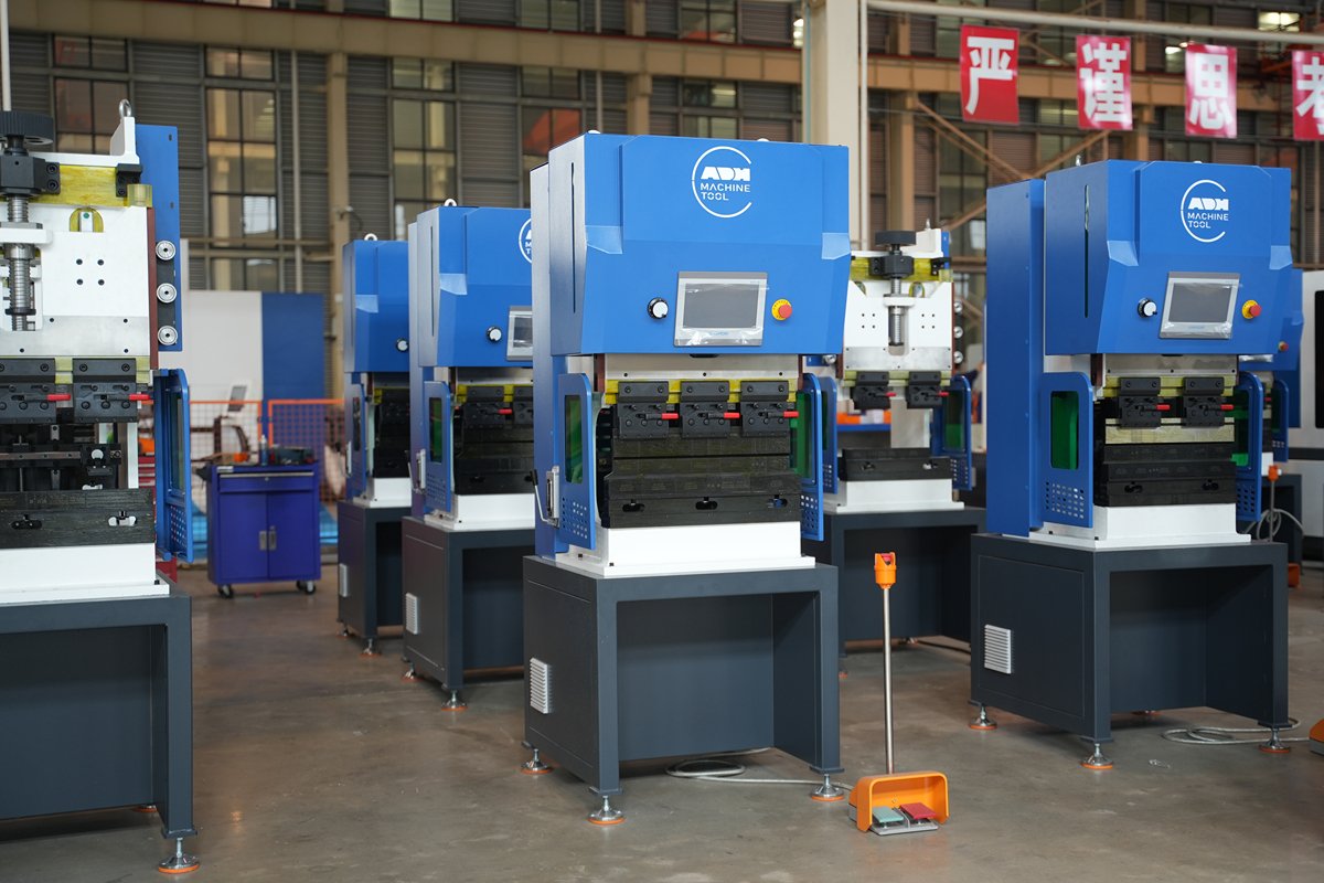
The muscle behind an electric press brake is one or more high-power AC servo motors mounted on the machine’s upper beam or C-frame. Unlike standard motors, a servo motor can precisely control position, speed, and torque—making it an “intelligent” drive unit.
Its intelligence lies in the built-in encoder. Acting like a high-precision odometer, the encoder reports the motor’s rotational position to the CNC controller in real time, down to thousandths of a revolution. This precise feedback allows the CNC to issue ultra-specific commands—such as “rotate at exactly 3000.5 RPM, turn 273.1 degrees, then stop instantly”—laying the groundwork for exact mechanical motion.
2.2 Force Transmission: Converting Rotation to Linear Motion
The servo motor delivers high-speed rotation, while bending demands strong linear downward force. Efficiently converting and amplifying this motion is the heart of electric press brake design. Two main solutions dominate today’s market:
- Ball Screw Drive: The most direct and pure method. The servo motor’s rotation is transferred via a timing belt to one or more large-diameter precision ball screws. With internal rolling steel balls minimizing friction, ball screws operate at over 95% efficiency. As the screw turns, the matching nut moves the ram smoothly and precisely up or down. This short transmission chain offers high rigidity, instant response, and exceptional accuracy—making it the preferred choice for small-to-medium high-precision press brakes.
- Belt/Pulley Amplification System: This design is more inventive and is widely used in medium- to large-tonnage servo-electric press brakes. Instead of directly driving the ram, the servo motor powers a complex multi-stage belt and pulley system that in turn drives eccentric wheels or crankshafts on either side of the ram. This setup cleverly harnesses the principles of leverage and pulley mechanical advantage. The motor only needs to rotate a small pulley, which via high-strength belts turns larger pulleys. Each stage reduces speed while multiplying torque several-fold, ultimately delivering tens or even hundreds of tons of force to the ram.
2.3 The Intelligent Brain: CNC Closed-Loop Feedback System
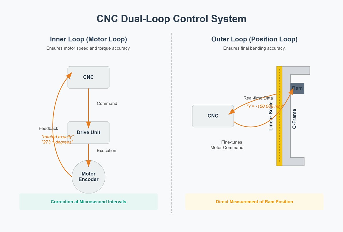
If the servo motor is the heart and the drive mechanism the skeleton, then the CNC control system serves as the intelligent brain of the machine. It employs a dual closed-loop feedback architecture to guarantee flawless results:
- Inner Loop (Motor Loop): This loop connects the CNC system to the servo motor’s drive unit. The CNC sends a command, the drive executes it, and the motor’s encoder instantly reports back (e.g., “I have rotated exactly 273.1 degrees as instructed”). The system compares and corrects at microsecond intervals, ensuring motor speed and torque remain perfectly accurate.
- Outer Loop (Position Loop): This loop is critical for final bending accuracy. A linear scale mounted on the machine’s C-frame acts like an ultra-precise caliper, directly measuring the ram’s actual position and feeding real-time data to the CNC (e.g., “Current ram position is Y = -150.002 mm”). The CNC compares this actual result to the programmed target and fine-tunes its commands to the servo motor accordingly.
This “command–execution–inner loop feedback–outer loop feedback–correction” cycle repeats thousands of times in the blink of an eye during bending, locking the ram’s motion path and final position firmly within a micron-level tolerance band, unaffected by frame deflection or other external factors.
2.4 Workflow Visualization: Four Steps to a Perfect Bend
Let’s bring these components together and see how a flawless bend is executed in an instant:
- Step One: High-Speed Approach – The CNC commands the servo motor to run at full speed, driving the ram downward from top dead center at over 200 mm/s, rapidly closing the gap to the workpiece and minimizing idle travel time.
- Step Two: Precision Bending – Just before contacting the workpiece, the CNC signals the motor to slow to the preset bending speed. With precisely controlled torque and rpm, the servo motor presses the ram smoothly to bend the sheet to the target angle. Torque control ensures optimal pressure, while position closed-loop control secures exact depth.
- Step Three: Hold and Release – Upon reaching the target depth, the servo motor can hold torque precisely, maintaining pressure to allow internal stresses in the material to dissipate and reduce springback. The CNC then commands a smooth reverse motion to release the load.
- Step Four: High-Speed Return – After bending, the CNC again orders full-speed reverse rotation, lifting the ram back to top dead center at maximum velocity, ready for the next cycle. The entire process flows seamlessly—fast, precise, and quiet.
2.5 Common Misconceptions: Debunking Three Myths About How It Works
- Myth 1: “A servo-electric press brake is just a big electric push rod.” Clarification: This is the biggest misunderstanding. The core technology isn’t about brute force—it’s about control. Converting rotary motion to linear motion is well-established, but achieving precision control over speed, position, and force within hundredths of a second, while perfectly synchronizing dual motors, is the real technical mastery. It’s more like a martial arts master attuned to minute details than a raw power lifter.
- Myth 2: “The tonnage of a servo-electric press brake is fixed.” Clarification: Quite the opposite. Thanks to precise torque control, the output tonnage is fully programmable. You can set exactly 80 tons for a particular bend based on sheet thickness and material, never applying more force than necessary. This protects tooling and saves energy. Hydraulic presses usually set a maximum pressure via a relief valve, with far less accuracy.
- Myth 3: “No oil means no maintenance.” Clarification: It’s “low maintenance,” not “maintenance-free.” While you avoid the hassles of hydraulics, the ball screws and precision guide systems still require periodic inspection and lubrication with specialized grease to maintain accuracy and longevity. Drive belts also need regular tension and wear checks. Neglecting these will still lead to precision loss and potential downtime.
III. Performance Showdown: Electric vs. Hydraulic – A Comprehensive Technological Shift
Comparing servo-electric press brakes with advanced electro-hydraulic CNC models isn’t a simple old-versus-new contest. It’s a deeper conversation about efficiency, accuracy, and the future of manufacturing costs. With their revolutionary drive systems, servo-electric machines are redefining productivity. That said, hydraulic technology remains the undisputed powerhouse in certain heavy-duty applications.
3.1 All-Dimension Performance Comparison Matrix
To make the differences crystal clear, we’ve conducted a rigorous quantitative assessment across nine critical performance dimensions:
| Performance Dimension | Servo-Electric Press Brake | CNC Hydraulic Press Brake | Analysis & Notes |
|---|---|---|---|
| Energy Efficiency | ★★★★★ (Very high) | ★★★☆☆ (Moderate) | Servo-electric machines consume power only during the actual bending moment, with extremely low standby consumption. Hydraulic pumps must run continuously to maintain pressure, typically using over 50% more energy than electric systems. |
| Production Speed (Cycles/hour) | ★★★★★ (Very fast) | ★★★☆☆ (Fast) | Servo motors respond instantly, with exceptionally high approach and return speeds (>200mm/s). Cycle times can be reduced by more than 30%, greatly improving throughput. |
| Repeat Positioning Accuracy | ★★★★★ (Exceptional, ±1–2 μm) | ★★★★☆ (High, ±5–10 μm) | Direct drive eliminates delays, achieving micron-level control. Hydraulic systems are limited by oil temperature changes and valve response times. |
| Process Stability | ★★★★★ (Exceptional) | ★★★☆☆ (Moderate) | No preheating required; angles remain consistent from the first to the last piece. Hydraulic machines are prone to angle drift from oil temperature fluctuations, requiring mid-process compensation. |
| Maximum Tonnage | ★★☆☆☆ (Limited) | ★★★★★ (Very high) | Electric models are generally under 200 tons. Hydraulic technology easily achieves thousands of tons, making it the only viable option for heavy-duty thick plate bending. |
| Maintenance Cost | ★★★★★ (Very low) | ★★☆☆☆ (High) | No hydraulic system means no oil changes, filter replacements, seal swaps, or leak management. Maintenance workload and costs are significantly reduced. |
| Initial Investment | ★★★☆☆ (High) | ★★★★☆ (Moderate) | For the same tonnage, electric press brakes generally cost more upfront than hydraulic models—especially compared to simpler torsion-bar synchronized hydraulic machines. |
| Environmental Friendliness (Noise/Cleanliness) | ★★★★★ (Excellent) | ★★★☆☆ (Average) | Extremely quiet operation (<60 dB) and oil-free. Hydraulic pumps are noisier (>75 dB) and pose oil spill and waste disposal issues. |
| Programmability (Force/Speed) | ★★★★★ (Exceptional) | ★★★★☆ (High) | Allows precise programming of speed and force throughout the bending cycle for complex forming. Hydraulic machines also offer programmability, but with slower response and less precision. |
3.2 In-Depth Insight: The Servo-Electric Press Brake as a “Productivity Multiplier,” Not Just a Substitute
If you regard a servo-electric press brake merely as a “power-saving” or “faster” version of a hydraulic unit, you’re missing its true strategic significance. It is a genuine productivity multiplier, delivering value through a powerful synergy of multiple advantages.
Overall Business Gain = (Speed Increase × Utilization Rate Increase) + (Scrap Reduction ÷ Quality Cost) − Total Lifecycle Cost
- The Multiplicative Effect of Speed: A 30% boost in cycle speed is not just about making a few hundred extra parts per day. In high-intensity, multi-batch production, it means faster order fulfillment, shorter production cycles, and the ability to seize critical market timing—a strategic edge.
- The Hidden Value Surge from Stability: This is the true “ace” of the servo-electric press brake.
- Eliminating Preheat Time: Hydraulic machines require 15–30 minutes of daily preheating before stable operation. Servo-electric models are ready to work instantly, yielding more usable production time every day and directly improving utilization.
- Eradicating Mid-Process Retuning: In hydraulic systems, rising oil temperature can alter bend angles, forcing operators to stop, test, and adjust programs repeatedly. The servo-electric’s consistent precision ensures continuous production without interruptions, eliminating hidden downtime.
- Driving Scrap Rates to the Minimum: Consistent precision translates to exceptionally low scrap rates. This not only saves material costs but also reduces labor and time spent on rework, waste handling, and quality inspections. The impact is especially significant when working with high-value materials such as stainless steel or aluminum.
Key Takeaway: Investing in a servo-electric press brake means acquiring not just a machine, but a highly predictable, consistently stable precision manufacturing unit. This level of certainty is at the heart of modern lean production.
3.3 Rational Analysis: When Hydraulic Press Brakes Remain Irreplaceable
Despite the clear advantages of servo-electric technology, hydraulic press brakes will continue to dominate in certain areas for the foreseeable future. Choosing them is not about clinging to tradition—it’s about sound engineering judgment:
- High-Tonnage, Thick Plate Heavy-Duty Work: This is the unchallenged domain of hydraulics. When bending steel plates several centimeters thick, requiring pressures of 500, 1000 tons or more, hydraulic systems remain the only mature, cost-effective solution. Electric systems face steep challenges and costs at ultra-high tonnage.
- Extremely Budget-Sensitive Scenarios: For startups or non-core bending operations, a simple torsion-bar synchronized hydraulic machine can cost as little as one-third—or less—of an equivalent-tonnage servo-electric model, offering a much lower entry barrier.
- Special Processes Requiring Extended Pressure Hold: Certain composite hot pressing or specialized forming methods demand sustained full-load pressure over long durations. Hydraulic systems can achieve this easily and efficiently via lock valves, whereas maintaining static torque at full load in a servo motor risks overheating and requires advanced cooling solutions.
- Ultra-Long Workpiece Bending: For parts spanning 6, 8, or more meters, dual-machine tandem setups are common. Mature, cost-effective hydraulic tandem solutions remain the more practical and mainstream choice.
IV. Practical Guide: Unlocking 100% of Your Servo-Electric Press Brake's Potential
Owning a state-of-the-art servo-electric press brake is only the first step toward high-efficiency, precision manufacturing. The real gains come from integrating advanced equipment with standardized workflows, refined techniques, and disciplined maintenance. This guide presents a complete “best practice” framework—from preparation to upkeep—to help you convert theoretical advantages into unmatched productivity.
4.1 Preparation Stage: Standard Operating Procedures (SOP)
Thorough preparation is the foundation of a smooth production day. In bending operations, 90% of issues stem from oversights during setup. Skipping any step can lead to multiplied costs in time and materials later.

- 1. Machine Status Check and Startup
- Environment Inspection: Walk around the machine to ensure the work area is clear of debris, verify that both upper and lower tooling are securely mounted, and confirm that the backgauge fingers are free from any obstructions.
- Power On and Homing: Switch on the main power supply and start the CNC controller. Perform the “Return to Reference Point” (Homing) procedure to allow the ram (Y-axis) and backgauge (X/R/Z axes) to automatically return to their mechanical origins. This step “wakes up” the machine and establishes an accurate coordinate system—never skip it.
- 2. Drawing and Process Review
- Carefully examine the part drawings for the day’s job, focusing on critical details: material type (e.g., mild steel, stainless steel, aluminum), sheet thickness, bend angles, internal radius, and dimensional tolerances for each bend.
- Verify the bend sequence specified in the process document. This determines your programming strategy, the backgauge movement path, and whether there’s a risk of interference with the machine or formed sections.
- 3. Tool Selection and Installation
- Select the appropriate punch (upper die) and die (lower die) based on sheet thickness, material, and bend angle. A key guideline: the die opening (V-width) is typically 6–8 times the sheet thickness for mild steel; increase slightly for stainless steel and reduce slightly for aluminum.
- Cleaning and Inspection: Before installation, wipe the die mounting and working surfaces with a clean, lint-free cloth. Check for dents, scratches, or metal debris. Even minor damage on the die will leave permanent marks on the workpiece.
- Installation and Alignment: Mount the upper and lower dies and lightly tighten. In manual mode, lower the ram slowly until the punch tip gently enters the center of the die’s V-opening. Once automatic centering is complete, fully tighten all fasteners.
4.2 Core Steps: From Programming to First-Piece Verification
This is the pivotal stage where drawings become reality. Every action directly impacts final quality and efficiency. A high-precision electric press brake demands equally precise handling.
- 1. CNC Programming
- Parameter Entry: Accurately input into the CNC controller the sheet thickness, material type (select the matching tensile strength database), and tool parameters (punch angle/radius, die V-width/angle). These values form the theoretical basis for calculating bend compensation and ram depth—one error here can cascade into many.
- Step Editing: Following the process sequence, enter each bending step’s bend length (backgauge position) and bend angle. Modern CNC systems typically offer graphical programming, allowing you to simulate the bending process directly on the touchscreen and visually check for interference.
- 2. Fine-Tuning and Simulation
- Compensation Setting: The system will automatically calculate theoretical Y-axis depth and X-axis backgauge compensation values. Experienced operators adjust these slightly based on the actual hardness and springback characteristics of the material batch.
- Dry-Run Simulation: Run the program without any sheet loaded, letting the machine go through all bending steps. This zero-cost check ensures the bend sequence is logical, confirms no backgauge interference, and validates that material handling will be smooth.
- 3. First-Piece Test Bend and Inspection
- Test Bend: Use a piece identical to the production batch material (same lot and rolling direction) for the test bend.
- Inspection: Measure each angle and dimension of the first piece precisely using a calibrated protractor and caliper.
- Scientific Adjustment: If angles or dimensions deviate, do not directly alter the absolute Y-axis or X-axis coordinates. The professional approach is to access the “Angle Compensation” or “Dimension Compensation” menu, input the current actual angle/dimension and the target values, and let the system calculate the correct compensation and update the program. This method is more accurate and allows the system to learn and refine its database.
- 4. Batch Production: Once the first-piece is confirmed accurate, lock the program and start mass production. Continue periodic sampling (e.g., every 20–50 pieces) to ensure long-term quality stability.
4.3 Maintenance: The Secret to Extending Machine Life and Precision
The “low-maintenance” nature of an electric press brake is built upon regular upkeep. Scientific maintenance is the foundation for sustaining micron-level precision over time.
- Daily Maintenance (< 5 minutes)
- After finishing work, keep the machine clean—especially the upper and lower die mounts, backgauge guide rails, and CNC touchscreen.
- Weekly Maintenance (< 15 minutes)
- Check and clean the backgauge ball screw and linear guide rails. Lubricate with the specified grease using a grease gun per manufacturer’s instructions. Dust and poor lubrication are the biggest threats to precision drive components.
- Check the drive belt tension is appropriate and inspect visually for cracks or abnormal wear.
- Check and clean the backgauge ball screw and linear guide rails. Lubricate with the specified grease using a grease gun per manufacturer’s instructions. Dust and poor lubrication are the biggest threats to precision drive components.
- Monthly Maintenance (< 30 minutes)
- Inspect and clean all cooling fan filters in the electrical cabinet to ensure unobstructed airflow. Servo drives are highly sensitive to operating temperature.
- Annual Maintenance (Professional Service)
- Contact the manufacturer or an authorized service engineer to perform a comprehensive check and calibration of the full-stroke positioning accuracy of the backgauge and the parallelism of the ram relative to the worktable.

4.4 Three Common Operational Pitfalls to Avoid
- Pitfall 1: Over-reliance on “Automatic Calculation” and skipping the first-piece test bend
- Consequence: CNC calculations are based on standard material databases. In reality, each batch may have subtle variations in thickness, hardness, and rolling direction, enough to cause a 0.5°–1° angle deviation. Skipping first-piece verification before mass production is the leading cause of large-scale scrap.
- Pitfall 2: Forcing the machine to process workpieces beyond its rated capacity
- Consequence: Every press brake has a tonnage–length load curve. Attempting to bend stock that is too thick or too long, or using an undersized V-opening, can cause continuous overload alarms in the servo motor. Forcing operation can severely damage expensive servo motors and ball screws, and may even cause permanent structural deformation of the frame, destroying precision.
- Pitfall 3: Bending heavily off-center loads without compensation
- Consequence: While electric press brakes have excellent dual-drive synchronization to resist off-center loading, bending short parts repeatedly on one side places extreme, uneven wear on that side’s screw, guide, and bearing systems. Over time, this can seriously compromise machine parallelism.
- Correct Approach: Position small parts as close to the center of the worktable as possible for bending. If the process requires off-center bending, place a “balance block” of identical thickness and length on the opposite side for a simultaneous “empty” bend, keeping loads as balanced as possible. This is a professional technique to extend precision life.
V. Conclusion
In essence, the question of how does an electric press brake work reveals a fundamental shift in manufacturing philosophy—from brute hydraulic force to intelligent, electrical precision. We've seen how this technology leverages servo motors, direct-drive systems, and sophisticated CNC controls to deliver unparalleled speed, accuracy, and efficiency.
This isn't just an alternative to hydraulic machines; it's a productivity amplifier, minimizing waste and maximizing output from the very first part to the last. While hydraulic power remains king for heavy-duty applications, the electric press brake has undeniably defined the new standard for high-performance, high-precision bending.
Ready to harness this new level of performance in your own operations? The team at ADH is at the forefront of this technology. Whether you are looking to invest in your first electric press brake or want to optimize your current fabrication processes, our experts are here to help.
You can explore our detailed product Brochures to better understand our range of solutions and technical advantages. To take the next step, contact us today to discuss your needs and discover how our advanced bending solutions can drive your business forward.


