Ⅰ. Rethinking the X-Axis: Why It’s the Hidden Champion That Determines Success
On the grand stage of laser cutting, high-powered lasers and premium cutting heads often steal the spotlight. Yet the true force behind every rapid move and precise turn is the unsung hero stretching across the machine—the hidden champion, the X-axis. Neglecting it is a primary cause of production bottlenecks, accuracy drift, and quality issues. This chapter will rebuild your understanding, showing why the X-axis’s condition directly shapes your bottom line. For those exploring advanced cutting capabilities like angled or multi-dimensional operations, check out the Complete Guide to Angled Laser Cutting to understand how axis control influences complex geometries.
1.1 Definition and Visualization: More Than Just “Left-to-Right Movement”
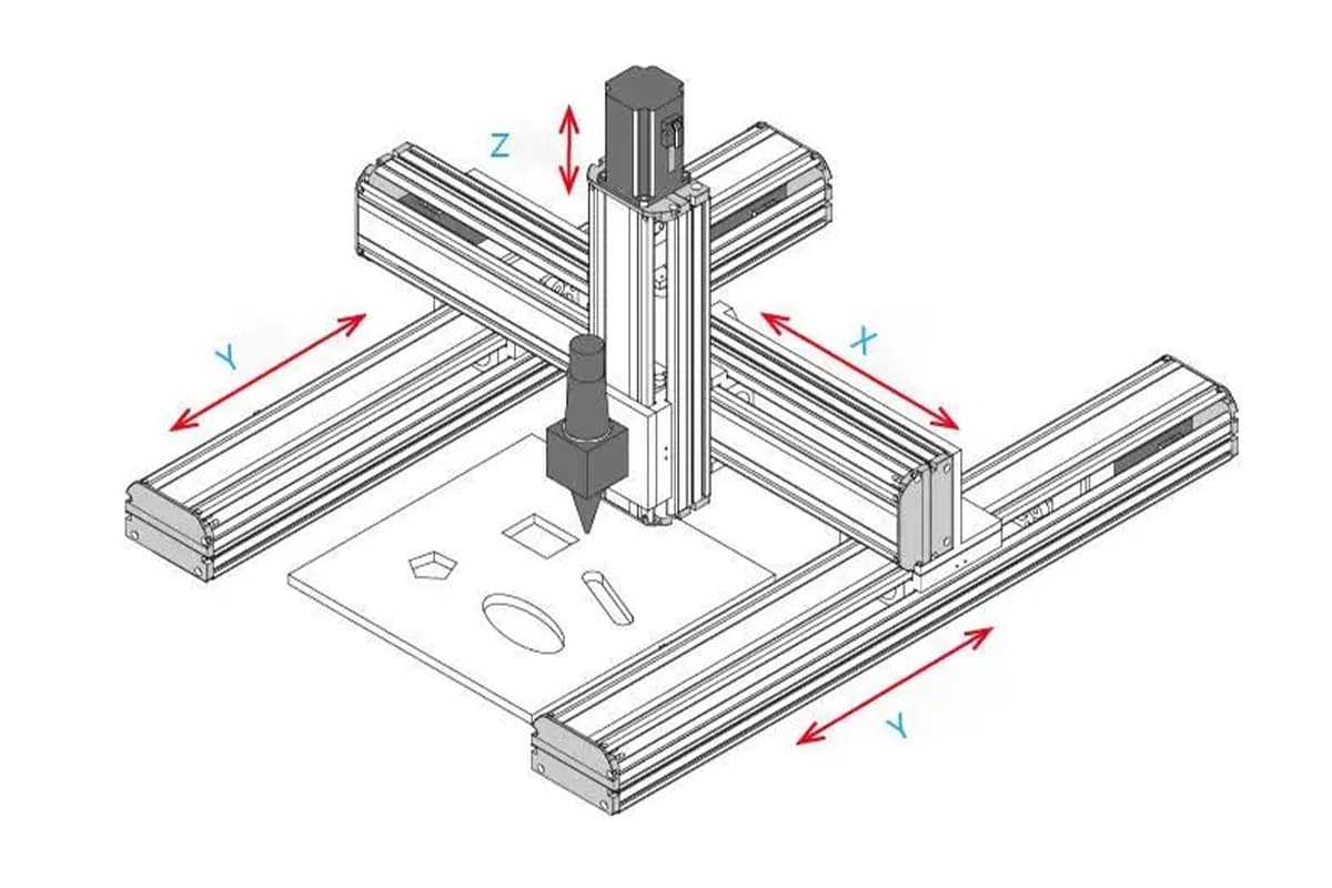
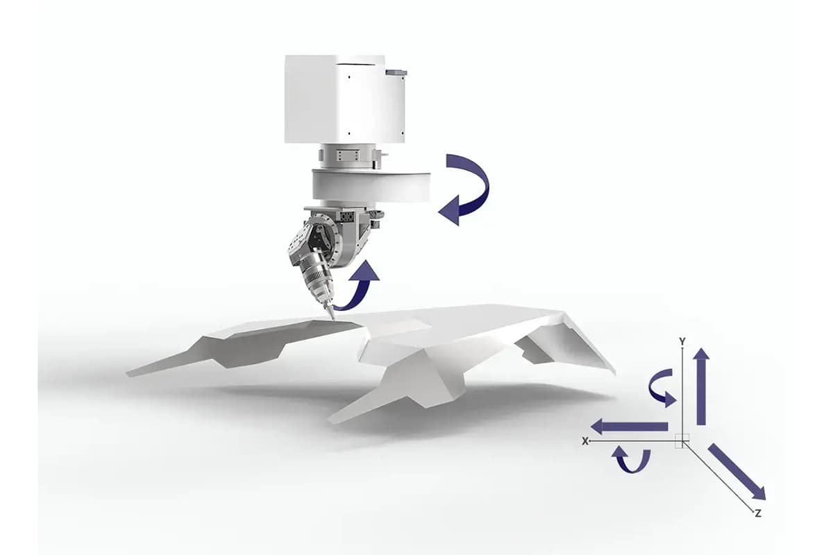
Let’s start by visualizing a clear three-dimensional coordinate system to pinpoint the X-axis precisely. In a standard gantry-style laser cutting machine, spatial movement is defined by three orthogonal axes:
- Y-axis: Typically the machine’s longest track, consisting of two heavy-duty rails and drive systems running parallel along both sides. It moves the entire gantry forward and backward.
- X-axis: This is the crossbeam mounted on the Y-axis gantry. The laser cutting head is installed on this beam and moves horizontally left and right along it.
- Z-axis: A small vertical motion unit mounted on the X-axis, which raises and lowers the cutting head to accommodate different material thicknesses and maintain optimal focus in real time.
Now, picture this visually: Imagine the laser cutter as an enormous, precision plotter. The Y-axis is like the pair of tracks that move the plotter’s arm (the gantry) forward and backward across the paper. The X-axis is the arm itself, suspended in midair. The cutting head—like a pen tip—slides left and right along this arm to execute the most intricate drawing motions.
Physically, the X-axis is a precisely engineered, high-rigidity beam, and its motion path is a perfectly straight horizontal line spanning the work area. Far from being a simple slider, it is a complex mechanical system carrying the machine’s core moving components. To understand how these components interact and influence precision, you can refer to the Guide to Laser Cutting Machines for detailed mechanical insights.
1.2 Core Functions Uncovered: How the X-Axis Defines Your Output Quality
The X-axis’s role is far more complex than the phrase “left-to-right movement” suggests. It directly governs three pillars of cutting performance:
- Foundation of Accuracy: Determines vertical line precision and faithful reproduction of complex contours — When cutting a perfect square, the horizontal sides are formed by Y-axis movement, while the vertical sides are entirely dependent on the X-axis’s precision. Any tiny gap in the X-axis drive system (backlash in belts or gear racks) can shift the start and end points of vertical lines, turning a theoretical square into a subtle parallelogram. In dense perforations or intricate patterns, such deviations accumulate and magnify, ultimately distorting the design.
- Source of Efficiency: X-axis acceleration and running speed are critical to project completion time — Cutting speed isn’t just about laser power; it hinges on the machine’s “rapid traverse speed” and “contour acceleration.” As the primary carrier of the cutting head, the X-axis’s weight, rigidity, and drive performance set the ceiling for acceleration. Insider insight: High “maximum speed” often looks great in brochures, but high acceleration is the real key to productivity. With countless short segments and curves to cut, the head must accelerate and decelerate constantly. A high-acceleration X-axis can execute these moves in quick bursts, delivering far better throughput than a machine with high speed but average acceleration. That’s why two machines both rated at 120 m/min can differ in actual job time by over 30% when cutting the same complex part.
- Soul of Quality: How stability affects edge smoothness, preventing ripples and jagged cuts — At extreme speeds and accelerations, the crossbeam can behave like a ruler being shaken rapidly, introducing slight flex and vibration.
- Beam Rigidity: If the X-axis beam lacks stiffness—such as when low-cost, lightweight extruded aluminum is used—it will vibrate during fast moves and sharp turns. These vibrations transfer directly to the cutting head, leaving fine, regular ripples along the cut edge.
- Smooth Drive: If the drive system (motor and transmission components) is not well-matched or suffers from mechanical resonance, it can produce visible jagged edges.
This explains why top-tier machines invest in aerospace-grade cast aluminum or even heavy welded steel for the X-axis beam—to achieve maximum dynamic stiffness and vibration suppression, ensuring mirror-smooth edges at any speed.
1.3 Warning: The “Ripple Effect” of an Unbalanced Axis
Ignoring the X-axis’s condition over time inevitably triggers a chain reaction of costly consequences—from the shop floor to the customer.
- Case Snapshot: How a subtle X-axis vibration ruined an entire batch and delayed delivery — A manufacturer of precision metal shields for the electronics sector discovered that a batch of parts developed faint, regular stripes along the edges after final electrophoretic coating. The whole high-value batch was rejected outright. After days of downtime, the root cause was traced to the laser cutter’s X-axis: a fastening screw on a drive gear had loosened ever so slightly. This caused high-frequency vibrations undetectable by ear, leaving faint ripple marks on stainless steel edges. Invisible on raw material, these marks became glaring after the coating—thanks to its magnifying effect.
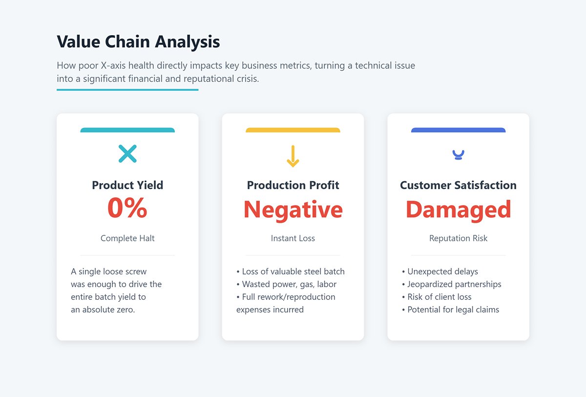
- Value Chain Analysis: Linking X-axis health directly to yield rate, profit, and customer satisfaction — This case shows that X-axis health is not an isolated technical parameter but a lifeline running through the entire production chain.
- Product Yield: In the case above, a single loose screw drove the yield rate to zero.
- Production Profit: The company lost an entire batch of valuable stainless steel, along with all invested processing costs—power, gas, labor—and faced rework or full reproduction expenses. The profit on that order vanished instantly, even turning negative.
- Customer Satisfaction: The unexpected delay damaged the company’s reputation, risked client loss, and opened the door to potential claims—jeopardizing long-term partnerships.
The takeaway is clear: X-axis stability is the cornerstone of both profitability and customer trust. Mastering its maintenance and optimization marks the transition from operator to true technical expert.
Definition of the laser cutting machine X-Axis
The X-axis refers to the horizontal movement of the cutting head or the worktable. This axis is responsible for moving the laser beam along the horizontal plane, enabling it to traverse the width of the material being cut. The movement along the X-axis is controlled by the CNC (Computer Numerical Control) system, which ensures precise positioning and consistent motion.
Importance of the X-Axis
The X-axis is crucial for several reasons:
- Precision: Precise control of the X-axis ensures that the laser beam can follow intricate patterns and designs accurately. This precision is essential for achieving high-quality cuts with minimal deviation from the desired dimensions.
- Speed: The speed at which the X-axis can move affects the overall cutting speed of the machine. Faster X-axis movement translates to quicker cutting times, which is beneficial for high-volume production environments.
- Versatility: The ability to move the cutting head or worktable along the X-axis allows the machine to handle various material sizes and shapes, enhancing its versatility in different applications.
Interaction with Y and Z Axes
In addition to the X-axis, laser cutting machines typically have Y and Z axes, each contributing to the machine's overall functionality:
- Y-Axis: Controls the vertical movement of the cutting head or worktable, allowing the laser beam to traverse the length of the material. Coordinated movement between the X and Y axes enables the laser to cut complex shapes and patterns.
- Z-Axis: Adjusts the height of the cutting head relative to the material surface. Proper Z-axis control is crucial for maintaining the correct focal distance of the laser beam, which directly impacts the quality and precision of the cut.
Types of Laser Cutting Machines and X-Axis Configurations
Different types of laser cutting machines may have unique X-axis configurations. Here are some common types:
- CO2 Lasers: These machines use a gas mixture to generate the laser beam. The X-axis in CO2 lasers is typically robust and designed to handle the larger size and weight of the cutting head.
- Fiber Lasers: Utilize a solid-state laser source, which is more compact and efficient. The X-axis in fiber lasers often benefits from advanced motion control systems for higher precision.
- Crystal Lasers: Employ crystals like Nd:YAG to produce the laser beam. The X-axis mechanisms in these machines are usually designed for high precision and stability, catering to detailed and delicate cuts.
II. How the X-Axis Works in Laser Cutting Machines
Movement Mechanics
The X-axis in laser cutting machines can be driven by different mechanisms, each offering unique benefits and suited for specific applications. The two most common types are ball screw drives and belt drives.
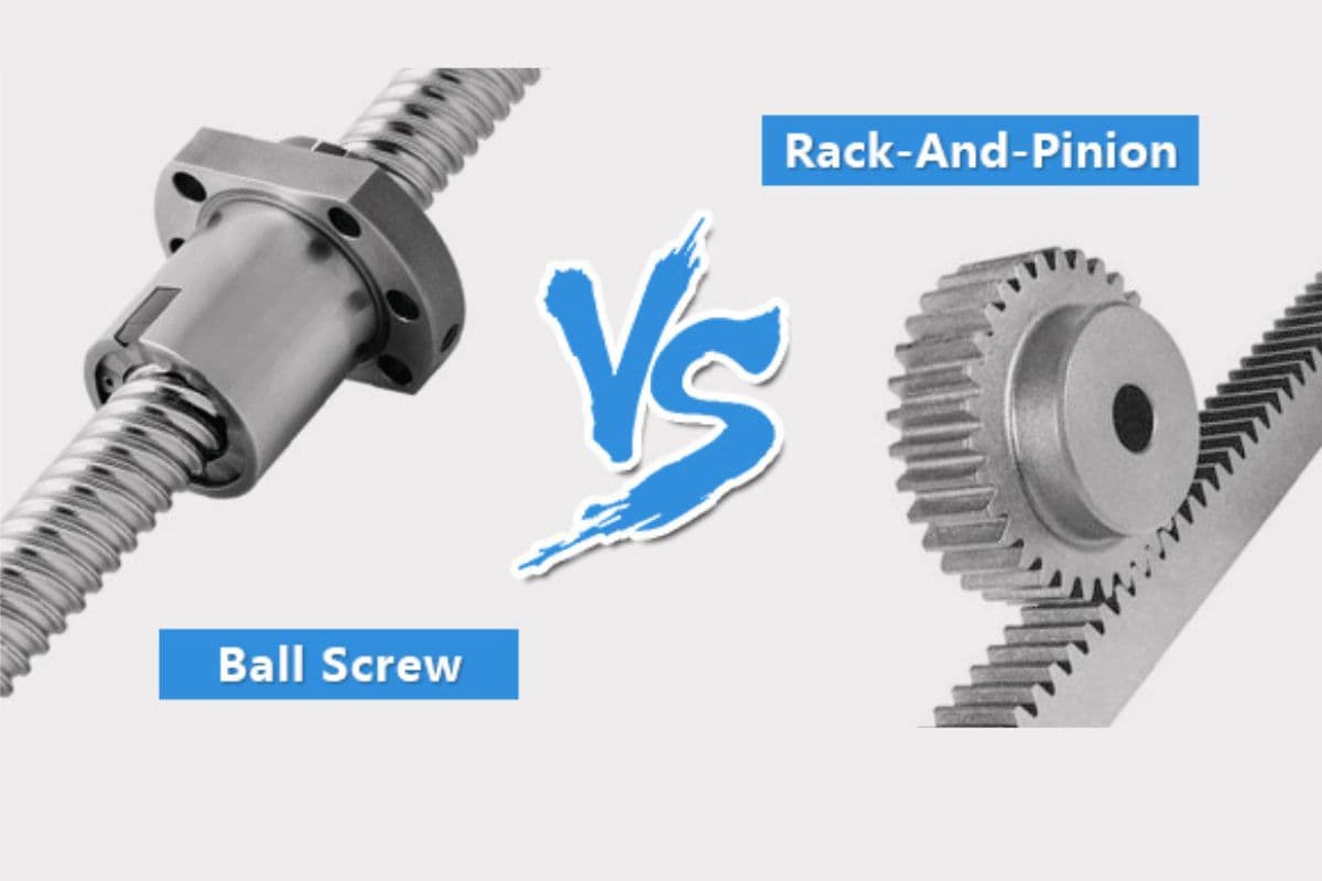
Ball Screw Drives
Ball screw drives are known for their high precision and load-carrying capabilities. They consist of a screw shaft and a ball nut, with ball bearings recirculating to reduce friction. This mechanism ensures smooth and accurate movement, making it ideal for applications requiring high precision. For instance, in the aerospace industry, ball screw drives are often preferred due to their high precision requirements.
- Advantages: High accuracy, low friction, long lifespan.
- Disadvantages: Higher cost, more complex maintenance.
Belt Drives
Belt drives use a toothed belt and pulleys to transfer motion. They are generally faster than ball screw drives but may offer slightly lower precision. Belt drives are suitable for applications where speed is a priority, and ultra-high precision is not as critical.
- Advantages: High speed, cost-effective, easy maintenance.
- Disadvantages: Potential for slippage, lower precision compared to ball screws.
Position Feedback and Correction
To ensure accuracy, encoders play a critical role in providing real-time feedback on the position of the laser head. As the servo motor drives the movement, the encoder continuously sends data back to the control system. This feedback loop enables the system to make immediate adjustments, correcting any deviations and ensuring the laser head remains on the programmed path.
The encoder's ability to detect minute changes in position is crucial for maintaining tight tolerances, especially in intricate cutting tasks. The feedback mechanism also helps in identifying and compensating for any backlash or mechanical wear in the rack and pinion or ball screw systems.
Synchronized Operation
Effective cutting requires the X-axis to work in harmony with other axes (such as Y and Z). The synchronization is managed by the machine’s control system, which coordinates the movements across all axes to follow the intended cutting trajectory accurately. This coordination is vital for complex patterns and three-dimensional cuts, where any discrepancy can lead to errors.
Dynamic Adjustment and Control
Modern laser cutting machines are equipped with advanced control interfaces that feature dynamic adjustment capabilities. These systems can respond to varying material properties, thickness, and thermal effects during cutting. For instance, the control system can modify the speed of the X-axis movement based on feedback about material resistance and laser power requirements, ensuring consistent cutting quality.
III. System Anatomy: A Precision Mechanical Journey from Drive Motor to Laser Head
To truly master the X-axis, you must think like a seasoned machinist—delving deep inside to understand the precise interplay of each component and how power flows through the system. Building on the broader perspective we established earlier, this chapter takes you on an in-depth "precision mechanics journey," breaking down the X-axis assembly piece by piece so that abstract principles become tangible realities.
3.1 Core Components Breakdown: A Single Diagram to Grasp the X-axis Structure
Picture the entire X-axis assembly exploded in mid-air—the intricate network of parts working together becomes instantly clear. It consists of several core components that operate in perfect synchrony:
- Power Core (Drive Motor): The source of all motion, responsible for delivering precise rotational power.
- Stepper Motor: Moves in discrete “steps” by responding to pulse signals. Its advantages are low cost and simple control, making it common in entry-level or desktop devices. Its critical weakness is that it operates in an “open-loop” mode—executing commands without confirming if it reached the intended position. Under excessive load, it can “lose steps,” permanently compromising accuracy.
- Servo Motor: A “closed-loop” system incorporating an encoder to provide real-time feedback on exact position and speed to the controller. If any deviation occurs, the system instantly issues corrective commands. Benefits include exceptionally high precision, rapid response, strong torque, and zero risk of losing steps. It’s safe to say that all industrial-grade laser cutters use servo motors as the driving core of the X-axis.
- Bridge of Power (Transmission System): Its mission is to transform the drive motor’s rotational output into precise, efficient linear movement of the cutting head along the X-axis. This is the second key factor determining the axis’ accuracy and speed, with specific configurations detailed in the next section.
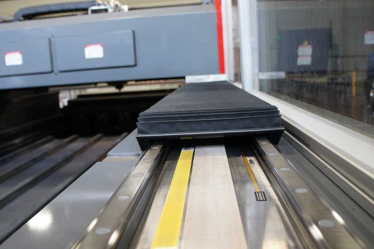
- Spine of Stability (Linear Guide Rails & Carriages): The steel backbone ensuring the cutting head’s path remains perfectly straight. Typically, one or two ultra-precision-ground rails are mounted on the X-axis beam, with the cutting head firmly secured via one or more carriages containing rolling steel balls. Rail accuracy grades (commonly H or P) and brands (such as Taiwan’s HIWIN or Japan’s THK) are critical indicators of a machine’s quality and durability.
- Rigid Backbone (Gantry Beam): The physical structure of the X-axis that supports all other components. Its key performance measure is “dynamic rigidity”—the ability to resist bending and vibration during rapid acceleration or deceleration.
- Insider Insight: Beam material and internal design directly impact cutting quality. Lower-end machines often use extruded aluminum profiles—lightweight but lacking rigidity, prone to resonance during high-speed turns, which can leave ripples along cut edges. Mid-to-high-end models commonly use aerospace-grade cast aluminum, molded in one piece with internal reinforcement ribs to achieve an optimal balance of light weight and rigidity. Top-tier machines may feature heavy-duty steel beams assembled by sectional welding, followed by rigorous stress-relief annealing to deliver unmatched rigidity, enabling extreme acceleration while maintaining mirror-like cutting precision even under the harshest conditions.

3.2 Transmission Technology Face-Off: Which X-axis Best Fits Your Needs?
The method of delivering motor power to the cutting head comes in four primary forms, each defining the machine’s cost, performance ceiling, and ideal application scenarios.
| Transmission Method | Precision | Speed | Acceleration | Load Capacity | Cost | Core Strengths | Key Weaknesses & Typical Applications |
|---|---|---|---|---|---|---|---|
| Belt Drive | Medium-Low | High | Medium | Low | Very Low | Simple structure, extremely low cost, quiet operation | Prone to stretching and wear, short lifespan, precision degrades over time. Common in non-metal engravers or hobby-grade devices. |
| Ball Screw | Very High | Medium | Medium | High | Medium | Exceptional positioning accuracy, zero backlash, smooth motion | Limited length, susceptible to “whip” vibration at high speeds, complex maintenance. Ideal for small-format, high-precision work. |
| Rack & Pinion | High | Very High | High | Very High | High | Unlimited travel length, fast speed, robust durability, handles high acceleration | Theoretical backlash (can be mitigated in high-end designs), slightly noisier. Dominant choice for industrial large-format laser cutters. |
| Linear Motor | Top-tier | Top-tier | Top-tier | High | Extremely High | Unmatched precision and responsiveness, no mechanical contact or wear | Extremely expensive, highly sensitive to metal dust, requires exceptional environmental protection. Used in elite precision manufacturing. |
In-depth Analysis & Selection Wisdom:
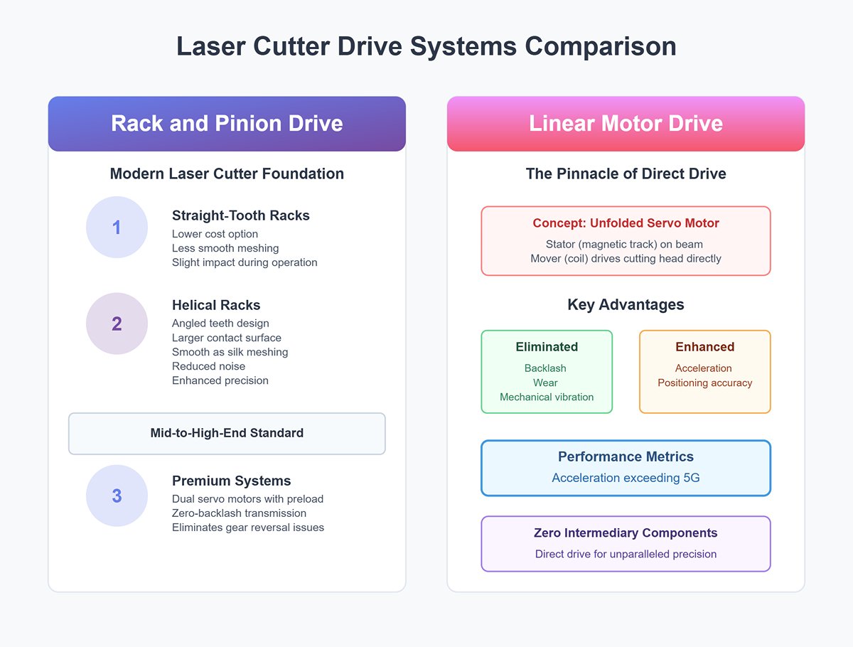
- Rack and Pinion Drive: A cornerstone for understanding modern laser cutters.
- Insider Insight: Racks come in different grades. Straight-tooth racks are cheaper but less smooth during gear meshing, causing slight impacts. Helical racks, with angled teeth, have larger contact surfaces and mesh as smoothly as silk, reducing noise and boosting precision—standard in mid-to-high-end machines. To eliminate backlash during gear reversal, premium systems employ dual servo motors with preload for truly zero-backlash transmission.
- Linear Motor Drive: The pinnacle of “direct drive” technology. Imagine a servo motor unfolded and laid flat—its stator (magnetic track) installed along the beam, and its mover (coil) driving the cutting head directly. This removes all intermediary transmission components, eliminating backlash, wear, and mechanical vibration, while delivering acceleration exceeding 5G and unparalleled positioning accuracy.
3.3 The Brain Behind the Scenes: How the Control System Commands the X-axis
If the motor and transmission system are the X-axis’ “limbs and muscles,” the control system is its “brain and nervous system,” issuing precise commands.
- Driver: The neural hub connecting brain to muscle. It converts faint digital signals from the control card (e.g., “move right by 100 pulses”) into amplified, high-voltage currents capable of powering the servo motor’s rotation. A high-performance driver executes commands more swiftly and smoothly, directly influencing the motor’s dynamic responsiveness.
- Controller Firmware: The soul that defines the X-axis’ dynamic behavior. Motion control algorithms within the firmware determine critical parameters that shape cutting quality and efficiency:
- Acceleration: Dictates how quickly the X-axis reaches top speed from a standstill. This is a core factor in real-world productivity when cutting numerous short segments or intricate designs.
- Jerk/Jolt: This is essentially the "rate of change of acceleration." Put simply, it determines how smoothly the machine starts, stops, or navigates corners. A high jerk value makes movements sharp and fast but increases impact forces, which can trigger mechanical vibrations. Too low, and movements become sluggish, reducing efficiency. Striking the perfect balance between structural rigidity and jerk settings is a hallmark of top-tier manufacturing craftsmanship.
3.4 Clearing Up Common Misconceptions
- Misconception 1: Focusing solely on the motor brand while ignoring the drive train and mechanical structure. Reality: A motor’s performance is just one slat in the barrel. A loose timing pulley, worn guide rail, or a crossbeam lacking rigidity can easily negate the advantages of a premium servo motor. Mechanical precision is always the foundation for electrical precision. The overall performance is limited by the weakest component.
- Misconception 2: Thinking the X-axis moves independently, overlooking its precision coordination with the Y-axis. Reality: The X-axis crossbeam sits on the Y-axis guide rails. If the X-axis crossbeam and both Y-axis guide rails are not kept at an exact 90° angle, every rectangle you cut will turn into a slight parallelogram, and every circle will become an ellipse. This issue, known as “gantry squareness error,” is a key indicator of assembly craftsmanship and long-term stability, and a frequent source of accuracy problems.
- Misconception 3: Chasing maximum speed without matching acceleration to structural rigidity. Reality: As mentioned earlier, the top speed of 120 m/min is rarely reached when cutting complex parts. The real efficiency driver is acceleration. Supporting high acceleration requires a rigid crossbeam and a high-response servo system. These three form a matched "performance triangle." A machine with 2G acceleration and a robust crossbeam will outperform one with a higher nominal speed but only 1G acceleration and a flimsy crossbeam.
IV. X-Axis Specifications and Performance
Key specifications
- Travel range:
- Typical values range from 800mm to 3000mm for the X-axis.
- Significance: Larger travel ranges allow for cutting larger workpieces or multiple smaller pieces in a single setup.
- Maximum speed:
- Typical values range from 50 m/min to 60 m/min.
- Significance: Higher speeds enable faster production times, especially for long straight cuts.
- Acceleration rates:
- Typical values range from 8 m/s² to 10 m/s².
- Significance: Higher acceleration rates allow for quicker changes in direction, improving overall cutting speed for complex shapes.
- Positioning accuracy and repeatability:
- Typical values range from ±0.015mm to ±0.08mm.
- Significance: Higher accuracy ensures precise cuts, critical for industries like aerospace and medical device manufacturing.
Speed and Precision Parameters
Several key parameters define the speed and precision of the X-axis in laser cutting machines. Understanding these parameters helps in selecting the right machine for specific applications and optimizing its performance.
Speed
The speed of the X-axis movement directly affects the cutting speed of the laser cutting machine. Higher speeds are desirable for increasing productivity, especially in high-volume production environments.
- Maximum Speed: Typically measured in meters per minute (m/min) or inches per second (ips). High-end machines can achieve speeds of up to 120 m/min or more.
- Acceleration/Deceleration: The rate at which the X-axis can accelerate or decelerate affects the overall cycle time and cutting efficiency. Rapid acceleration is crucial for maintaining high speeds during intricate cutting paths.
Precision
Precision is critical for achieving high-quality cuts with minimal deviation from the desired dimensions. Several factors influence the precision of the X-axis:
- Positioning Accuracy: The ability of the X-axis to reach a specified position within a minimal deviation, typically measured in micrometers (µm). High-precision machines can achieve positioning accuracy within ±10 µm.
- Repeatability: The ability of the X-axis to return to a specific position repeatedly, crucial for consistent cutting quality. Repeatability is also measured in micrometers.
- Resolution: The smallest increment that the X-axis can move, affecting the level of detail that can be achieved in the cut. High-resolution systems can achieve increments as small as 1 µm.
Factors Affecting X-Axis Performance
Several factors can impact the performance of the X-axis in laser cutting machines. Understanding these factors is essential for maintaining optimal operation and achieving the desired cutting quality.
Mechanical Factors
- Alignment: Proper alignment of the X-axis components is crucial for maintaining precision. Misalignment can lead to inaccuracies and uneven cuts.
- Wear and Tear: Over time, mechanical components such as bearings, belts, and screws can wear out, affecting the X-axis's performance. Regular maintenance and timely replacement of worn parts are essential.
- Vibration: Excessive vibration can negatively impact the precision of the X-axis. Ensuring a stable and vibration-free operation environment helps maintain accuracy.
Environmental Factors
- Temperature: Extreme temperatures can affect the materials and components of the X-axis, leading to thermal expansion or contraction. Maintaining a controlled temperature environment is important for consistent performance.
- Dust and Debris: Accumulation of dust and debris can interfere with the smooth operation of the X-axis. Proper cleaning and use of protective covers can mitigate this issue.
Software and Firmware
- CNC Control System: Computer Numerical Control (CNC) systems play a crucial role in the X-axis's performance. Advanced software with features like adaptive control and real-time feedback can enhance precision and speed.
- Firmware Updates: Regular updates to the machine's firmware can improve the performance of the X-axis by addressing bugs and implementing new features or optimizations.

V. Common Issues with the X-Axis
The X-axis in laser cutting machines is crucial for ensuring precision and efficiency in cutting operations. However, various issues can arise, affecting its performance and the overall quality of the cut.
Misalignment and Calibration Issues
Causes of Misalignment
Misalignment of the X-axis can result from several factors, including:
- Mechanical Impact: Sudden impacts or collisions during operation can cause the X-axis components to become misaligned.
- Improper Installation: Incorrect installation or assembly of the X-axis components can lead to initial misalignment.
- Thermal Expansion: Temperature fluctuations can cause the materials to expand or contract, leading to misalignment over time.
Effects of Misalignment
Misalignment can have several detrimental effects on the performance of the laser cutting machine:
- Inaccurate Cuts: Misalignment can cause the laser beam to deviate from its intended path. This results in cuts that lack precision.
- Inconsistent Quality: The quality of the cut can vary, leading to inconsistencies in the final product.
- Increased Wear: Misaligned components can experience uneven wear, reducing their lifespan and leading to frequent maintenance needs.
Calibration Solutions
Regular calibration of the X-axis is essential to maintain its alignment and ensure precise cutting. Calibration involves:
- Using Alignment Tools: Calibration involves using alignment tools such as dial indicators, laser alignment systems, and straightedges.
- Software Calibration: Many CNC systems offer software-based calibration routines that can adjust the X-axis alignment automatically.
- Routine Checks: Regularly checking the alignment and making necessary adjustments can prevent long-term misalignment issues.
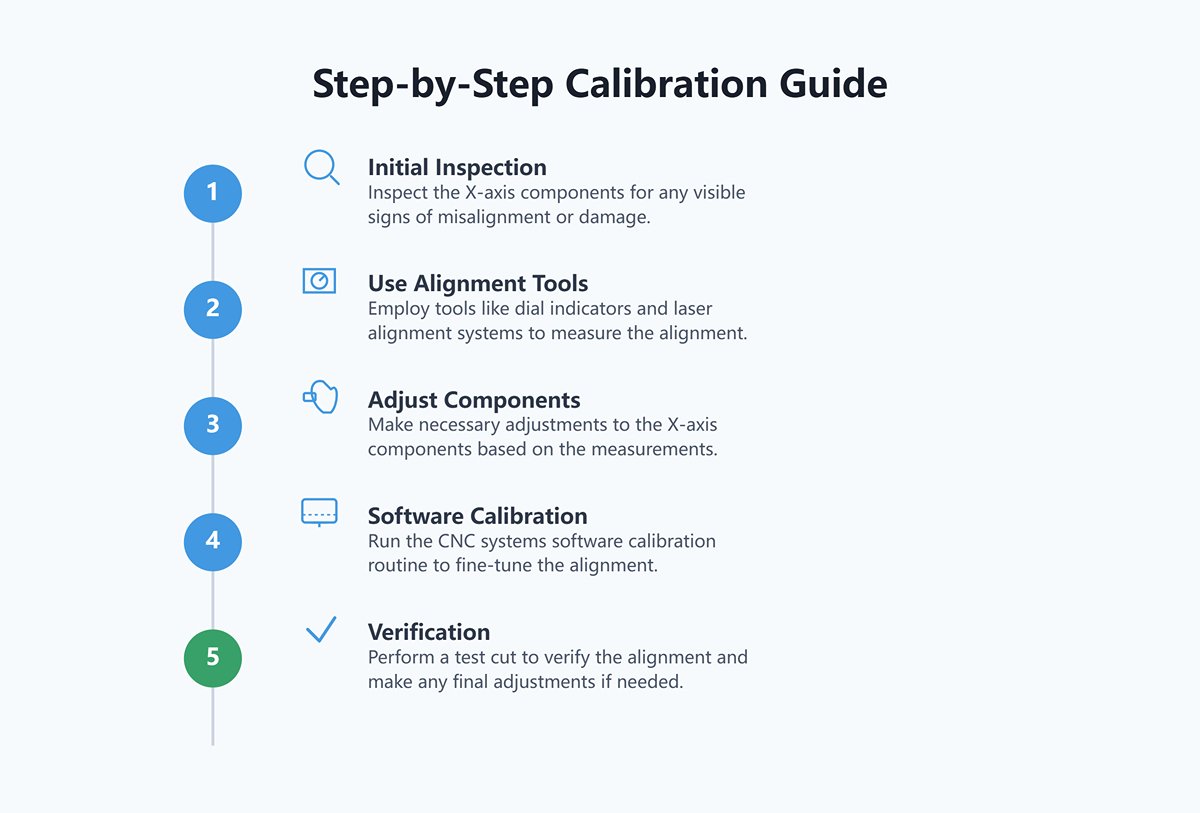
Step-by-Step Calibration Guide:
- Initial Inspection: Inspect the X-axis components for any visible signs of misalignment or damage.
- Use Alignment Tools: Employ tools like dial indicators and laser alignment systems to measure the alignment.
- Adjust Components: Make necessary adjustments to the X-axis components based on the measurements.
- Software Calibration: Run the CNC system's software calibration routine to fine-tune the alignment.
- Verification: Perform a test cut to verify the alignment and make any final adjustments if needed.
Wear and Tear on Mechanical Parts
Common Wear Components
Several mechanical parts of the X-axis are susceptible to wear and tear, including:
- Ball Screws and Bearings: High-precision components like ball screws and bearings can wear out due to continuous use. Studies show that the average lifespan of ball screws can range from 3 to 5 years, depending on usage and maintenance.
- Belts and Pulleys: In belt-driven systems, the belts and pulleys can become worn or stretched, affecting the X-axis performance.
- Linear Guides: Linear guides that facilitate smooth movement along the X-axis can accumulate debris and wear out over time.
Signs of Wear
Identifying signs of wear early can help prevent more significant issues. Common indicators include:
- Increased Friction: Excessive friction during movement can indicate worn-out bearings or ball screws.
- Slippage: In belt-driven systems, slippage of the belt can be a sign of wear.
- Unusual Noises: Grinding or squeaking noises during X-axis movement may indicate component wear.
Maintenance and Replacement
Regular maintenance and timely replacement of worn-out parts are crucial to maintaining the X-axis performance:
- Lubrication: Proper lubrication of moving parts can reduce friction and wear. Industry standards recommend lubricating ball screws and linear guides every 200 hours of operation.
- Inspection: Routine inspection of components like ball screws, bearings, belts, and linear guides—such as checking for play in ball screws or discoloration in belts—can help identify wear early.
- Replacement: Replacing worn-out parts promptly can prevent more severe issues and ensure consistent performance.
Software and Firmware Problems
Common Software Issues
Software and firmware control the precise movement of the X-axis. However, several issues can arise:
- Outdated Software: Using outdated software or firmware can lead to compatibility issues and affect the performance of the X-axis.
- Configuration Errors: Incorrect configuration settings can result in improper X-axis movement and inaccurate cuts.
- Software Bugs: Bugs in the software can cause erratic behavior or crashes, affecting the X-axis control.
Diagnosing Software Problems
Diagnosing software-related issues involves:
- Error Logs: Checking error logs and diagnostic reports can help identify software issues.
- Firmware Updates: Regularly updating the firmware can resolve bugs and improve performance.
- Configuration Review: Reviewing and correcting configuration settings can ensure proper X-axis movement.
Solutions and Best Practices
To mitigate software and firmware problems, follow these best practices:
- Regular Updates: Keep the software and firmware up to date by following the manufacturer's update instructions to benefit from the latest features and bug fixes.
- Proper Configuration: Ensure that the configuration settings are correctly set up for the specific laser cutting machine.
- Backup and Restore: Regularly backup the software and configuration settings to quickly restore the system in case of issues.
VI. Practical Applications of Laser Cutting with X-Axis
Industry-Specific Examples
Automotive Industry
In the automotive sector, laser cutting with advanced X-axis technology is employed for manufacturing complex components with high precision. Key applications include:
- Body Panels: BMW uses laser cutting with advanced X-axis systems to produce lightweight, high-strength aluminum body panels for their electric vehicles. This enhances both performance and efficiency.
- Chassis Components: Laser cutting with precise X-axis control ensures accurate cutting of chassis components, maintaining proper fit and structural integrity.
- Interior Trim: Detailed interior trim pieces, such as dashboards and door panels, are crafted using laser cutting technology for superior precision.
Example: Tesla integrated linear motor drives on the X-axis of their laser cutting machines, resulting in a 15% improvement in positioning accuracy and a 20% increase in cutting speed. This enhanced precision ensured that the body panels fit perfectly, reducing assembly time and improving production throughput.
Aerospace Industry
The aerospace industry demands stringent precision and quality standards, making laser cutting with sophisticated X-axis mechanisms ideal for various applications:
- Turbine Blades: High-precision X-axis control ensures the accurate cutting of turbine blades, critical for engine performance.
- Structural Components: Laser cutting is used to manufacture structural components with complex geometries, maintaining tight tolerances.
- Sheet Metal Fabrication: Aerospace manufacturers rely on laser cutting for fabricating sheet metal parts used in aircraft assemblies.
Example: Boeing employs laser cutting technology with advanced X-axis systems to produce titanium components for their aircraft. This results in high precision and reduced material waste, meeting the stringent standards of the aerospace industry.
Medical Devices
In the medical device industry, laser cutting with precise X-axis control is essential for manufacturing intricate and delicate components:
- Surgical Instruments: Laser cutting creates fine, precise surgical instruments with minimal burrs or imperfections.
- Implants: The X-axis ensures accurate cutting of implants, such as stents, ensuring proper fit and functionality.
- Diagnostic Equipment: Laser cutting is used for producing components of diagnostic equipment, requiring high precision and reliability.
Example: Medtronic uses laser cutting with advanced X-axis mechanisms to manufacture stents with intricate patterns. This ensures patient safety and product efficacy by maintaining high precision and quality standards.
Case Studies Showcasing X-Axis Performance
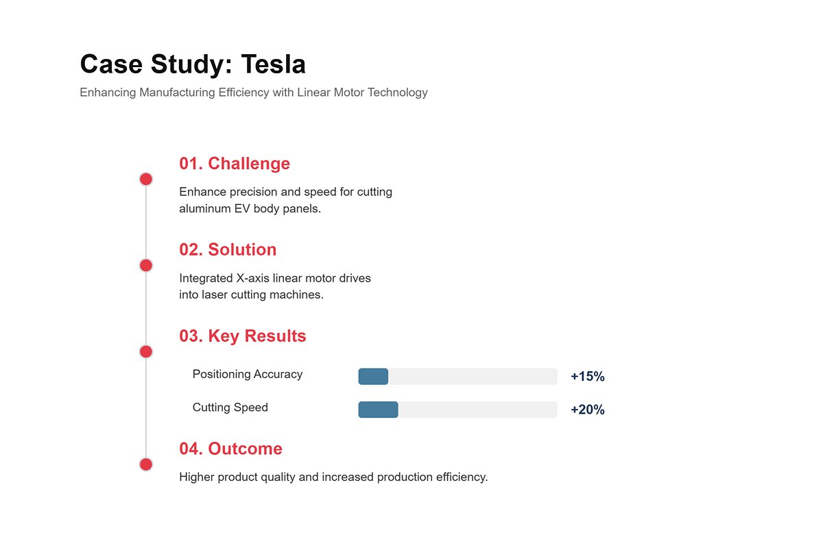
Automotive Manufacturing: Tesla
Scenario: Tesla needed to enhance the precision and speed of cutting aluminum body panels for their electric vehicles.
Solution: Tesla integrated linear motor drives on the X-axis of their laser cutting machines, resulting in:
- 15% Improvement in Positioning Accuracy: Enhanced precision ensured that the body panels fit perfectly, reducing assembly time.
- 20% Increase in Cutting Speed: Faster cutting speeds improved production throughput, meeting high demand.
Outcome: Tesla's investment in advanced X-axis technology resulted in higher-quality products and increased production efficiency, contributing to their market success.
Aerospace Manufacturing: Lockheed Martin
Scenario: Lockheed Martin required precise cutting of titanium structural components for their fighter jets.
Solution: The company implemented AI-driven adaptive control on the X-axis of their laser cutting machines, leading to:
- 25% Increase in Cutting Precision: Continuous adjustments improved the accuracy of cuts, meeting stringent aerospace standards.
- 15% Reduction in Material Waste: Optimized cutting paths reduced material waste, decreasing production costs.
Outcome: The adoption of advanced X-axis technology enabled Lockheed Martin to produce high-quality components efficiently, maintaining their competitive edge in the aerospace industry.
VII. Frequently Asked Questions
1. What are common signs of X-axis alignment issues?
Common signs of X-axis alignment issues include:
- Inaccurate Cuts: Deviations from the intended cutting path.
- Inconsistent Quality: Variations in the quality of cuts.
- Increased Wear: Uneven wear on mechanical components.
- Unusual Noises: Grinding or squeaking noises during X-axis movement.
If you frequently encounter these problems despite regular maintenance, it may indicate that your equipment is aging. Exploring a modern laser cutting machine with advanced alignment technology could be a worthwhile long-term solution.
2. How often should I perform maintenance on the X-axis?
Maintenance frequency depends on the usage and operating conditions of the machine. However, a general guideline includes:
- Daily Maintenance: Visual inspection, cleaning, and lubrication checks.
- Weekly Maintenance: Alignment verification, tightening fasteners, and checking for software updates.
- Monthly Maintenance: Comprehensive lubrication, component inspection, and performance testing.
For a detailed breakdown of maintenance procedures specific to your model, you can download our product brochures, which contain comprehensive guides and schedules.
3. Can software updates improve the performance of the X-axis?
Indeed, software updates are crucial for maintaining and enhancing the performance of the X-axis. They can:
- Fix Bugs: Resolving issues that may affect movement and precision.
- Enhance Features: Adding new functionalities and optimizations.
- Improve Compatibility: Ensuring the software works seamlessly with the latest hardware and firmware.
If you've exhausted all troubleshooting measures—such as routine maintenance and installing the latest software updates—and your machine is still experiencing performance problems, our technical support team is ready to assist you. Please don't hesitate to contact us for personalized assistance and expert advice.


