How does the proportional valve work on hydraulic press brakes? Answering this is the key to unlocking a machine's full potential for precision, speed, and reliability. It is the critical component that translates a faint electrical signal from the CNC into the powerful, minutely-controlled hydraulic force required for a perfect bend .
This definitive guide dissects that entire process. We will explore the core principles of its operation, provide a masterclass in tuning and parameter setting, strategically compare it to other technologies like servo valves and torsion bars, and offer a practical troubleshooting manual . This is your complete journey from understanding the theory to mastering the application.
I. Core Insight: Why the Proportional Valve is the Heart of Precision in Modern Press Brakes
1.1 Beyond On/Off: A Driving Analogy to Grasp the Revolutionary Value of the Proportional Valve (Gas Pedal vs. Light Switch)
To vividly convey the transformative nature of the proportional valve, let’s use a driving analogy:
- Traditional Solenoid Valve: Like a light switch—it has only two states: “on” (flow open) or “off” (flow closed). You can’t dim the light, only turn it fully on or off. In a hydraulic system, this means oil flow is either fully connected or completely cut off, with no means of fine control over speed or force.
- Electro-Hydraulic Proportional Valve: Entirely different—like the gas pedal in a high-performance car. You can control engine output smoothly and proportionally by adjusting how far you press the pedal: a light touch for slow movement, a firm press for acceleration. Similarly, the proportional valve receives a continuously variable, subtle electrical signal from the CNC (typically 0–10V voltage or 4–20mA current) and translates it linearly into the degree of valve opening.
1.2 Core Mission: Leaving the Torsion Shaft Behind to Achieve Micrometer-Level Synchronization between Dual Hydraulic Cylinders
In older torsion bar press brakes, synchronization between the two hydraulic cylinders was achieved by mechanically binding them with a thick torsion shaft. This rigid linkage had inherent drawbacks: low accuracy, slow response, and poor resistance to off-center loading (when the workpiece isn’t positioned at the center of the die), which could cause ram tilt.
Modern electro-hydraulic synchronized press brakes have completely abandoned this outdated mechanical coupling, opting instead for two fully independent hydraulic cylinders to drive the ram. This introduces a new and more demanding challenge: how to keep these two independent cylinders in perfect micrometer-level synchronization during dozens of high-speed cycles per minute?
This is the proportional valve’s core mission. In an electro-hydraulic synchronization system, the Y1 and Y2 cylinders on either side of the machine are each controlled by their own proportional valve. Acting like a master strategist, the CNC control system sends independent commands to each valve.
For instance, if sensors detect that the left ram (Y1 axis) is 0.01 mm ahead of the right (Y2 axis), the CNC will instantly reduce the control current to the left proportional valve, lowering oil flow and slowing it down. At the same time, it may slightly increase the right valve’s current to speed it up. These micro-adjustments happen within milliseconds, eliminating any synchronization error in real time.
It is precisely this capability for independent control, real-time feedback, and dynamic fine-tuning that enables the dual-cylinder system—free from mechanical restraints—to achieve synchronization accuracy far exceeding that of torsion shafts.
1.3 Key Roles in the System: The Proportional Valve’s Collaboration with CNC, Linear Encoders, and Hydraulic Cylinders
The proportional valve never operates in isolation; it is a vital link in a high-precision closed-loop control system. To understand its function, we must see it within the broader collaborative framework. This system has four core players:
- Brain (CNC Control System) – Strategic Command Center: Based on the machining program, it calculates the target positions for the ram’s left and right sides (Y1, Y2 axes) at each moment, then generates corresponding electrical signals.
- Neural Hub (Proportional Valve) – Precision Executor: Receives the CNC’s analog signals and converts them into precise hydraulic actions, controlling oil flow and pressure to drive the cylinders.
- Muscles (Hydraulic Cylinders & Ram) – Power Output Unit: Driven by hydraulic oil, they perform the physical movements—downstroke, working stroke, pressure holding, and return.
- Eyes (Linear Encoder) – Absolute Position Inspector: High-precision encoders mounted on C-frames (unaffected by throat deformation) measure the ram’s actual position at high frequency and feed this data back to the CNC as digital signals.
These four roles form a fast, precise closed-loop feedback cycle:
Coordination Sequence: Command → Execute → Measure → Compare → Correct
This loop runs continuously at millisecond intervals. The CNC constantly compares the encoder’s “actual position” feedback with its own “target position.” Detecting even a few microns of deviation triggers immediate adjustment of the signal sent to the proportional valve, correcting cylinder movement until the error vanishes. This relentless self-correction locks bending accuracy at unprecedented levels, cementing the proportional valve’s status as the essential “soul” of modern press brakes.
II. Diving into the Principles: Decoding the Journey from Electrical Signal to Precise Hydraulic Motion
If Chapter 1 mapped out the proportional valve’s strategic role, we now turn to its microscopic inner world to witness the elegant transformation from microamp currents to immense mechanical force. This is not mere energy amplification, but a multi-physics, step-by-step control process. Let’s follow a control signal from the “brain” to the “muscles” and uncover its mysteries.
2.1 Commands from the Brain: How the CNC Generates Precise Current/Voltage Signals (0–10V / 4–20mA)
Every movement begins with the CNC control system’s high-speed computation in each control cycle—typically just 1–2 milliseconds. When the program calls for the ram to move at a specific speed, the CNC doesn’t send vague orders like “go faster” or “slow down.” Instead, through its D/A (digital-to-analog) conversion module, it outputs a highly precise, quantifiable analog electrical signal.
This signal strictly adheres to internationally recognized industrial standards, usually in one of two forms:
- 0–10V Voltage Signal: A straightforward control method—0V means the valve is fully closed (zero flow), 10V means fully open (maximum flow). If the CNC outputs 5.12V, it is commanding the valve to operate at exactly 51.2% of its maximum opening.
- 4–20mA Current Signal: This is the widely adopted “gold standard” in industrial applications, valued for its reliability. Here, 4mA corresponds to fully closed, while 20mA means fully open. It offers two key advantages: first, current signals are far more resistant to electromagnetic interference over long distances than voltage signals, ensuring the integrity of the command; second, it has a built-in “lifeline” function—a non-zero baseline of 4mA. If the system detects 0mA, it can instantly identify a wiring break, rather than mistakenly interpreting it as a “fully closed” command.
The CNC achieves precision on a micron scale by making extremely fine adjustments to this output signal—for example, tweaking from 12.55mA to 12.58mA—thus delivering commands to the proportional valve with surgical accuracy.
2.2 Power Conversion: How a Proportional Solenoid Transforms Electrical Signals into Precise Electromagnetic Force
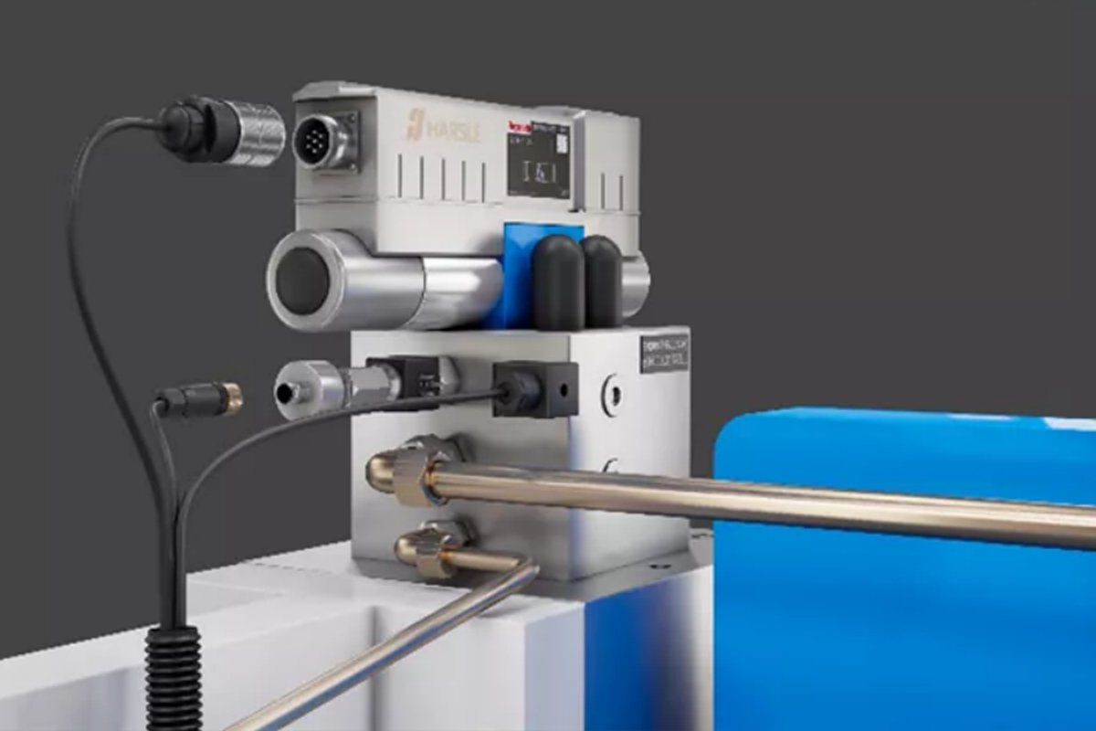
When the current or voltage signal reaches the proportional valve, it first enters the valve’s core component—the Proportional Solenoid. This is the first stage of the “electric-to-force” transformation and the heart of the proportional valve’s technology.
Unlike a standard solenoid, which simply switches fully on or off, a proportional solenoid’s internal architecture—comprising the coil, magnetic guide, and armature—is engineered for one singular purpose: to ensure that the electromagnetic force it generates maintains a highly linear proportional relationship to the input control current.
This means:
- If the input current is 5mA, it produces 10 Newtons of force.
- If the input current is increased to 10mA, it must produce exactly 20 Newtons of force.
This uncompromising linearity is the foundation for all subsequent precision control. The generated force acts directly on a small internal spring, with changes in force precisely altering the spring’s compression. This, in turn, determines the movement of the next key player—the spool.
2.3 The Precision Dance: How Spool Movement Achieves Continuous Control Over Hydraulic Flow, Pressure, and Direction
The spool is a cylindrical slider, polished to a mirror finish and machined to micron-level tolerances, that moves within an equally precise bore inside the valve body. The spool features several complex annular grooves, while the valve body aligns with corresponding ports—the pressure inlet (P), return port (T), and working ports (A/B) leading to the two chambers of the hydraulic cylinder.
The proportional solenoid’s precise force controls the axial displacement of the spool. In effect, the spool acts as an intricately designed fluid controller, enabling continuous adjustment of three key parameters of high-pressure hydraulic oil:
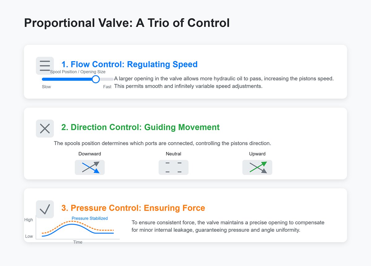
- Flow Control (Determines Speed): The farther the spool moves, the larger the “opening” (technically known as the throttle port) formed between its grooves and the valve body ports. A larger opening allows more hydraulic oil to pass per unit time, increasing the piston’s speed. Conversely, a smaller opening slows it down. Since the opening can be set anywhere between fully closed and fully open, infinitely variable speed control is possible.
- Direction Control (Determines Movement Direction): In its neutral position, the spool sits centered. Moving it to the left might connect port P to port A and port B to port T, driving the cylinder piston downward; moving it to the right might connect port P to port B and port A to port T, driving the piston upward. By controlling the spool’s direction and position, the CNC achieves precise control over the slider’s movement direction.
- Pressure Control (Determines Force): While our focus is on a proportional directional flow valve, adjusting the throttle opening also indirectly influences system pressure. More importantly, during the pressure-holding stage, the proportional valve can maintain a precise opening as instructed by the CNC to offset any minor internal leakage, ensuring consistent bending pressure and angle uniformity.
2.4 The Eye of Correction: How Closed-Loop Feedback Systems Operate (Real-Time Calibration via Optical Encoders/Displacement Sensors)
The process described so far represents an “open-loop” command execution—CNC sends a command, and the proportional valve faithfully carries it out. However, variations such as higher resistance in one pipeline or slight differences in oil temperature can cause deviations between the actual motion of each slider side. Achieving true micron-level synchronization requires the “eye of correction”—a robust closed-loop feedback system.
2.4.1 Signal Flow: From CNC to Valve, Then Back from Sensor to CNC
A complete, tireless closed-loop control signal flow unfolds every millisecond as follows:
- Command: The CNC calculates the target position and sends individual initial current signals to the proportional valves on both sides (e.g., 12.00mA each to Y1 and Y2).
- Execution: Each proportional valve translates the 12.00mA input into a specific valve opening, allowing hydraulic oil to drive the cylinders and move the slider downward.
- Monitoring: High-precision optical encoders mounted on the C-frames at both sides of the machine measure the actual position of each slider side at extremely high frequencies (e.g., Y1 at 50.10mm and Y2 at 50.12mm at a given moment).
- Feedback: The encoders send these real-world position measurements back to the CNC at high speed in the form of digital pulse signals.
- Compare & Correct: The CNC instantly compares the feedback values to the target values, detecting that Y2 is 0.02mm ahead of Y1—indicating a synchronization error. It immediately decides to lower Y2’s valve signal from 12.00mA to 11.95mA (to slow it down) while raising Y1’s signal to 12.05mA (to speed it up), eliminating the 0.02mm difference in the next control cycle.
This “command → execution → monitoring → feedback → correction” loop runs continuously at speeds beyond human reaction capability, suppressing any factor that might disrupt synchronization before it can take effect.
2.4.2 Key Mechanism: How the PID Algorithm Corrects Synchronization Errors in Real Time
In step 5 above, CNC’s “correction” is not a simplistic “slow down if ahead, speed up if behind” approach. Instead, it employs a classic, time-tested, and highly effective mathematical model—the PID control algorithm—the very soul of high-precision dynamic control.
- P (Proportional) – The Impulsive One: This is the core adjustment. The greater the error, the stronger the correction. Picture driving: if you drift 1 meter off your lane, you’ll steer back more sharply than if you were only 1 centimeter off. It reacts quickly and proportionally to visible errors, ensuring the system’s responsiveness.
- I (Integral – The “Persistent Perfectionist”): This component eliminates “steady-state error,” the tiny discrepancies that remain even after P-adjustment has done its job. For example, if one hydraulic cylinder naturally has slightly more friction than the other, the result is a subtle, ongoing lag. The I term accumulates this small, persistent error over time, and once the sum reaches a threshold, it generates an extra, continuous corrective force—as if saying, “You’ve been a bit slow on this side; I’ll keep adding pressure until the error is completely gone.” It’s the solution for those “always just a hair off” perfectionist concerns.
- D (Derivative – The “Forecaster”): This term handles prediction and damping, preventing overcorrection. D doesn’t care about the size of the error—it focuses on how quickly the error is changing. If it detects that the error is being reduced rapidly, it anticipates, “At this rate, we’ll overshoot for sure!” and applies a counteracting force ahead of time, much like easing onto the brake as you approach your destination. This helps prevent overshoot and oscillation, making the adjustment process smoother and more refined.
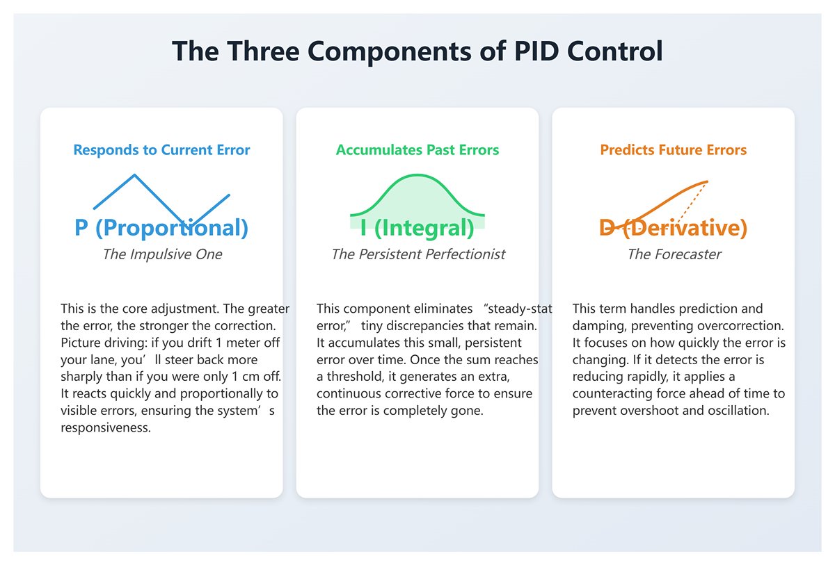
It’s the combined expertise of P, I, and D working in harmony that enables CNC systems to correct synchronization errors in real time with a blend of speed, accuracy, and stability—transforming a cold machine into a precision artist capable of micrometer-level control.
III. Masterclass in Practice: Step-by-Step Guide to Proportional Valve Tuning, Operation, and Parameter Setup
3.1 The Four Phases of a Bending Cycle: The Complete Motion Sequence of Proportional Valves in Action
In a typical bending cycle, the proportional valve performs like a seasoned dancer under the CNC’s direction—at times moving with explosive speed, at others with delicate grace. Understanding its role in each stage is the foundation for precise calibration.
3.1.1 Rapid Downstroke: Maximum Flow for Maximum Efficiency
- CNC Command: Sends the maximum control signal simultaneously to the proportional valves on both Y1 and Y2 sides (e.g., 10V or 20mA).
- Valve Action: The spool is instantly driven by the solenoid to its fully open position, like a dam gate swinging wide to let hydraulic fluid surge into the upper chamber of the cylinders at maximum flow.
- Core Objective: The ram moves toward the workpiece at top speed (in high-performance machines, exceeding 200 mm/s), minimizing idle travel time. This step is critical for reducing cycle time and boosting productivity—every second saved here translates directly into efficiency gains.
3.1.2 Approach Phase: Precise Speed Control and Pressure Build-Up
- CNC Command: Upon reaching the predefined “speed change point” (usually just a few millimeters above the sheet surface), the CNC instantly drops the control signal from maximum to a precise lower value (e.g., from 10V to 2V, or from 20mA to 6.5mA).
- Valve Action: The spool quickly retracts to a much smaller opening, accurately throttling the flow so the ram transitions smoothly from a sprint to the set bending speed (e.g., 10 mm/s). As the punch gently contacts the sheet, the system begins building the pressure required for bending.
- Core Objective: Achieve a controlled, gentle contact with the material to prevent misalignment, tool wear, or safety hazards caused by high-speed impact—this is the first step toward precision bending.
3.1.3 Pressure Hold and Bending: Fine Signal Adjustments to Ensure Angle Accuracy
- CNC Command: Once bending begins, the CNC operates in its most intensive closed-loop mode. Based on real-time position feedback from the linear encoder, it adjusts the proportional valve signal at millisecond intervals, running the PID algorithm to instantly detect and correct even the smallest synchronization errors.
- Valve Action: The spool now moves only within a tiny range, making rapid micro-adjustments to flow at a micrometer scale. It must counteract the constantly shifting resistance of material deformation, ensuring the ram presses down to the target depth with the precision of a sculptor’s chisel, even under immense pressure.
- Core Objective: Achieve and maintain the target bend angle. At the bottom of the stroke, the CNC may hold a constant signal briefly to maintain pressure, allowing internal stresses in the material to release and minimizing springback—further locking in accuracy.
3.1.4 Rapid Return: Controlled Retraction to Optimize Cycle Time
- CNC Command: Upon completing the bend, the CNC sends a maximum reverse signal to the proportional valve.
- Valve Action: The spool quickly moves to its maximum reverse opening, switching the high-pressure line to the lower chamber of the cylinder while allowing the upper chamber fluid to flow freely back to the tank.
- Core Objective: The ram returns to the top dead center at maximum speed, ready for the next cycle. Efficient retraction is just as vital as rapid downstroke—together they form the complete high-efficiency production loop.
3.2 Initial Setup and Parameter Calibration: Starting Your Proportional Valve System from Zero
When installing a new machine, replacing a valve, or after a major system overhaul, a meticulous parameter calibration is essential. This is akin to a marksman zeroing in their rifle—it's the fundamental step that underpins all subsequent accuracy.
3.2.1 Key Parameters Explained: Understanding and Setting Proportional Gain (P), Integral (I), and Derivative (D)
PID parameters are the heart of dynamic system response. Setting them is not a standalone task—it’s an art of finding the perfect dynamic balance.
- P – Proportional Gain: The “quick reactor” and core driver of response speed. The higher the P value, the more aggressively the system reacts to error, and the faster it corrects. Think of it as the sensitivity of a car’s accelerator—high P means a slight press sends the car surging forward. But too high a P can cause the ram to oscillate or overshoot near the target position, never settling.
- Setup Tip: Set I and D to zero. Gradually increase P from a low value, commanding the ram to make a short move. Observe its stop behavior until slight oscillation appears, then reduce P to about 50–60% of that threshold—this provides an excellent starting point.
- I – Integral Time: the system’s “persistent fighter,” the key to eliminating steady-state error. When the ram stops just a hair’s breadth away from the target position due to gravity or friction (a steady-state error), the integral component keeps accumulating that tiny offset and gradually builds a corrective force strong enough to remove it entirely. A smaller I value (or higher integral gain) accelerates error elimination, but if set too low, it can cause the system to oscillate.
- Tuning Tip: Once you’ve established the optimal P value, gradually decrease the I value (or increase the integral gain) until the steady-state error disappears quickly and smoothly. The key observation is whether the ram stops precisely at the target point—without undershoot or overshoot.
- D – Derivative Time: the system’s “prophet” and “damping force.” The D term anticipates how the error is changing. When it detects that the error is rapidly diminishing, it applies a counteracting force in advance—like gently braking before a stop sign—to prevent the P term from overreacting and causing overshoot. Proper D tuning significantly increases stability and makes the motion smooth and refined.
- Tuning Tip: After setting P and I, if overshoot still occurs, begin carefully increasing the D value from a small starting point until the overshoot is adequately suppressed and the motion becomes steady and “silky.” But beware—too much D makes the system sluggish, as if driven by an overly cautious driver.
3.2.2 Zero and Span Calibration: Ensuring Perfect Alignment Between Signal and Motion
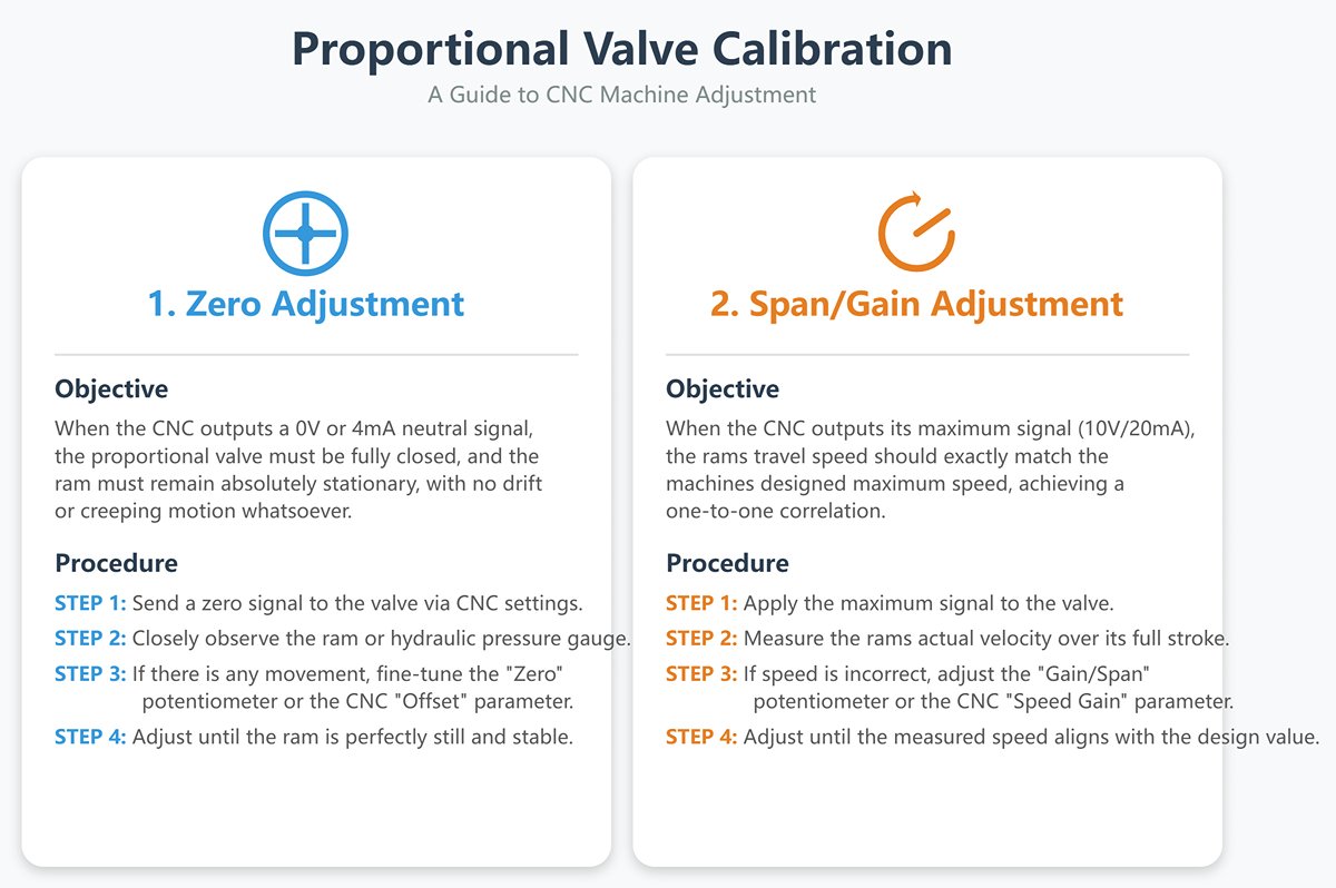
- Zero Adjustment:
- Objective: Ensure that when the CNC outputs a 0V or 4mA “neutral” signal, the proportional valve is fully closed and the ram remains absolutely stationary—no drift or creeping motion whatsoever.
- Procedure: In the CNC settings or manual mode, send a zero signal to the valve. Observe the ram or hydraulic pressure gauge closely. If there’s any slight movement or pressure buildup, fine-tune the “Zero” potentiometer on the valve amplifier or adjust the “Offset” in the CNC parameters (clockwise or counterclockwise) until the ram becomes perfectly still and stable.
- Span/Gain Adjustment:
- Objective: When the CNC outputs its maximum signal (10V/20mA), the ram’s travel speed should exactly match the machine’s designed maximum—achieving a one-to-one correlation between signal and physical limit.
- Procedure: Apply the maximum signal and let the ram travel its full stroke downward at full speed. Use a stopwatch and the position display to measure the actual velocity. If it’s slower or faster than specified, adjust the “Gain/Span” potentiometer on the valve amplifier or the “Speed Gain” parameter in the CNC until the measured speed precisely aligns with the theoretical design value.
3.2.3 Deadband Compensation: Overcoming Valve Spool Inertia for Enhanced Micro-Motion Response
- What Is Deadband? Due to static friction between the spool and valve body, along with hydraulic viscosity, a small range of input change (e.g., 0–0.3V) won’t cause the spool to move. This is known as deadband, akin to the “play” in a car’s steering wheel—a mechanical imperfection inherent to all systems.
- Why Compensate for It? Deadband prevents the system from responding to minute motion commands (e.g., a 0.01mm correction), severely compromising fine positioning and synchronization sensitivity.
- Tuning Tip: In the CNC’s deadband compensation parameter, start from zero and gradually increase the compensation value while issuing a tiny incremental command (e.g., 0.01mm). Keep increasing until the system consistently and smoothly responds to that micro motion. Note: Excessive compensation can cause jumpy micro-movements, so aim for the threshold that “just wakes up” the valve spool.
3.3 Synchronization Accuracy Tuning: The Three-Step Calibration for Perfect Dual-Cylinder Parallelism
This is the final—and technically most sophisticated—stage of commissioning, aiming to make the two independent hydraulic cylinders, Y1 and Y2, operate in flawless harmony.
- Step 1: Verify Mechanical and Hydraulic Integrity — The Foundation Determines the Structure Before touching any software parameter, you must ensure the hardware baseline is absolutely reliable:
- Confirm the ram guideways are well lubricated. Manually rotate the leadscrew (if applicable) or inspect the sliding surfaces to ensure there’s no abnormal resistance.
- Verify that both cylinder seals are intact with no internal leakage. Pro tip: Suspend the ram mid-air, maintain hydraulic pressure, and shut off the pump. Watch both pressure gauges—if one side’s pressure drops significantly faster, that cylinder is leaking internally. Repair it before proceeding—no amount of software tuning can compensate for faulty hardware.
- Ensure both linear scales are securely mounted and that the read heads are clean and free of oil or debris.
- Step 2: Single-Axis PID Optimization — Train Each “Athlete” Individually Enter the CNC’s advanced tuning mode and disable the servo control of Y2, allowing only Y1 to operate. Mount precision dial indicators or magnetic stands at both ends of the ram. Optimize Y1’s PID parameters for fastest, most stable response with zero overshoot. Then disable Y1 and repeat the identical optimization for Y2. The goal is to make sure each “athlete” performs at peak individual capability before team coordination.
- Step 3: Fine-Tune Synchronization Parameters — Perfecting Team Coordination Re-enable dual-axis synchronization and zero both dial indicators. Command the ram to move slowly (e.g., 10 mm/s) through a complete downward and return stroke, keeping a close eye on the difference between the two readings.
- If a consistent, linear deviation exists (e.g., Y1 remains 0.1mm ahead of Y2 throughout the stroke), adjust the CNC’s “Synchronization Gain” or “Y1/Y2 Proportional Gain”—slightly lower Y1’s gain or raise Y2’s until both align.
- If the error is larger at the start/stop points but minimal at constant speed, fine-tune the “Derivative (D)” or “Feedforward” settings to enhance dynamic response symmetry.
- Repeat slow-stroke tests and parameter tweaks until the dial indicator difference remains within the factory precision specification throughout the entire motion (typically ±0.01–0.02 mm for high-precision press brakes). Only then can the machine be considered fully commissioned—fast, stable, and perfectly synchronized.
IV. Strategic Decision: The Ultimate Showdown — Proportional Valve vs. Servo Valve vs. Torsion Bar
4.1 Technical Overview: Core Operating Principles of Three Mainstream Synchronization Methods
To make the right choice, we must strip away the surface and look directly at the technological core.
- Torsion Bar Synchronization: Pure Mechanical “Forced Binding”
- Core Principle: This is a purely mechanical, open-loop system. A high-rigidity steel torsion bar runs through the upper section of the press brake, physically linking the piston rods of the hydraulic cylinders on both sides. It works much like carrying water with a sturdy shoulder pole: the rigidity of the bar forces both ends to move in unison. The control system does not monitor the actual position of the ram—it simply drives the cylinders—leaving the entire synchronization task to the mechanical torsion bar. This is a passive, relatively crude form of enforced synchronization.
- Electro-Hydraulic Proportional Valve Synchronization: Intelligent “Closed-Loop Fine-Tuning”
- Core Principle: This is a sophisticated electro-hydraulic closed-loop feedback system. It completely eliminates the bulky torsion bar, giving each cylinder (Y1 and Y2) full independent movement. The CNC control system acts as the “brain,” using high-precision linear encoders—the “eyes” mounted on each side—to continuously read the ram’s exact position. If any deviation is detected, the brain instantly sends precisely calculated, independent analog signals to the “nervous center” of each cylinder—the proportional valve. The valves then adjust hydraulic flow (and thus speed) proportionally and continuously according to signal strength, creating an uninterrupted loop of command, execution, feedback, and correction—actively eliminating errors as soon as they arise.
- Electro-Hydraulic Servo Valve Synchronization: Ultimate “Instant Response”
- Core Principle: This represents the pinnacle of hydraulic control technology—an advanced evolution of the proportional valve approach. The system architecture is similar, but the core control component is upgraded from a proportional valve to a servo valve with a dramatically faster response. If the proportional valve is a high-performance luxury sedan, the servo valve is an F1 race car. It offers virtually zero deadband, millisecond-level response times, and unmatched precision. This allows it to detect and correct ultra-fine, high-speed errors beyond the reach of proportional valves—delivering the highest level of hydraulic control possible.
4.2 Multi-Dimensional Comparison Matrix: Comprehensive Evaluation of Accuracy, Speed, Cost, Maintenance, and Applicability
A single chart can often speak louder than a thousand words. The matrix below offers a clear, visual decision-making reference.
| Dimension | Torsion Bar Synchronization | Proportional Valve Synchronization | Servo Valve Synchronization |
|---|---|---|---|
| Control Principle | Mechanical open-loop | Electro-hydraulic closed-loop | High-performance electro-hydraulic closed-loop |
| Synchronization Accuracy | ★☆☆☆☆ (Low, approx. ±0.1mm) | ★★★★☆ (Good, approx. ±0.01mm ~ ±0.02mm) | ★★★★★ (Extreme, within ±0.005mm) |
| Response Speed | ★☆☆☆☆ (Slowest) | ★★★★☆ (Fast) | ★★★★★ (Fastest, extremely high frequency response) |
| Load Compensation Capability | ☆☆☆☆☆ (Poor, severe off-center loading can damage the torsion bar) | ★★★★☆ (Good, closed-loop system dynamically compensates) | ★★★★★ (Excellent, independent control handles it with ease) |
| Initial Investment Cost | ★★★★★ (Lowest) | ★★★☆☆ (Moderate) | ★☆☆☆☆ (Highest, valves and systems are expensive) |
| Maintenance Complexity | ★★★★★ (Simplest, purely mechanical structure) | ★★★☆☆ (Moderate, requires hydraulic and electrical expertise) | ★☆☆☆☆ (Highest, demands exceptional oil cleanliness and skilled technicians) |
| Automation Integration | ★☆☆☆☆ (Poor, insufficient repeat positioning accuracy) | ★★★★☆ (Good, meets most automation needs) | ★★★★★ (Excellent, perfect repeatability is the foundation of unmanned operation) |
| Suitable Applications | Low-precision, high-volume, simple parts | Most versatile, covers the majority of precision sheet metal work | Aerospace, medical devices, parts with ultra-high precision requirements |
4.3 Selection Guide: Choosing the Optimal Technology Path Based on Your Production Needs
Answering these three soul-searching questions will help you pinpoint the technology path that fits your needs:
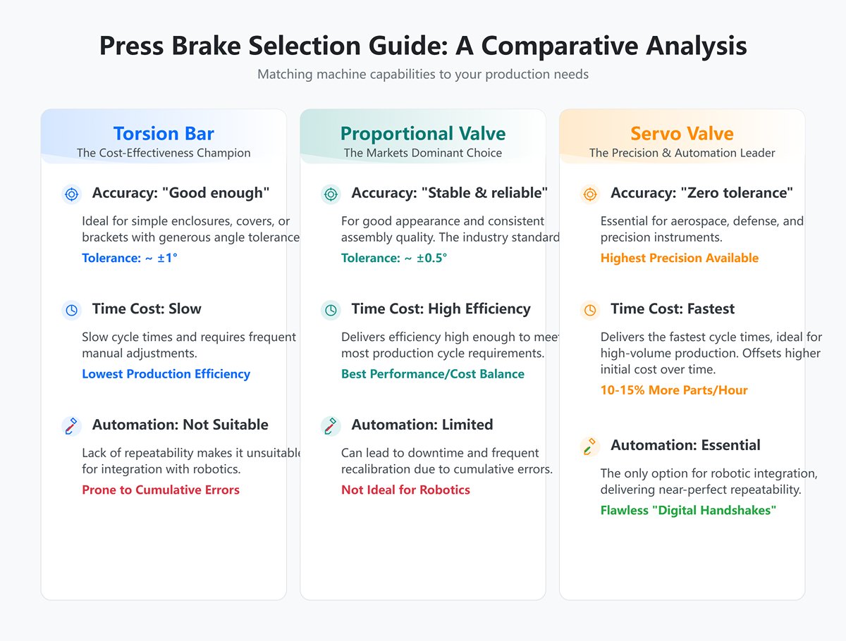
- Question 1: Where is your “accuracy lifeline”?
- “Good enough”: If your products are simple enclosures, covers, or brackets with generous angle tolerances (around ±1°), the lowest-cost torsion bar press brake will do the job—it’s the undisputed champion of cost-effectiveness.
- “Stable and reliable”: If your products need good appearance and consistent assembly quality, keeping angle tolerances within ±0.5°, you’re in the territory of most precision sheet metal shops. The proportional valve synchronization press brake offers the best balance of performance and cost—making it the dominant choice in the market and the wisest general-purpose solution.
- “Zero tolerance”: For aerospace, defense, precision instruments, or parts requiring flawless robotic welding, even the slightest angle deviation can mean scrapping expensive components. In such cases, the servo valve synchronization press brake is your only—and essential—option.
- Question 2: How much does “time” cost you?
- Torsion bar machines are slow and require frequent manual adjustments, resulting in the lowest production efficiency.
- Proportional valve machines deliver high enough efficiency to meet most production cycle requirements.
- Servo valve machines deliver the fastest cycle times. In high-volume, automation-driven production lines aiming for the shortest possible cycle time, producing 10–15% more parts per hour can, over time, completely offset their higher initial cost.
- Question 3: Are you embracing—or planning to embrace—automation?
- If you plan to integrate a bending robot into an automated work cell, repeat positioning accuracy becomes the decisive factor. Only servo valve synchronization press brakes can deliver near-perfect repeatability, enabling flawless “digital handshakes” with the robot during every pick, position, bend, and stack cycle. Using other machine types in automation often leads to downtime and frequent recalibration due to cumulative errors—negating the intended gains.
4.4 Valve Type Breakdown: Distinct Roles of Proportional Directional Valves, Flow Control Valves, and Pressure Valves in Press Brakes
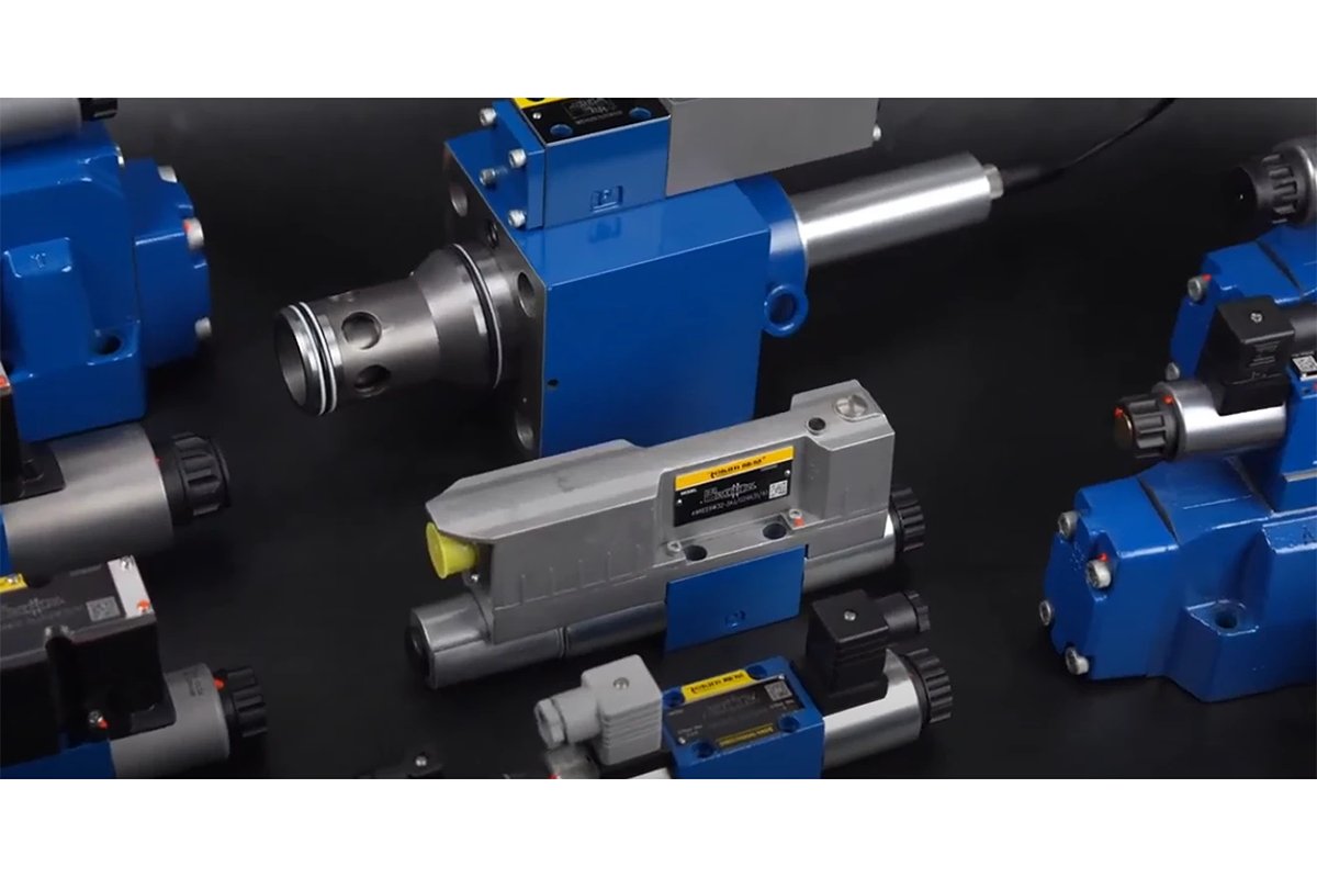
In everyday conversation, we often loosely refer to the main control valve on a press brake as the “proportional valve.” However, from a precise hydraulic engineering perspective, this is actually a coordinated team of different types of proportional valves, each with its own distinct role, working together in harmony.
- Proportional Directional & Flow Control Valve
- Role: The powerhouse of synchronization control. This is the core valve we’ve been examining in depth throughout this chapter, mounted to the hydraulic cylinders on both the Y1 and Y2 sides. It is a highly integrated composite valve with remarkable precision: by controlling the direction of the spool’s movement, it determines whether the cylinder extends or retracts (i.e., the ram moves up or down). By controlling the distance the spool moves (its opening), it finely adjusts the flow rate through the valve (i.e., the ram’s movement speed). This is the heart of closed-loop speed and position control.
- Proportional Pressure / Relief Valve
- Role: The precise tuner of system tonnage. Usually installed in the main hydraulic line at the pump station, this valve acts as the machine’s “guardian of force.” The operator can set the exact maximum tonnage needed for a bending cycle directly via the CNC (for example, 100 tons). When system pressure reaches this preset value, the proportional relief valve automatically opens a precisely regulated bypass, returning excess oil to the tank. This keeps the working pressure exactly at the required tonnage, protecting costly tooling and workpieces from overload damage and enabling fine-tuned pressure control.
- Proportional Flow Control Valve
- Role: A dedicated speed controller. While the primary synchronization valve already handles flow control perfectly, in certain highly complex, custom hydraulic systems, there may be separate proportional flow valves dedicated to controlling the speed of specific auxiliary movements—such as the hydraulic drive of a special axis on the backgauge. In modern standard press brakes, this functionality is almost always integrated into the main synchronization valve.
In summary, the precise operation of a modern electro-hydraulic synchronized press brake relies mainly on the proportional directional & flow control valve for micron-level synchronization and smooth speed control, and on the proportional pressure valve for Newton-level tonnage regulation. Under the unified command of the CNC, they perform a symphony of force and precision, orchestrated entirely by electrical signals.
V. Troubleshooting & Maintenance Master Guide: Swift Solutions to 90% of Proportional Valve Issues
5.1 Symptom Diagnosis: A Problem-Based Troubleshooting Roadmap
When problems arise, the most efficient approach is not to start dismantling parts blindly, but to follow the golden rule: work from outside in, from simple to complex, and check software before hardware. This method leads you step by step, like peeling an onion, until you reach the root cause.
5.1.1 Symptom One: Poor Cylinder Synchronization—Uneven Bend Angles
This is the most classic and common fault in electro-hydraulic synchronized press brakes. Follow this surgical-style, step-by-step diagnostic sequence:
- Layer One: Check the Mechanical Baseline: Before touching any electrical or hydraulic components, first rule out basic mechanical issues. Use a level to check the machine’s alignment. Ensure the upper and lower dies are perfectly aligned and secure, with reliable clamping. Inspect the guide surfaces on both sides of the ram for debris or poor lubrication—these can cause inconsistent physical resistance.
- Layer Two: Clean the “Eyes” (Optical Encoder): Using a lint-free cloth and industrial alcohol, carefully clean the glass scale and read head of the encoder on the faulty side. In a sheet metal workshop filled with oil mist and dust, contamination of the encoder is the number one cause of reading errors and synchronization deviations. Even a tiny smudge can blind the system.
- Layer Three: Check the “Nerve Connections” (Signal Path): Inspect the encoder’s signal cable connectors for looseness caused by vibration or pin oxidation. Also check that the proportional valve solenoid’s aviation connector is securely fastened. A loose connection, like an intermittent instruction, will inevitably cause erratic movement.
- Layer Four: Perform the “Cross-Diagnosis” Method (Amplifier Swap): A go-to technique for professional engineers to quickly narrow down faults. With the power fully off and safety assured, carefully swap the proportional valve amplifiers (or CNC drive cards) between the Y1 and Y2 axes. Power up and test. If the fault shifts from the original side (e.g., Y1) to the other (Y2), you’ve pinpointed the amplifier as the culprit. If the fault stays on the original side, the amplifier is fine, and the problem lies in the valve itself or the hydraulic cylinder.
- Layer Five: Diagnose the “Valve Heart” (Valve Core & Cylinder):
- Zero Position Offset Check: In manual mode, hold the ram suspended. If one side tends to drift downward, the proportional valve’s mechanical or electrical zero point on that side is off and needs recalibration as per Chapter 3.
- Ultimate Cylinder Internal Leakage Test: This is the definitive check for cylinder seal integrity. Position the ram mid-stroke, then switch off the hydraulic pump. Watch the CNC display for Y1 and Y2 coordinates. If one side’s reading steadily and visibly decreases (e.g., -0.01, -0.02, -0.03…), it’s clear proof that the cylinder’s piston seal is worn, allowing high-pressure oil to leak across the piston. This is a purely mechanical fault—no software tuning will help—and the seals must be replaced.

5.1.2 Symptom Two: Ram Responds Slowly, Jerks, or Moves Unsteadily
- Check the “Blood Quality” (Hydraulic Fluid): Start with the hydraulic oil. Is the reservoir oil level too low, causing the pump to draw in air? Has the oil degraded or emulsified due to contamination or prolonged use? Measure the oil temperature—too high (>60°C) or too low (<15°C) will significantly alter its viscosity, severely affecting the system’s dynamic response.
- Perform an “Air Purge”: Air trapped inside the hydraulic system is a frequent cause of jerky or “crawling” motion. Try moving the slide continuously back and forth across its full stroke at a low speed (5–10 mm/s) for 5–10 cycles. This action helps dislodge tiny air bubbles within the pipes and cylinders, allowing them to return to the tank and escape.
- Review the “Control Brain” (PID Parameters): Improper PID settings are a direct trigger for oscillations—particularly an overly high P (Proportional Gain) or a too-short I (Integral Time). Following the tuning techniques discussed in Chapter 3, try slightly reducing the P-value or increasing the I-value, then observe whether the oscillation improves.
- Eliminate “Signal Noise” (Electrical Interference): Open the electrical cabinet and inspect the control signal cables of the proportional valve—these are typically shielded twisted pairs. Ensure they aren’t tied together tightly with the high-power motor cables, which can generate strong electromagnetic interference that corrupts analog signals and causes irregular valve movement. The signal cables must have proper shielding and grounding, and should be routed separately from power lines.
- Identify “Spool Stiction”: If the jitter occurs consistently at a particular position or speed in the stroke, it strongly suggests that the valve spool is sticking slightly due to tiny solid particles suspended in the hydraulic fluid.
5.1.3 Symptom 3: Pressure Fluctuations or Failure to Reach the Set Value
- Check the “Command Source” (Pressure Setting): Begin with the simplest step—verify that the maximum system pressure value (tonnage) set in the CNC parameters hasn’t been unintentionally changed.
- Focus on the “Main Pressure Line” (Proportional Pressure Valve): Most likely, the issue lies in the proportional pressure valve (or proportional relief valve) on the main line of the hydraulic station. Check that its electrical connections are secure. More commonly, contamination in the hydraulic oil causes the valve to stick partially or fully open, much like a faucet that won’t shut off completely, preventing the system from building pressure.
- Inspect the “Pressure Gauge” (Pressure Sensor): If the pressure reading on the CNC display fluctuates rapidly—similar to an electrocardiogram—rather than remaining steady, it could indicate that the sensor is failing or that its signal cable has a poor connection.
- Examine the “Power Heart” (Hydraulic Pump): If pressure cannot be built up at all, accompanied by loud and unpleasant noise, stop the machine immediately. Then check whether the pump is rotating in the correct direction and whether it shows signs of severe wear or damage.
5.1.4 Symptom 4: CNC System Reports Alarm Codes Related to the Proportional Valve
This is the system’s most direct form of communication. Never develop the bad habit of simply clearing alarms without investigation. Each code is a critical clue to solving the problem.
- Decode the “Cipher” (Consult the Manual): Immediately refer to the machine’s electrical or operation manual to find the exact meaning of the alarm code and the recommended troubleshooting steps.
- “Servo/Driver Fault”: This type of alarm usually points to the amplifier for the proportional valve. Check the indicator lights on the amplifier (typically power, enable, and fault) and verify that the 24VDC power supply is normal.
- “Feedback Loss/Encoder Fault”: This alarm indicates that the problem is not with the proportional valve itself, but with its “eyes”—the linear encoder. Inspect the encoder cable and its read head carefully.
- “Coil Open/Short Circuit”: This represents a final verdict on the valve’s solenoid. Disconnect the valve plug and measure the resistance between the two terminals of the coil with a multimeter. A healthy coil should have a fixed resistance value (usually between 10–50Ω). An infinite reading (OL) indicates an open circuit, while a reading of 0Ω or near 0Ω indicates a short circuit. Either condition means the solenoid has suffered physical damage and must be replaced.
5.2 The Core of Maintenance: Golden Rules for Extending Proportional Valve Life
Rather than scrambling to fix failures after they occur, invest in excellent maintenance to prevent them. Proportional valves are delicate precision components—proper care can easily extend their designed lifespan severalfold.
5.2.1 The Lifeline of Hydraulic Oil: ISO Cleanliness Grades and Scheduled Replacement/Filtration
Engrave this in your mind: this is the single most important maintenance principle—no exceptions! 90% of premature proportional valve failures are caused by contaminated hydraulic oil.
- Understand ISO 4406 Cleanliness Ratings: High-precision proportional and servo valves demand extremely strict oil cleanliness—typically ISO 16/14/11. These numbers aren’t abstract—they mean that for every 100 milliliters of oil, particle counts must not exceed: 320–640 larger than 4 μm, 80–160 larger than 6 μm, and fewer than 20 larger than 14 μm. For comparison, a single human hair is 50–70 μm thick. The lethal particles that can instantly destroy your expensive valves are completely invisible to the naked eye.
- The Three Golden Rules of Hydraulic Maintenance:
- Pure Lineage: Never use cheap, unverified, or incorrectly graded hydraulic oil. Always use the high-quality, anti-wear oil brand and grade recommended by the equipment manufacturer.
- Regular “Blood Replacement”: Replace all hydraulic oil and filters in strict accordance with the maintenance manual—typically every 2,000–4,000 operating hours. In high-precision or high-load environments, it’s strongly recommended to use an offline filtration system regularly to circulate and purify the tank oil, keeping the cleanliness at its optimal level.
- New Oil ≠ Clean Oil: A critical insight worth remembering—oil straight from a sealed barrel typically only meets about ISO 20/18/15 cleanliness, far below valve requirements. Therefore, when refilling, always pass new oil through a high-precision filter. This single practice distinguishes professional maintenance from amateur handling.
5.2.2 Electrical Inspection: Signal Shielding, Connector Tightening, and Coil Resistance Testing
- The Electromagnetic “Shield”: Ensure that the shielding layer of the proportional valve’s control cable is properly grounded at the CNC end. This effectively blocks electromagnetic interference from devices like inverters or servo motors, preserving the integrity of control signals.
- Eliminate “Loose Connections”: During monthly maintenance, manually verify that each circular connector on the valve solenoids is fully tightened. Continuous machine vibration can loosen them over time, leading to intermittent electrical contact.
- Create a “Health Record”: As part of the annual maintenance, systematically measure and record the normal coil resistance of every proportional valve at room temperature. This historical data will become your fastest and most reliable reference when diagnosing future electrical faults.
5.2.3 Preventive Maintenance Checklist: A Practical Daily, Monthly, and Annual Care Plan
Print out the following checklist and post it next to your equipment—it will serve as a steadfast guardian of your machine’s health.
- Daily:
- Before starting up, verify that the oil tank level gauge and oil thermometer are within the normal range (oil level > 2/3, oil temperature < 60°C).
- While the equipment is running, listen for any unusual noises from the hydraulic pump.
- Visually inspect all proportional valves and pipeline joints for any noticeable oil leakage.
- Monthly:
- Check the clogging indicators or differential pressure sensors on the hydraulic system’s pressure and return filters.
- Use clean compressed air to blow away dust from the heatsinks of the proportional valve amplifiers and CNC control cabinet, ensuring proper heat dissipation.
- Inspect and tighten all electrical connections, including relays, contactors, and wiring terminals.
- Annually:
- Take a sample of the hydraulic oil for laboratory analysis, and based on the report, decide whether to carry out fine filtration or a complete oil replacement.
- Regardless of oil condition, replace all hydraulic filters (pressure, return, and suction).
- Have a professionally trained engineer use specialized instruments to re-check and calibrate all proportional valves’ null position, gain, and dead-zone compensation parameters, restoring the entire system to peak factory performance.
VI. Conclusion
In summary, the proportional valve is the soul of a press brake's accuracy, expertly converting CNC signals into controlled hydraulic power. From its core principles and PID tuning to strategic selection and troubleshooting, we've shown that to master the valve is to master precision bending.
At ADH, we live and breathe this technology. To leverage this expertise and elevate your bending operations, contact us today or explore our detailed Brochures to see how our solutions can fit your production needs. Let's build precision into your process.


