The question, "How fast is a press brake?," often focuses on spec sheet numbers, but this is misleading. True productivity isn't about ram velocity; it's about the 'production tempo'—the total cycle time to create one part. This guide looks beyond raw speed to deconstruct the hidden factors that truly govern your output, offering a clear path to maximizing your real-world efficiency.
I. Breaking the Myth: From Chasing “Speed” to Mastering the “Rhythm” — Redefining Your Productivity Mindset
1.1 Core Insight: The right question isn’t “How fast?” — it’s “How long does it take to produce one part?”
Even if a press brake’s ram moves at lightning speed, that’s just one note in the entire production symphony. What truly dictates profitability is playing the whole piece — the complete single-piece cycle time.
Cycle time is like an iceberg: we usually see only the small portion above the surface — the machine’s active processing time. But the real mass lies hidden beneath, in the form of three major time components:
- Processing Time: The machine’s “stage time,” comprising three main speed phases — rapid approach, bending process, and rapid return. For complex parts with multiple bends, you must also factor in the crucial backgauge repositioning time between steps.
- Handling Time: The “human time,” covering the operator’s actions — picking up sheet stock, accurately positioning it against the backgauge, removing and stacking the finished part. Operator skill, ergonomic layout, and even lighting conditions directly affect this stage’s efficiency.
- Setup Time: The often-overlooked productivity killer. This includes changing tooling, loading or programming jobs, calibrating the backgauge and stroke limits, and test bends with adjustments. In high-mix, low-volume production, setup can consume over 70% of total labor hours, becoming the biggest bottleneck.
That’s why chasing maximum approach or return speeds without optimizing backgauge agility, tool change convenience, or programming efficiency is like fitting tractor tires on an F1 car — you’ve got the roar of the engine, but you won’t win on the track.
1.2 Quick Reference: Typical Press Brake Speed Ranges (Learn in 30 Seconds)
While speed shouldn’t be your sole metric, knowing the basic parameters is still a good starting point. The table below outlines typical speed ranges for today’s mainstream CNC press brakes. Note that actual figures vary by tonnage, drive technology, and safety systems.
| Speed Type | Hydraulic Press Brake | Electric Servo Press Brake | What does this mean? |
|---|---|---|---|
| Rapid Approach Speed | 100–220 mm/s | 150–250 mm/s | No-load efficiency: the speed at which the ram moves from its highest point toward the workpiece. Servo-driven models respond faster here, offering a clear advantage. |
| Bending Speed | 5–15 mm/s | 1–20 mm/s | Precision control: the actual speed during tool contact and bending. Slower speeds ensure accurate angles and controlled material springback. |
| Rapid Return Speed | 100–220 mm/s | 150–250 mm/s | Cycle reset: the ram’s speed returning to the start position after bending. Servo models benefit from instant start/stop with no hydraulic lag. |
Key takeaway: Electric servo press brakes generally lead in speed, especially in response time and no-load travel. But that doesn’t mean they’re the most efficient choice in every scenario. The real answer lies in the value framework we’ll explore next.
1.3 What This Guide Delivers
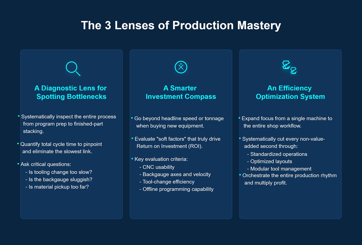
By the end of this guide, you’ll gain far more than a few dry numbers. You’ll make the leap from “operator” to “conductor” of your production rhythm, gaining three core benefits:
- A diagnostic lens for spotting production bottlenecks: You’ll learn to systematically inspect the entire process from program prep to finished-part stacking. Is tooling change too slow? Is the backgauge sluggish between steps? Is material pickup too far from the machine? By quantifying total cycle time, you can pinpoint and eliminate the slowest link.
- A smarter investment compass: When buying new equipment, your criteria will go beyond headline speed or tonnage. You’ll evaluate CNC usability, backgauge axes and velocity, tool-change efficiency, and whether offline programming can enable zero-downtime changeovers. These “soft factors” are what truly drive ROI.
- An efficiency optimization system for multiplying profit: Your focus will expand from a single machine to the entire shop workflow. Through standardized operations, optimized layouts, and modular tool management, you’ll systematically cut every non-value-added second. You’ll no longer just run a machine — you’ll orchestrate the entire production rhythm as a leader in operational excellence.
Now, let’s dive into the details behind press brake speed and open the door to peak efficiency.
II. Deep Analysis: Breaking Down the Three Key Speed Phases of a Press Brake
We’ve established that single-piece cycle time is the gold standard for measuring efficiency. Now, let’s zoom in on the heart of that iceberg — the machine’s processing time. A bending cycle may look simple, but it’s actually a precise dance of three tightly linked phases, each with its own purpose. Mastering and optimizing these phases is your first step toward becoming an efficiency expert.
2.1 Phase One: Rapid Approach (Y-axis Down) — The Sprint to the Workpiece
This is the opening whistle of the efficiency race. The ram (upper die) drops from its highest point toward the stationary sheet at maximum speed. The aim here is simple: minimize no-load travel time without compromising safety.
But the winner of this sprint isn’t the machine with the highest theoretical speed — it’s the smartest one. The true limits aren’t defined by the maximum output of a hydraulic pump or servo motor, but by two invisible reins: safety and control.
- Core Constraint: Speed Change Point and Safety Light Curtain
Picture a race car hurtling toward the finish line—it must brake at precisely the right moment. In a press brake, this "braking point" is known as the Speed Change Point. Here, the ram must instantly shift from a rapid approach speed—often 200 mm/s or more—down to a safe, controlled bending speed of around 10 mm/s. The closer this change point is set to the workpiece, the shorter the no-load travel time. What determines this point is the safety light curtain system. According to international safety standards such as ISO 13855, the safety distance ($S$) depends on the system's total stop reaction time ($T$). In short: Faster safety PLCs, more responsive light curtains, and quicker hydraulic valves/servo drives = shorter reaction time (T) = smaller safety distance (S). This means a press brake with a top-tier safety system can legally delay deceleration until it’s much nearer to the sheet, effectively "gaining" tens to hundreds of milliseconds in every cycle. This is the first secret behind the speed advantage of high-end machines: they don’t necessarily run faster—they brake later. - The Art of Optimization: From Aggression to Intelligence
Chasing maximum approach speed blindly often leads to severe mechanical shock and hydraulic jolts at the speed change point—producing a sharp "tool slam" noise and even leaving initial marks on the workpiece that compromise first-piece accuracy. True optimization comes from smooth transitions. Modern CNC systems employ "soft switch" functions to gently decelerate before reaching the change point, ensuring a soft contact. This protects both tooling and machine while stabilizing the initial bending phase, laying the groundwork for perfect one-shot forming.
Expert Insight: Stop asking suppliers, “How fast is the rapid descent?” Instead, ask, “What is your safety system’s reaction time, and can the speed change point be controlled precisely and smoothly?” That’s the real key to approach-phase efficiency.
2.2 Phase Two: Bending Operation (Y-axis Work Stroke) – Where Precision Meets Power
Once the upper tool meets the sheet, the speed race comes to an abrupt halt, and a finely tuned ballet begins. This is the critical stage that defines the final product’s quality—its angle, radius, and surface finish. Here, the priority shifts from “fast” to “accurate.”
At this point, speed becomes a delicate variable, balanced against accuracy, material behavior, and tooling characteristics.
- The Price of Speed: Why Slower Can Be Faster
Bending too quickly—say above 15–20 mm/s—can trigger a cascade of problems:- Unstable Angles: At high deformation speeds, metal rebound becomes erratic and hard to predict, resulting in poor angle consistency.
- Surface Damage: Especially when using small V-dies or working with stainless steel or aluminum, excessive speed increases friction between material and tooling, causing irreparable galling or scratches.
- Tool Overload: Sudden impact forces can chip or fracture delicate die edges.
That’s why seasoned engineers deliberately set bending speeds to a modest range—typically 5–15 mm/s—to ensure getting the correct angle in one go. Any rework or scrap caused by excessive speed will quickly erase any time savings gained in the approach phase.
- The Overlooked Time Factors: Dwell and Decompression
Reaching the target depth doesn’t mean the ram immediately retracts. Two critical “hidden” time segments occur here:- Dwell Time: A brief pause at the bottom of the bend, typically 0.05–0.5 seconds. This “calm period” allows internal stresses in the material to settle and redistribute, greatly reducing springback and enhancing angle stability. For high-strength steels or demanding bends, a well-set dwell time is indispensable for accuracy.
- Decompression Time: A controlled release of maximum pressure. This is especially crucial for hydraulic press brakes—if decompression is too rapid, the sudden return flow of hydraulic fluid can cause “hydraulic shock,” leading to angle rebound.
Expert Insight: Check your program—does your bending speed taper in stages? (For example, slightly faster in the early stroke, then crawling at micro-speed for the last 1–2 mm to secure accuracy.) Have you set optimal dwell times for different materials and thicknesses? Neglecting these two parameters is like planting a ticking time bomb in both efficiency and quality.
2.3 Phase Three: Rapid Return (Y-axis Fast Up) – Resetting for the Next Burst
After bending, the ram races back to the starting point at maximum speed. On the surface, this is simply the reverse of the approach phase—but from a production rhythm standpoint, it’s much more. The return stroke is an efficiency goldmine and the perfect moment for parallel actions.
A “smart” press brake never wastes the 0.5–1.5 seconds of return time. As the ram rises, several preparations for the next bend happen simultaneously:
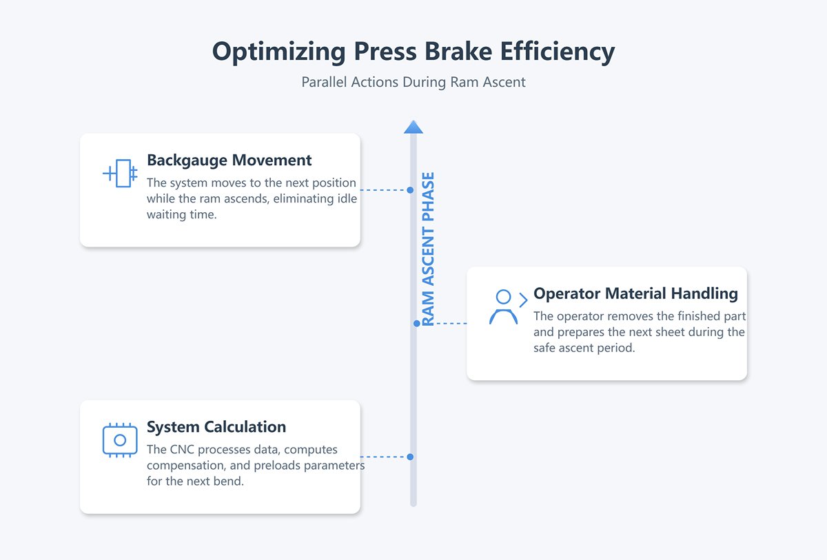
- Backgauge Movement: The most critical parallel action. For complex parts requiring multiple bends, the backgauge system begins moving to the next position while the ram is still ascending. By the time the ram reaches the top, the backgauge is already in place—virtually eliminating what would otherwise be idle waiting time.
- Operator Material Handling: During the safe period of ram ascent, skilled operators can remove the finished workpiece and prepare the next sheet. This is where smooth human–machine coordination shines.
- System Calculation and Data Processing: The CNC uses return time to process angle measurement data (if equipped with angle sensors), compute compensation values, and preload all parameters for the next bend.
Let’s use a simple calculation to quantify the impact of these three phases:
Scenario Assumptions:
- Approach/return distance: 120 mm each; speed: 180 mm/s
- Bend depth: 8 mm; speed: 10 mm/s
- Dwell time: 0.2 s; decompression time: 0.15 s
Pure Machine Cycle Time for a Single Bend (Y-axis Cycle Time):
That 2.49 seconds represents the theoretical limit for a single “bowing” motion of the machine. If a workpiece requires four bends and the backgauge can reposition during the return stroke, the total processing time per part is roughly ten seconds. Add the “auxiliary time” we discussed in Chapter 1—loading and unloading—and you arrive at a very realistic estimate of the actual cycle time per piece in production.
At this point, you’ve mastered the analytical framework for understanding the core speed behavior of a press brake. You’re no longer just observing surface-level numbers—you’ve become a diagnostic expert capable of uncovering efficiency potential hidden within the approach, bending, and return phases. Next, we’ll reveal the unsung heroes inside the machine’s “heart” and “brain” that truly govern this performance.
III. Unveiling the Hidden Forces: The Five Real Factors Behind Your "Actual Speed"
You’ve already grasped the micro-rythm of ram motion, but that’s just the tip of the iceberg. What determines real shop-floor productivity lies within and around the machine itself—the macro systems that influence performance.
A press brake’s nominal speed, much like an athlete’s 100-meter sprint record, says little about its endurance across a marathon. The true champions are those machines and operators that have fine-tuned the following five factors to perfection. Together, they form an intricate dynamic system where any weak link can define your real production pace.
3.1 Drive Technology: The "Heart" of the Press Brake
Drive technology is the “heart” of the press brake—it defines the foundation of response speed, energy efficiency, and control precision. Different types of hearts give the machine distinctly different performance personalities.
- Pure Hydraulic: The embodiment of power—steady but deliberate. This is the classic approach, using hydraulic oil to drive cylinders and deliver tremendous tonnage at relatively low cost. Its strength lies in brute force, making it ideal for bending thick plates. The trade-off is timing: oil flow, pressure build-up, and release take time, resulting in slower start-stop responses. In high-speed thin-sheet operations requiring frequent reversals, cycle times fall behind. Moreover, its constant need to keep the pump running to maintain pressure turns it into a tireless strongman—always consuming energy, even when idling.
- All-Electric Servo: The spirit of speed—agile and efficient. This design completely eliminates the hydraulic system. Servo motors drive the ram directly through ball screws or belt mechanisms. The response is lightning-fast, free from hydraulic lag, with unmatched Y-axis acceleration and deceleration performance. The result? Shorter approach and return times and highly precise bending control. In thin-sheet, multi-bend, high-cycle environments, an all-electric servo press brake can cut single-piece cycle time by 25–35%. It draws significant power only while moving, achieving over 50% energy savings, making it exceptionally cost-efficient for long-term production.
- Hybrid Servo-Hydraulic: Intelligent fusion—power meets speed. This method blends the strengths of both systems, typically using servo motors to drive compact hydraulic pumps that precisely control the cylinders. It offers the tonnage benefits of hydraulics while incorporating the energy efficiency and responsiveness of electric systems. Compared with conventional hydraulics, a hybrid press brake can save 20–30% in energy while delivering cycle times close to fully electric models. It represents the ideal balance of high capacity, high efficiency, and lower energy cost.
Expert Insight: Your choice of “heart” must align with your core business. For primarily thick plate work, hydraulic or hybrid systems are foundational. For thin-sheet, high-speed precision jobs, the all-electric servo reigns supreme.
3.2 CNC System: The "Brain" That Commands Action
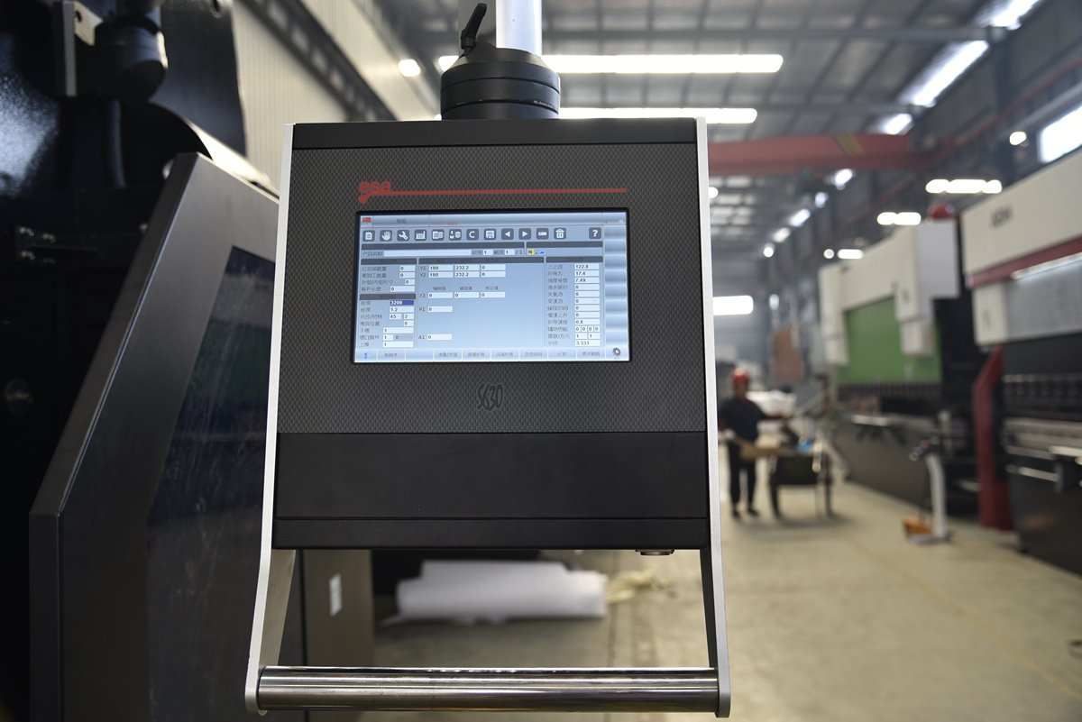
If drive technology is the “heart,” the CNC system is the brain. Its level of intelligence directly determines how quickly you move from blueprint to finished part—its value far exceeds that of a touchscreen.
- Processing Speed and Algorithms: Modern CNC controllers feature faster processors and more refined motion algorithms. This not only boosts program execution speed but also enables more precise, smoother coordination among multiple axes—Y, X, R, and more. When handling complex parts with consecutive bends, movements flow seamlessly, eliminating unnecessary pauses.
- Graphical Interface and Ease of Use: Forget cryptic code inputs. Intuitive touchscreens and 3D graphical programming allow operators to drag, visualize, and simulate bending right on the display. The system automatically checks for interference, suggests tooling, and generates optimized programs. This greatly reduces training time for new operators and minimizes trial-and-error adjustments for experienced technicians.
- Offline Programming: The ultimate weapon for maximizing throughput. The true bottleneck often isn’t bending speed—it’s idle time spent waiting for programs. Offline programming changes everything. While one machine is busy producing part A, your engineers are already preparing parts B, C, and D from their desks—complete with simulation and optimization. As soon as the machine is free, the new program can be uploaded instantly. With tooling swapped, production resumes immediately, achieving near zero downtime between jobs. By removing programming time from the machine’s schedule, this strategy is central to maximizing OEE (Overall Equipment Effectiveness).
3.3 Safety System: The Overlooked "Governor of Speed"
Safety light curtain systems are often mistaken for speed limiters. In fact, modern intelligent safety designs serve as the true governors of speed—ensuring absolute safety while intelligently unlocking high-speed operation. In premium models, they even become a defining source of performance advantage.
- Faster reaction = later deceleration: As discussed in Chapter 2, the total response time of a safety system—from detection to complete ram stop—directly determines the “speed change point” where deceleration must begin. A top-tier safety system equipped with a high-speed PLC and ultra-fast valve set can react in mere tens of milliseconds. This means it can safely allow the ram to maintain full speed until it’s closer to the workpiece before slowing down, effectively reclaiming precious milliseconds on every cycle.
- Blanking and Muting: These two capabilities are essential for unlocking high-speed bending of complex parts.
- Blanking: Imagine bending a box—once the first side is bent, it protrudes into the light curtain protection zone. A conventional system would halt operation at this point. With blanking enabled, the light curtain intelligently ignores that fixed, already-bent edge, allowing the ram to complete subsequent bends at full speed without interruption.
- Muting: This is a more advanced, automated, and temporary suspension of protection. For example, in robotic loading/unloading operations, the system can automatically mute the light curtain during a precise time window when the robot arm enters, and instantly restore protection once it leaves. This ensures uninterrupted automation and is fundamental to achieving high-speed, unmanned production.
Expert insight: When making a purchase, don’t just check for safety certifications—ask about response time and whether dynamic blanking/muting is supported. These factors directly determine whether your machine can achieve its theoretical speed in real-world production.
3.4 Backgauge Systems: Efficiency Multipliers for Multi-Step Operations

For parts requiring more than two bends, the backgauge’s movement speed and positioning accuracy often become the true bottleneck in the cycle time. Even with a ram that moves up and down at lightning speed, if the operator is still waiting for the backgauge to slowly crawl to its next position, speed gains are meaningless.
- Speed and acceleration: A high-speed backgauge (X-axis speeds exceeding 1000 mm/s) is crucial for cycle time. Its greatest value shines in parallel motion with the Y-axis: During the ram’s return stroke—less than a second—the backgauge races to the next bend position and locks in with precision. By the time the ram reaches the top, the backgauge is already in place, and the operator can immediately push the sheet for the next bend. This seamless synchronization virtually eliminates waiting between steps.
- Multi-axis coordination: Modern backgauges go far beyond simple X-axis (front-back) and R-axis (up-down) motion. Advanced systems feature independent Z1/Z2 axes (finger left-right movement), enabling:
- Asymmetric positioning: Position non-symmetrical flanges without manually moving the workpiece.
- Tapered bending: Z1/Z2 axes can move independently, forming an angle with the X-axis to easily bend tapered parts.
- One-stop processing: When bending multiple times along a slanted edge of a long sheet, the fingers can travel along the slope, positioning once and completing all bends in sequence—eliminating workpiece rotation and re-positioning, delivering geometric gains in efficiency.
3.5 The Hidden Costs of Chasing Maximum Speed
Finally, as a meticulous engineer, I must reveal a harsh truth: relentlessly pushing machines to their maximum speed can lead to a series of overlooked “hidden costs” that may ultimately outweigh any gains.
- Accelerated tool wear: Higher approach speeds mean stronger impact forces, while faster bending speeds increase friction and heat between tooling and sheet metal. These factors can significantly hasten the wear of expensive dies, softening or chipping punch edges. Sacrificing tool longevity for a few milliseconds of speed gain is a textbook case of misplaced priorities.
- Reduced accuracy and higher scrap risk: At extreme approach speeds, machine inertia can cause Y-axis overshoot, affecting depth control. Excessive bending speed makes springback harder to predict, reducing angle consistency. Achieving ±0.1° angle precision often delivers more value than chasing 200 mm/s rapid traverse. A single rework or scrap piece can cancel out the time savings from dozens of cycles.
- Machine lifespan and maintenance: Constantly running at redline is like driving a car at maximum revs all the time. It accelerates frame fatigue and wear on hydraulic or servo drive systems, driving up maintenance costs and shortening machine life. Smooth, optimized speed profiles are far healthier for your long-term assets than brute-force sprinting.
Key takeaway: True speed is the combined result of drive technology, CNC systems, safety systems, and backgauge performance. It’s not a single peak figure, but the ability to achieve the shortest cycle time per part while maintaining precision, safety, and low costs. Once you grasp this, you hold the key to evolving from a mere “speed user” to a master “efficiency conductor.”
IV. Practical Playbook: Four Steps to Maximize Production Efficiency
Knowledge is worthless if it doesn’t translate into profits on the shop floor. You now understand both the macro and micro factors affecting press brake speed—now it’s time to forge these insights into a systematic approach that transforms your machine from a simple processing tool into a profit-generating asset.
This four-step optimization method is a standard operating procedure (SOP) distilled from our team’s consultancy work with hundreds of top-tier manufacturers worldwide. It guides you from diagnosing bottlenecks, to quantifying gains, fine-tuning parameters, and ultimately building a self-evolving system of continuous improvement.
4.1 Step One: Diagnose Your Core Production Tasks
Optimization starts with precise diagnosis. Before touching any CNC parameter, you must approach your production tasks like an experienced doctor conducting a thorough check-up.
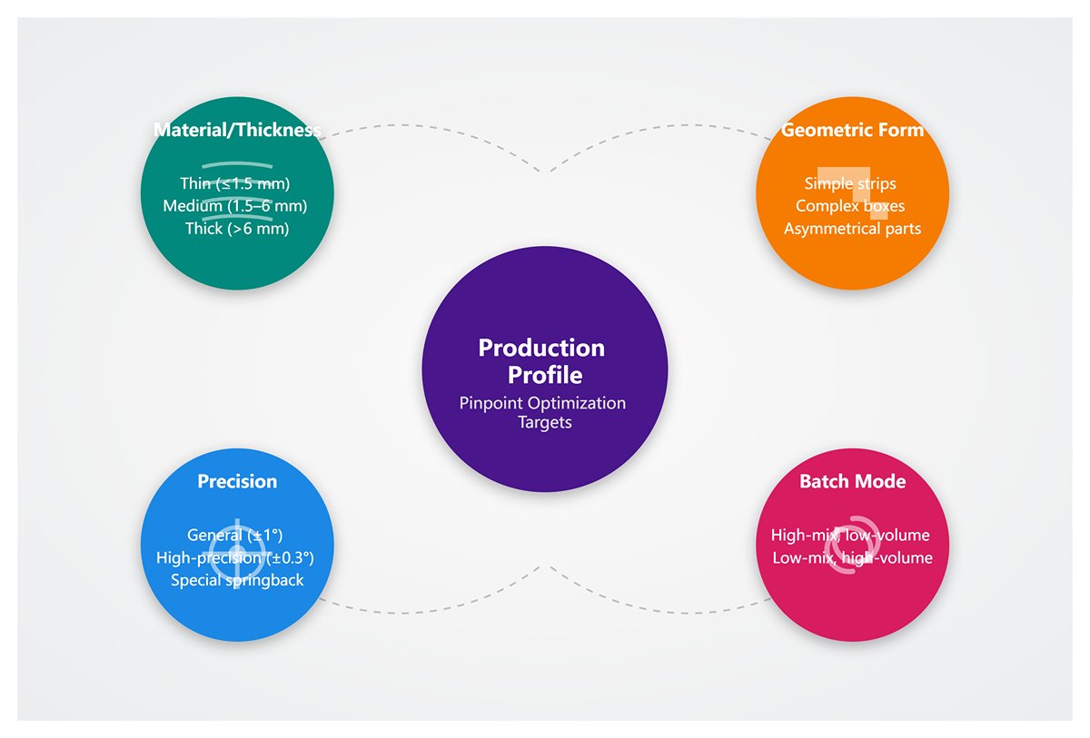
- Create a production profile and pinpoint optimization targets: Begin by categorizing the parts you process daily. Don’t just see them as sheets of metal—profile them using these dimensions:
- Material and thickness groups: Thin sheet (≤1.5 mm), medium plate (1.5–6 mm), thick plate (>6 mm)?
- Geometric form groups: Simple long strips, complex multi-flange boxes, asymmetrical or tapered parts?
- Precision requirement groups: General structural parts (±1°), high-precision aesthetic parts (±0.3°), parts with special springback characteristics?
- Batch mode: High-mix, low-volume (frequent tooling changes)? Or low-mix, high-volume (long continuous runs)?
For each group, set a clear optimization goal: is it cycle time per part? First-pass yield? Or changeover preparation time? This ensures your efforts focus on areas with the highest payoff.
- Conduct a stopwatch time study to break down production rhythm: Select a representative high-frequency part, grab a stopwatch (or record with your phone), and dissect every motion with the precision of an F1 pit crew:
- Y-axis pure processing time: Fast approach, working stroke (including dwell and decompression), return stroke.
- X/R/Z-axis waiting time: Idle time at the top of the stroke while the backgauge moves into position.
- Human-operated time: This includes the operator turning to collect material, pushing sheets to the back gauge, flipping or rotating the workpiece, removing finished products, and stacking them.
- Preparation and auxiliary time: Tasks such as changing dies, loading programs, performing the first test bend and measurement, and adjusting compensation values.
Record these time figures in a simple table. You might be surprised to discover that the real “time sink” often isn’t the machine’s bending speed, but the seemingly trivial delays from back gauge waiting and workpiece flipping. These are your top-priority targets for improvement.
- Identifying the “Invisible Killer”: Setup Time: For factories producing a wide variety of small batches, the true efficiency killer is setup time. Here, you need to introduce two powerful lean manufacturing tools:
OEE (Overall Equipment Effectiveness): Using the formula:
You can quickly calculate your equipment’s “health score.” A low OEE usually points directly to excessive downtime caused by setup.
SMED (Single-Minute Exchange of Dies): The core idea is to convert “internal setup time” (tasks that require stopping the machine, such as unscrewing bolts) into “external setup time” (tasks that can be prepared while the machine is running, such as staging the next set of dies and programs). Implementing quick-clamp systems, a modular die library, and offline programming software will yield far greater benefits than simply increasing the approach speed by 10 mm/s.
Once you’ve completed this step, you’ll have a precise diagnostic report that clearly identifies the major sources of efficiency loss.
4.2 Step Two: Quantifying Your Cycle Time Potential
The end of diagnosis marks the beginning of potential quantification. Before investing in any modifications or optimizations, you must use data to answer one critical question: “Is it worth doing?”
Build your “Digital Takt Model”: Based on the measurements from step one, we can create a simplified mathematical model to estimate the theoretical time for a single bend. Single bend time
where:
represent the approach, bending, and return times respectively.
is the additional back gauge movement wait time that cannot be overlapped with the Y-axis return.
is the additional manual handling time that cannot be overlapped with machine movements.
Perform a “Three-Point Comparison” to reveal gaps and opportunities: For your representative parts, calculate three key metrics:
- As-Is: Directly use the real-world measurements from step one.
- Theoretical Minimum (To-Be Theoretical): Use the maximum speeds listed in the equipment manual, assuming complete parallelism between back gauge movement and manual handling (i.e., net waiting time = 0). This is the unreachable “North Star” you can always strive toward.
- Improvement Target (To-Be Realistic): Based on your machine’s capabilities, calculate a realistically achievable goal by optimizing safety settings, smoothing speed transitions, and maximizing parallel back gauge movement.
4.3 Step Three: Mastering CNC Speed Parameter Settings
Now we move into the heart of the battle—the CNC control panel. Every setting here is a note in the symphony of your production rhythm. Approach it like a conductor, fine-tuning each movement with precision.
- Approach Phase (Y-Axis Approach):
- Goal: Minimize unloaded travel time while ensuring smooth contact.
- Settings:
- Set the approach speed ($v_1$) to the safe maximum allowed by your equipment (e.g., 180–220 mm/s).
- Key optimization: Adjust the “speed change point” to be as low as safely possible. This requires consultation with your equipment supplier and optimization of safety light curtain response time and masking functions.
- Advanced tip: Insert a brief deceleration segment before the speed change point to achieve a “soft landing,” eliminating impact on the die and protecting both tooling and workpiece surfaces.
- Bending Phase (Y-Axis Bending):
- Goal: Maintain angle precision and consistency while preventing surface damage.
- Settings:
- Segmented speed approach: For parts with high precision requirements, split the bending process into two stages. Use a moderate speed (e.g., 10–15 mm/s) for the bulk of the stroke, then switch to an ultra-slow “finishing” speed (e.g., 1–3 mm/s) for the last 1–2 mm to guarantee exact angles.
- Optimize dwell and decompression: Keep only the “minimum necessary” dwell time ($t_{\text{dwell}}$) to control springback. Consult the supplier to implement a smoother “second-order decline” decompression curve ($t_{\text{decomp}}$) that maintains angle stability while reducing decompression time.
- Return Phase (Y-Axis Return):
- Goal: Create a “parallel operation window” for the next cycle.
- Settings:
- Set the return speed ($v_3$) to its maximum value.
- Key Optimization: In the CNC program, ensure the backgauge movement command is issued the instant the Y-axis begins its return stroke. This is the critical step to achieving "zero waiting".
- Work closely with the operator to train the "removal of the workpiece" action to occur within the safe window while the ram is ascending.
- Backgauge Strategy:
- Objective: Eliminate waiting time between process steps.
- Settings:
- Set the acceleration and speed of the X/R axes to the maximum allowed, and enable the "Look-ahead" function.
- For multi-axis systems (e.g., X, R, Z1, Z2), ensure the CNC uses the logic "asynchronous positioning, determined by the slowest axis" rather than waiting for all axes to complete before issuing the positioning signal.
4.4 Step Four: Testing, Measurement, and Continuous Improvement

Optimization is a marathon without a finish line, not a 100-meter sprint. Establishing a closed-loop improvement system is the only way to turn today’s gains into tomorrow’s standard.
- Create "golden sample programs" and SOPs: For every frequently produced part that has been successfully optimized, lock in its parameters, sequence, and tooling combinations as an immutable "gold standard program." Develop a richly illustrated SOP (Standard Operating Procedure) to ensure any operator can replicate best practices with 100% consistency.
- Base decisions on data, not intuition: Regularly collect key metrics—single-piece cycle time, first-pass yield rate, CPK values for angles and dimensions (target ≥ 1.33). Any downward trend in these figures should be treated as an early warning from the system.
- Run rapid, incremental A/B tests: When trying a new optimization (e.g., reducing hold pressure by 0.05 seconds), follow a scientific testing method: within the same batch, produce 10 pieces with the old parameters and 10 with the new ones, then compare angle variation and surface quality. Update the "golden sample program" only when the data shows a clear net gain.
- Make maintenance and calibration routine: Stable speed depends on machine health. Include checks for machine parallelism, backgauge clearance, hydraulic oil temperature and cleanliness, and safety system response time in weekly and monthly maintenance lists. A machine in peak condition is the foundation for all optimization.
- Make improvements visible: Set up a "production rhythm board" on the shop floor to display the day’s target pace, actual pace, and the gap in real time. This visual management approach fosters team pride and motivation, turning continuous improvement from a task into a shared culture.
By following these four steps, you’ll move beyond fixating on the simple question of “how fast can the press brake go.” You’ll become a true "orchestrator of productivity," precisely coordinating every beat of people, machines, materials, methods, and environment—playing your own symphony of profit growth in a fiercely competitive market.
V. Summary
In conclusion, a press brake's true value lies not in its top speed, but in its overall production rhythm. Maximizing efficiency requires a holistic approach—optimizing the entire bending cycle by mastering the interplay of drive technology, CNC systems, and automation. This transforms your machine from a simple tool into a highly profitable production asset.
For a deeper understanding of how different machine models and configurations can enhance your workflow, explore ADH’s latest Brochures to learn more about flexible solutions available for your production line.
Ready to move beyond raw speed and unlock your true production potential? The experts at ADH can help you diagnose bottlenecks and engineer a tailored solution. Contact ADH today for a consultation to elevate your manufacturing efficiency, or simply contact us to start discussing your specific production challenges.
VI. FAQ
Q: Should I set the bending speed (work advance speed) to the maximum to boost output?
A: In most cases, that’s wrong. This is perhaps the number one pitfall in efficiency optimization. For most parts, the main bottlenecks in total cycle time are: 1) the Y-axis non-loaded travel (approach and return strokes); 2) backgauge waiting time between bends; 3) manual handling. Blindly increasing bending speed contributes little to overall time and often harms angle accuracy, increases scrap rates, and leads to rework—resulting in negative optimization. The correct sequence is: first, reduce non-loaded travel time by optimizing safety systems and programs; second, eliminate backgauge waiting through parallel programming; and only then, slightly increase bending speed while maintaining quality.
Q: Are all-electric servo press brakes always faster and better than hydraulic ones?
A: It depends on the scenario, not an absolute rule. For thin sheet, multi-bend, high-rhythm production, all-electric servos excel with lightning-fast start/stop responsiveness and strong acceleration/deceleration, cutting single-piece cycle time by over 25% and delivering significant energy savings. However, for thick plate, high-tonnage, long hold-pressure applications, robust hydraulic or hybrid systems still hold advantages in cost, durability, and power output. Your choice should be based on your "production profile," not on chasing a technology label.
Q: Can I disable or bypass the safety light curtain to gain speed?
A: Absolutely not—this is both deadly and wrong! Not only is it a serious safety violation, but it’s also a misunderstanding of efficiency. Modern intelligent safety systems are enablers of speed, not limiters. Their key value lies in reaction time. A top-tier system with a high-speed PLC and sensitive light curtain can legally shorten the mandatory safety slowdown distance, allowing the ram to run at high speed for more of its stroke. The right path is to optimize the safety system (e.g., using mute or shield functions), achieving both speed and safety.


