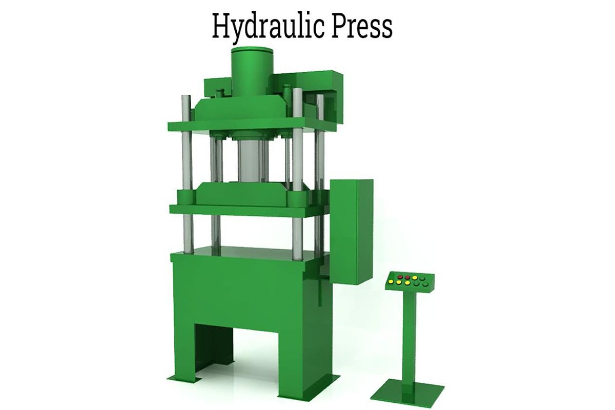
The question, "How hard can a hydraulic press push?" seems simple, but the answer unfolds into a fascinating story of industrial power. It's a journey that takes us from small benchtop units producing a few tons of force to colossal, multi-story machines capable of exerting tens of thousands of tons—enough to shape the massive metal components used in aerospace and national defense.
However, the true force of any press is not a single number on a specification sheet. It is the result of a delicate interplay between hydraulic pressure, cylinder size, and the immense structural strength of the machine's frame.
This guide will move beyond the theoretical to give you a complete, practical understanding. We will deconstruct the core principles, provide a clear method for calculating real-world force, and reveal the hidden factors that can diminish—or enhance—your machine's true power, empowering you to safely and effectively command its full potential.
I. Core Question Analysis: How Much Force Can a Hydraulic Press Really Exert?
The hydraulic press is both the muscle and the backbone of modern industrial civilization. From precise laboratory setups to massive forging operations, its range of power is vast enough to reshape the material world itself. To truly grasp this power, we must start with a direct answer, trace it back to its physical origins, and finally unveil the full meaning behind the industry's favorite term—“tonnage.”
1.1 The Short Answer: A Spectrum of Power from Desktop to National Scale
The simple truth is that the output force of hydraulic presses spans an astonishing range—from a few tons for light-duty applications to over 80,000 tons for strategic-level forging. It’s not a single number, but a spectrum of power that covers nearly every manufacturing need imaginable.
To give you a more tangible sense of scale, the table below compares different classes of hydraulic presses by capacity and application:
| Class | Typical Tonnage Range (short tons, 1 ton = 2,000 lbs) | Typical Applications | Perceptual Analogy |
|---|---|---|---|
| Desktop/Laboratory | 1 – 40 tons | Material sample pressing, small-part assembly, lab pressure testing. | Like using the force of a single fingertip to flatten a car. |
| Workshop/Automotive | 20 – 150 tons | Bearing and gear assembly/disassembly, medium sheet-metal bending, stamping, or straightening. | Powerful enough to lift an entire loaded subway car (around 60 tons) with ease. |
| Standard Industrial | 150 – 2,000 tons | Deep drawing of car doors and hoods, large-structure blanking, compression molding. | Equivalent to concentrating the full weight of an adult blue whale (about 200 tons) onto a die surface. |
| Heavy Forging/National Scale | 2,000 – 80,000+ tons | Aerospace (wing spars, rocket engine parts), nuclear (reactor pressure vessels), shipbuilding (giant propellers). | The largest U.S. forging press delivers 80,000 tons of pressure—enough to mold multi-meter-thick steel ingots as if they were dough. |
Key Insight: The upper limit of hydraulic press power is constrained only by the frontiers of materials science and engineering design. It’s not a fixed ceiling—it evolves alongside the progress of human industry.
1.2 The Source of Power: The Engineering Genius of Pascal’s Law
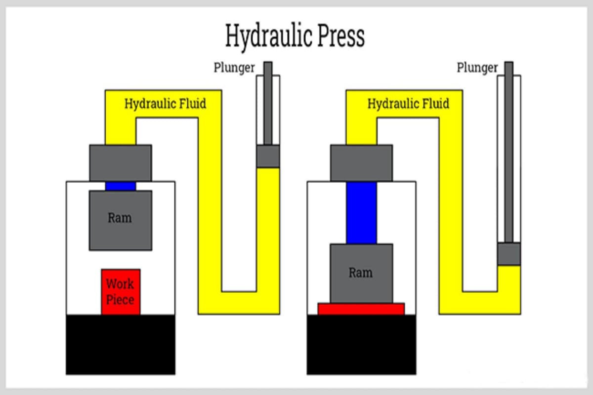
The hydraulic press’s ability to “multiply force” doesn’t come from electronics or chemistry, but from a timeless principle of classical physics discovered in the 17th century—Pascal’s Law.
- Core Principle: This law states that any pressure applied at a single point to a sealed, incompressible fluid—such as hydraulic oil—will be transmitted, unchanged in magnitude, to every point within the fluid and to every part of the container walls.
- Force Multiplication Mechanism: Picture two pistons of different sizes connected by a pipe. When a smaller force, denoted as $F_1$, is applied to the smaller piston (with surface area $A_1$), it generates a pressure in the hydraulic fluid given by $P = F_1 / A_1$. According to Pascal’s law, this pressure $P$ is transmitted without loss to the base of the larger piston (surface area $A_2$). Consequently, the amplified output force $F_2$ exerted by the larger piston equals this pressure multiplied by its much greater area:
Because the larger piston’s area $A_2$ is significantly greater than that of the smaller piston $A_1$, the output force $F_2$ is precisely amplified by a factor of $(A_2 / A_1)$.
Memorable Takeaway: Pressure is the messenger of force, and area is the amplifier. That’s why a relatively small hydraulic pump can drive a cylinder generating thousands of tons of force—this simple idea is the foundation of all hydraulic technology.
1.3 The True Meaning of “Tonnage”: From Trade Term to Physical Quantity
In the world of hydraulic presses, “tonnage” is not merely a sales spec—it is the defining indicator of a machine’s capability, connecting commercial language with engineering reality.
- Definition: Tonnage refers to the maximum rated static force a hydraulic press can deliver at its design limit. It represents the machine’s capacity ceiling—its industrial identity card.
- Unit Clarification: Units matter. In the U.S. and regions following its system, 1 ton usually means one short ton, equal to 2,000 pounds (lbs) of force. In the metric system, 1 metric ton (tonne) equals about 2,204.6 pounds. This subtle difference becomes critical in precision engineering or international procurement.
- Physical Essence: Tonnage isn’t an arbitrary commercial figure—it’s a calculable physical quantity derived from two key parameters of the hydraulic system: maximum system pressure and the main cylinder’s piston area. It perfectly embodies the principles outlined earlier, transforming them into a standardized language for technical communication.
This prepares us for the next chapter, where we’ll decode the “golden formula” behind these relationships—empowering you to determine a hydraulic press’s core strength using only a few essential parameters.
II. Underlying Logic: Unveiling the Mechanism Behind Hydraulic Thrust
The immense power of a hydraulic press isn’t magic—it’s built on clear physical principles and precise engineering design. Understanding how thrust is generated transforms you from a mere operator into a true master of the machine.
We’ll start with a fundamental formula, explore the three engineering pillars that support it, and dispel some common—and potentially dangerous—misconceptions.
2.1 The Golden Formula: Force (F) = Pressure (P) × Area (A)
Every ounce of hydraulic power stems from this elegant yet powerful equation—the “genetic code” of hydraulic systems. It defines the unbreakable link between three core variables:
- Force (F): The ultimate thrust output of the press, often referred to as its “tonnage.” This is the result we aim to achieve.
- Pressure (P): The intensity generated by the hydraulic pump station within the sealed system, similar to water pressure. Common units include PSI (pounds per square inch) or MPa (megapascals).
- Area (A): The effective cross-sectional area of the main cylinder’s piston—the stage upon which pressure performs.
Key Insight: The final thrust is essentially the sum of pressure applied evenly across the piston’s large surface area. This is Pascal’s Law at its most brilliant—multiplying force.
Professional Calculation Example: Imagine an industrial-grade hydraulic press with a maximum system pressure of 3,000 PSI and a piston diameter of 10 inches.
Calculate Piston Area (A): Area magnifies force.
Calculate Maximum Force (F): Apply pressure across the area.
Convert to Engineering Tonnage: Translate physical units into common terms.
Thus, this machine is rated at roughly 118 tons. This formula is the cornerstone for evaluating, designing, or troubleshooting any hydraulic system.
2.2 The Three Pillars of Thrust: System Pressure, Cylinder Size, and Structural Strength
While the golden formula is simple, turning theoretical power into dependable industrial performance depends on three robust engineering pillars. Together, they define the real-world limits of a hydraulic press.
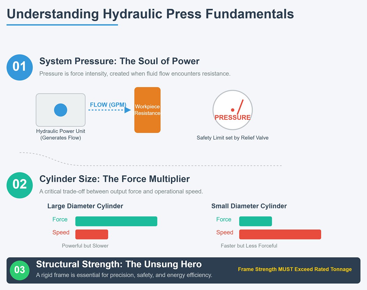
- Pillar One: System Pressure (P) – The Soul of Power System pressure is the “intensity” or “density” of force, supplied by the Hydraulic Power Unit (HPU). It’s important to note: pumps generate flow (GPM—gallons per minute), not pressure. Pressure builds only when flow encounters resistance, such as contact with a workpiece. The upper limit of pressure is set by the relief valve—the system’s safety sentinel—preventing pressure from exceeding design limits and safeguarding the entire system.
- Pillar Two: Cylinder Size (A) – The Force Multiplier At constant pressure, a larger piston area yields greater output force. Like a lever, it converts fluid pressure into massive mechanical thrust. However, there’s a crucial force-speed trade-off. A large-diameter cylinder delivers huge force but requires more fluid to move each inch. With pump flow fixed, large cylinders are powerful but slower, while smaller cylinders are faster but less forceful. Choosing the right cylinder size is an art of balancing strength and efficiency.
- Pillar Three: Structural Strength – The Unsung Hero Often overlooked, yet decisive. The tremendous force generated must be absorbed and directed by the machine’s frame—bed, columns, and upper beam. If the frame lacks rigidity, high loads cause deflection, degrading precision, wasting energy, and in extreme cases, leading to catastrophic failure. An exceptional press must have a frame strength far exceeding its rated tonnage to ensure safe, precise transmission of force to the workpiece.
2.3 Clearing Common Misconceptions: Debunking Four Myths About Hydraulic Thrust
Misunderstanding is more dangerous than ignorance. In hydraulics, the following four myths are widespread and must be corrected.
- Myth One: Hydraulic presses can “multiply pressure.” Fact: This is one of the most common misinterpretations of Pascal’s Law. Hydraulic systems do not multiply pressure; in a sealed liquid, pressure is equal throughout. What the press actually multiplies is force—by applying a small force to a small piston area to create pressure, then transmitting that constant pressure to a larger piston area, resulting in amplified force output.
- Myth Two: More horsepower (HP) means more tonnage. Fact: Horsepower and tonnage are not directly equivalent. Horsepower determines the rate of work—the product of force and speed. A more precise relation is
HP ≈ (GPM × PSI) / 1714. Thus, two presses rated at 200 tons will differ: the one with higher horsepower has greater pump flow (GPM), enabling faster slide movement and pressing speed, and thus higher productivity. - Myth Three: The pressure gauge reading (PSI) equals output tonnage. Fact: The gauge shows the hydraulic fluid’s internal pressure (PSI)—the raw material of force, not the finished product. Multiply the pressure reading by piston area and convert units to find actual output tonnage. A handy rule: if the gauge reads 50% of maximum set pressure, the current output force is roughly 50% of the machine’s rated tonnage.
- Myth Four: A 100-ton press always operates at 100 tons of force. Fact: 100 tons is the maximum capacity, not a constant state. A hydraulic press outputs only the force needed to overcome the workpiece’s resistance. For example, bending a thin aluminum sheet may require just 10 tons, with system pressure automatically stabilizing at a much lower level. Only as the workpiece’s resistance increases will pressure rise, up to the set limit (the PSI corresponding to 100 tons).
III. Practical Calculation & Assessment: Accurately Determining Your Press’s Thrust
Theory provides the blueprint, but hands-on calculation transforms that blueprint into a precise, measurable reality. This chapter takes you from the realm of abstract principles to the workshop floor.
Step by step, we’ll break down how to translate equipment specifications into actual tonnage calculations, uncover the subtle factors that erode theoretical strength in practice, and reveal the invisible safety boundaries that keep operations secure.
3.1 The Four-Step Precision Method: A Professional Guide from Parameters to Tonnage
Master this four-step process, and you’ll possess the “decoder” for evaluating any single-action hydraulic press. It transforms cold numbers on a nameplate into the tangible force you can truly feel.
Step 1: Identify the Two DNA Elements of Force — Key Data Collection
Every accurate calculation starts with two fundamental datasets. They can usually be found in the machine’s specification manual, on its metal nameplate, or measured directly when necessary:
- Maximum System Pressure (P): This represents the “pulse strength” of the hydraulic system, defined by the relief valve—essentially the pressure ceiling. It’s measured in PSI (Pounds per Square Inch), describing the density of the applied force.
- Main Hydraulic Cylinder Diameter (d): This is the “amplifier” of force—the stage on which pressure performs. It’s measured in inches and refers specifically to the primary cylinder responsible for applying thrust, not the smaller one that handles the return stroke.
Step 2: Build the Stage for Power — Calculating Piston Area (A)
Area is the cornerstone where Pascal’s Law works its “magic.” Using the standard formula for the area of a circle, first convert diameter to radius (r = d/2), then calculate this critical effective surface:
Step 3: Unleash Theoretical Potential — Calculating Ideal Thrust (F)
By applying pressure evenly across that surface area, you obtain the machine’s maximum theoretical thrust—its pure performance under ideal, frictionless conditions. The result is expressed in pounds (lbs):
Step 4: Translate Physics into Industrial Terms — Converting to Tonnage
For easier industry reference, convert pounds to tons. Under U.S. standards, one short ton equals 2,000 pounds; in the metric system, one metric ton (tonne) equals approximately 2,204.6 pounds. We’ll use the U.S. standard here:
Practical Example: Dissecting a 226-Ton Hydraulic Press
Let’s assume you’re working with a press that has the following specifications:
- Maximum System Pressure (P) = 4,000 PSI
- Main Cylinder Diameter (d) = 12 inches (thus radius r = 6 inches)
Calculate Area A:
Calculate Thrust F:
Calculate Tonnage T:
Conclusion: The machine’s theoretical rated capacity is 226.2 tons.
Insight to Remember: The pressure gauge is essentially your live force indicator. If the gauge reads 50% of the set maximum pressure, you’re currently delivering 50% of the machine’s rated tonnage.
3.2 Beyond Theory: Factoring in Efficiency Loss and the Safety Factor
That 226.2-ton figure represents its ideal, lab-grade performance. But in the real industrial world, we must incorporate two critical correction factors.
- Efficiency Loss: The Unavoidable “Energy Tax”
A hydraulic system is not a perpetual motion machine—energy loss is inevitable, much like the costs of logistics. This “energy tax” primarily comes from:- Mechanical friction between pistons, cylinder walls, and sealing components.
- Fluid friction, caused by hydraulic oil resisting flow through complex pipelines, valves, and bends.
- Internal leakage, even within precision-engineered pumps, valves, and cylinders. Microscopic gaps allow high-pressure oil to “escape,” reducing both pressure and flow effectiveness.
Most of that energy loss eventually turns into heat, which explains why a hydraulic power unit gets warm after extended operation. A well-maintained industrial hydraulic system typically operates at 80% to 90% efficiency. Thus, a more realistic formula for calculating actual tonnage is:
Taking our 226.2-ton press example with a total system efficiency of 85%, the effective maximum thrust delivered to the workpiece is approximately:
This roughly 34-ton difference is the “tax” reality imposes on the laws of physics.
- Safety Factor: The Invisible Structural Insurance
This is a crucial yet often misunderstood concept. The safety factor is not a discount multiplier in your calculations—it’s the built-in reserve of structural strength engineered by the manufacturer.- Its True Role: It’s a form of construction insurance purchased for you at the design stage by engineers. A 2:1 safety factor means the machine’s frame (body, columns, beams) can withstand twice its rated load before yielding or permanently deforming.
- Its Core Purpose: To ensure structural integrity and operational safety under full-load, off-center, or impact conditions. It also minimizes structural deflection—essential for maintaining precise machining tolerances.
- Why you can't use it for calculations: The safety factor is a proprietary design parameter held by the manufacturer. It defines the machine’s “survivability limit,” not your everyday operating range. Any attempt to push operations to the edge of the safety factor is essentially a high-stakes gamble with catastrophic structural failure.
Key Insight: As an operator, your primary concern should be efficiency losses, because these determine the actual usable force you can apply. The safety factor, on the other hand, defines how reliable the machine remains under extreme conditions—it’s the safeguard that keeps operations within the boundaries of structural safety.
IV. Advanced Optimization: Real-World Factors and Strategies for Surpassing Theoretical Limits
Theoretical calculations sketch an impressive vision of potential force, but the final stretch towards peak performance is littered with invisible obstacles. Throughout its lifespan, a hydraulic press rarely achieves its full theoretical output.
Understanding and overcoming the real-world factors that erode performance is key to elevating a merely “adequate” machine into an “exceptional” production asset. This chapter exposes these unseen adversaries and offers a systematic approach to restore, maximize, and safely realize your equipment’s full potential.
4.1 The Invisible Adversaries: Three Primary Culprits Behind Reduced Actual Force
In any hydraulic system, a gap inevitably exists between theoretical force and actual output. These silent performance killers quietly convert massive theoretical force into wasted heat. The gap is primarily caused by three culprits:
Internal and External Leakage: Direct Thieves of Power — This is the most immediate and common way force is lost.
- External leakage: Highly visible, often appearing as oil stains or drips, typically at hose fittings, cylinder seals, or valve block connections. Beyond wasting costly hydraulic oil and polluting the environment, it directly prevents the system from building or maintaining sufficient pressure—much like a leaking tire can’t support a car.
- Internal leakage (Internal Bypass): Far more subtle yet deadly. Occurs in cylinder piston seals, valve spools, or within pumps, where high-pressure oil bypasses directly to the low-pressure circuit or reservoir without doing any work. You’ll see no oil leaks, but the machine will move sluggishly, feel weak, or fail to hold position under load. This internal loss is a key driver of system overheating and rapid efficiency decline.
Fluid Contamination & Degradation: The Breakdown of the System’s Lifeblood — Hydraulic oil is the system’s “blood,” and its condition directly determines both power transmission efficiency and service life.
- Particulate contamination: Dust, metal shavings, and other microscopic debris act like liquid sandpaper, circulating through the mating surfaces of precision components (pumps, valves, cylinders) and causing irreversible wear. Over 75% of hydraulic system failures are directly linked to oil contamination.
- Oil oxidation and overheating: When oil temperatures consistently exceed the ideal operating range (typically above 80°C), oxidation accelerates, viscosity drops, lubrication quality declines, and sludge forms, clogging filters and fine valve ports. Overheated oil is itself a symptom of inefficiency (often due to severe internal leakage), creating a vicious cycle.
- Air and water contamination: Air in the oil can cause cavitation, producing tiny implosions inside the pump that strike metal surfaces like miniature hammers, leading to pitting damage. Water contamination emulsifies the oil, stripping away its lubrication properties and corroding components.
Mechanical & Flow Losses: The System’s Built-In Energy Tax — These losses are inherent to system design, impossible to eliminate entirely but possible to optimize.
- Mechanical friction: The friction between cylinder piston seals and barrel walls, as well as among moving components, directly consumes part of the available force—especially during startup.
- Flow resistance (pressure drop): As hydraulic oil travels through long or winding pipes, narrow valve ports, and filters, it loses pressure due to resistance. Much like water in a long, thin hose, the pressure at the far end is always lower than at the source. Longer, narrower pipes with more bends result in greater pressure loss.
4.2 Performance Enhancement Strategies: Restoring and Maximizing Equipment Force
Defeating these culprits is less about repairing equipment and more about managing the health of a sophisticated fluid system. The following strategies will help you convert theoretical force into real-world productivity.
Implement Preventive Maintenance Centered on Oil Analysis
- Conduct regular oil sampling and analysis: This is like running a “blood panel” for your machine. Professional oil analysis reveals cleanliness levels (ISO 4406), moisture content, viscosity changes, and concentrations of wear metals—allowing you to detect failures (like abnormal bearing wear) before they happen.
- Follow a strict filter replacement schedule: Never wait for the filter blockage warning to light up. A partially clogged filter is a prime cause of pressure drop and pump overload. Treat filter replacement as an investment, not an expense.
Optimize System Design and Component Selection
- Upgrade critical seals and hoses: When replacing, choose higher-quality, more wear-resistant, and heat-tolerant seals and hoses to significantly extend leak-free operating periods—an investment with excellent cost-effectiveness.
- Consider a variable displacement pump: Unlike fixed pumps that run at full speed constantly, variable pumps adjust flow output based on load requirements. In standby or low-load conditions, they dramatically cut energy use and heat generation, boosting system efficiency at its source.
- Use accumulators wisely: In applications requiring sudden high flow or steady pressure retention, an accumulator stores high-pressure oil and releases it quickly when needed, helping the pump handle peak demand, reducing pump size, and absorbing pressure spikes to protect the system.
Refined Thermal Management
- Keep coolers performing efficiently: Regularly clean cooler fins—whether air or water-cooled—to ensure unobstructed airflow or water circulation.
- Maintain optimal oil temperature stability: Keep oil temperature within the recommended range (typically 45–60°C). Stable temperature means stable viscosity, which is the foundation for precise, repeatable pressure control.
4.3 Safely Achieving Maximum Force
Operating a machine near its rated tonnage tests more than just the equipment—it challenges the operator’s knowledge and the system’s protective measures. Maximum force is a double-edged sword: one side delivers unmatched productivity, the other teeters on the brink of structural failure.
Deeply Understand and Trust the Hydraulic Overload Protection System (HOLP)
- HOLP is typically installed inside the ram and serves as the final safeguard for both the machine and the tooling. When the actual load—perhaps due to double-feeding or incorrect die adjustment—exceeds the preset tonnage by 10–15%, it vents cylinder pressure within milliseconds, instantly stopping or retracting the ram.
- Its core mission is to safeguard the high-value dies and molds—often worth far more than the press itself—and prevent permanent plastic deformation of the machine frame. It must be tested regularly to ensure proper function, and operators should be trained on how to correctly reset the system after an overload event.
Use precise load monitoring instead of relying on pressure gauges
- A pressure gauge reflects only hydraulic line pressure; it cannot indicate the actual force applied to the workpiece or detect off-center loading.
- For precision forming or operations near the tonnage limit, strain gauges or load cells integrated into the press columns or beneath the die are essential. These sensors provide real-time, highly accurate force feedback, allowing operators to work with surgical precision even at the performance edge—while simultaneously monitoring load distribution at all four corners.
Maintain absolute vigilance over structural rigidity and eccentric loading
- Always remember that the ultimate limit of a press is its frame rigidity. Even if the hydraulic system can generate greater force, excessive frame deflection renders that force both ineffective and potentially harmful, severely compromising product accuracy.
- Eccentric loading is strictly prohibited. Position the workpiece as close to the geometric center of the table as possible. Severe off-center loading causes ram tilting, which can permanently damage guide accuracy and impose destructive stress far beyond rated capacity on a single column—one of the most common causes of frame cracking.
V. Conclusion
In the end, the question "How hard can a hydraulic press push?" leads to a much deeper understanding than a simple tonnage rating. The true force of a press is a dynamic interplay between the theoretical power derived from Pascal's Law (Force = Pressure × Area) and the realities of engineering.
We've seen that this force is supported by the three pillars of system pressure, cylinder area, and—most critically—the structural integrity of the machine's frame. The ideal force is always diminished by real-world efficiency losses from friction and leaks, but this lost power can be recovered through diligent maintenance and system optimization.
Ultimately, mastering your press's power means calculating its ideal force, accounting for its inefficiencies, and safely operating within the structural limits protected by its safety systems. For more background on the equipment itself, you can explore what a press brake is and how it relates to hydraulic press operations.
Understanding the principles behind your hydraulic press is the first step. Applying that knowledge to maximize your operational force and efficiency is where true value is created. If you're ready to bridge the gap between theory and tangible results, the experts at ADH are here to guide you.
We can help you accurately assess your equipment's capabilities, identify performance bottlenecks, and implement strategies to ensure you are getting every ton of force you paid for, safely and efficiently. You can also browse our detailed Brochures to learn more about our range of solutions and technical specifications. Contact us today for a comprehensive force audit and consultation. Let us help you unlock the full, uncompromised power of your hydraulic press.


