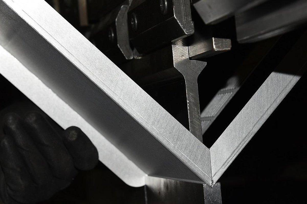
In any fabrication shop, understanding the press brake bending force is not just an academic exercise—it is the very foundation of safe, efficient, and profitable manufacturing. Relying on guesswork or "tribal knowledge" to determine the force needed for a job is a high-stakes gamble that risks damaging expensive machinery, destroying valuable tooling, and producing inconsistent, low-quality parts.
This guide is designed to replace that uncertainty with scientific precision. We will move beyond empirical methods to provide a comprehensive framework for mastering bending force calculation.
From deconstructing the core formulas and exploring the critical variables that influence them, to providing a step-by-step practical guide, you will learn not only how to calculate the required force but why it is strategically vital.
By the end, you will be equipped to transform your approach from a reactive operator to a proactive optimizer, ensuring every bend is a perfect blend of safety, quality, and efficiency.
I. Strategic Awareness: Why Accurate Bending Force Calculation Is the Lifeline of Sheet Metal Processing
In the realm of precision metal forming, experience is a valuable asset, yet relying on experience alone is like walking along the edge of a cliff. A single “by feel” operation that seems harmless might sow the seeds for equipment failure, product scrap, or even safety accidents.
Calculating the bending force is far more than a sterile engineering formula—it forms the bridge between theory and practice, the strategic pivot that ensures production remains safe, precise, efficient, and cost-effective. To ignore it is to overlook the very foundation of the entire sheet metal process.
This article will completely reshape how you think about bending force calculation. It is not a dry list of parameters, but a strategic framework designed to strengthen your professional decision-making. We’ll start from the strategic question of why we calculate, building a knowledge system that’s as robust as it is actionable.
1.1 Beyond Experience: The Four Core Values of Bending Force Calculation
Accurate bending force calculation is far from an academic indulgence—it directly imbues the production process with four indispensable core values.
- Safety Cornerstone: Protecting Equipment and Human Life
The press brake’s tonnage capacity defines its upper limit, not its recommended working value. Prolonged or momentary overloads are silent killers—they deform machine structures, damage hydraulic systems, and can even cause tooling failure. A precise force calculation ensures that working pressure always stays within the machine’s rated safe range. This is not only the most effective way to extend equipment life and reduce maintenance costs—it’s also the essential safeguard for human safety. Every precise calculation is a solemn promise to both the machine and its operator. If you’re uncertain about how tonnage capacity interacts with safety margins, refer to Understanding Press Brake Tonnage for a comprehensive explanation. - Quality Benchmark: The Only Path to Perfect Angles and Dimensions
Bending sheet metal involves complex elastic–plastic deformation. An incorrect force value—too little and you’ll face excessive springback and inaccurate angles; too much and you risk indentations, cracking, or internal structural damage. The accurate bending force controls springback compensation, maintains consistent bending radii (R), and ensures tight dimensional tolerances. It transforms “close enough” manual intuition into data-driven precision manufacturing. - Profit Engine: Eliminating the Hidden Costs of Material and Time Waste
Imagine an entire batch of parts scrapped because of an inaccurate force estimate. That’s not just lost material—it’s lost machine time, manpower, and energy. By calculating precisely upfront, you maximize first-pass success, minimize trial-and-error costs, and gain greater control over production schedules and delivery timelines. The result is a tangible boost in profitability. - Boundary Expander: The Foundation for Innovation and Optimization
When facing new materials (like high-strength steels or titanium alloys), complex multi-angle bends, or extreme thin/thick plates, “experience” often fails. Only scientifically derived calculations grounded in material mechanics provide the confidence and data needed to explore process boundaries. They enable you to evaluate whether existing equipment can handle new challenges—or justify new investments with unassailable technical evidence. This is how you gain first-mover advantage in both product development and process optimization.
1.2 Clarifying Key Concepts: Building Solid Foundations and Avoiding Confusion
Before diving into formulas, we must clearly define several easily confused core concepts. Misunderstanding these will skew every later calculation.
- Bending Force vs. Press Brake Tonnage
- Bending Force: The required force to complete a specific bend, typically measured in kilonewtons (kN) or tons. It’s a variable influenced by material, thickness, bending length, and die opening width.
- Press Brake Tonnage: The maximum force a machine can deliver, a fixed design parameter.
- Core Relationship: Calculated bending force ≤ Machine’s rated tonnage × safety factor. Never allow your required force to challenge the machine’s limits.
- Force vs. Pressure
- Force: The total load (in tons or kN) acting along the full bending length.
- Pressure: The force per unit area (in MPa or PSI). During bending, pressure is highly concentrated where the punch tip contacts the material and at the two shoulders of the die. Understanding this explains why tooling wears out and why sheet surfaces often show press marks.
- Tensile Strength (UTS) vs. Yield Strength
- Yield Strength: The stress level at which a material begins to undergo permanent plastic deformation.
- Tensile Strength: The maximum stress a material can bear before it fractures.
- Why Use Tensile Strength?
Because the standard bending force equation is empirical—derived from extensive testing and engineering data—which shows that using tensile strength gives results most consistent with practical force requirements. It fully captures the material’s resistance throughout bending. Always use the material’s tensile strength in standard bending force calculations.
With these fundamentals clear, it’s as if we’ve calibrated our compass and map before trekking into the mountains. We’re now fully prepared to advance to the next stage—decoding the core calculation formula in depth.
II. Principle Deep Dive: Unraveling the Logic Behind Bending Force Calculation
With our understanding aligned, it’s time to venture into the technical heart of the subject. The bending force formula is not some incantation conjured from thin air—it’s the distilled wisdom of engineers combining materials science with experimental data.
Understanding its underlying logic is what transforms you from a mere formula user into a true master. In this section, we’ll dissect every element of the equation and spotlight the hidden variables that often make or break real-world results.
2.1 Complete Formula Breakdown: P = (K × L × T² × UTS) / V
This is the most widely used empirical formula in the sheet metal industry for calculating free bending (air bending) force. Think of it as a finely tuned key—capable of unlocking nearly all bending force estimation scenarios. Let’s decode each term and understand the physics and engineering behind it.
P = (K × L × T² × UTS) / V
- P (Bending Force):
- Definition: The total force required to complete a bend.
- Unit: Kilonewton (kN). In practice, it’s often converted to tons, where 1 ton ≈ 9.8 kN (commonly simplified as 1 ton ≈ 10 kN). This is typically the final result we seek.
- L (Bending Length):
- Definition: The actual length of the workpiece along the bending line.
- Unit: millimeters (mm).
- Engineering Significance: Force is directly proportional to length—the longer the bending line, the greater the total force required. This aligns perfectly with intuition. When measuring, always take the actual dimension parallel to the bend line.
- T (Material Thickness):
- Definition: The thickness of the metal sheet.
- Unit: millimeters (mm).
- Engineering Significance: This is the most influential variable in the formula—the force is proportional to the square of the material thickness. Doubling the thickness will make the bending force roughly four times larger. Any neglect of thickness tolerance can cause huge deviations in the calculated results.
- UTS (Ultimate Tensile Strength):
- Definition: The maximum stress a material can withstand before fracturing.
- Unit: megapascals (MPa), equivalent to N/mm².
- Engineering Significance: It directly reflects the material’s toughness. The higher the tensile strength, the harder the material and the greater its resistance to deformation—thus the higher the bending force required. For example, standard stainless steel (such as 304) has a tensile strength about 1.5 times that of mild steel (such as Q235), meaning it requires correspondingly more force under the same conditions. Always use tensile strength, not yield strength, in calculations.
- V (Die Opening Width):
- Definition: The straight distance between the two shoulder points of a V-shaped lower die.
- Unit: millimeters (mm).
- Engineering Significance: Force is inversely proportional to the die opening width—much like a lever. The larger the V value, the longer the lever arm, and the less force required. The industry follows a widely accepted guideline: V ≈ 6–8 × material thickness (T). Choosing the right V value is crucial to balancing bending force, bend radius, and workpiece appearance.
- K (K-Factor):
- Definition: A comprehensive empirical coefficient used to account for variations introduced by different bending methods.
- Unit: dimensionless.
- Engineering Significance: This factor bridges theoretical modeling and real-world complexities. Its value mainly depends on the bending process type:
- Air Bending: K typically ranges between 1.2 and 1.33. This is the most common bending method, where the punch presses the sheet into the die without fully contacting the bottom. The bend angle is controlled by how deeply the punch descends.
- Bottoming: K is usually about 1.6–2.0. The punch presses the sheet firmly into the bottom of the die, resulting in minimal springback and higher precision.
- Coining: K can reach 4.0–8.0 or even higher. The punch applies extremely high pressure to imprint the sheet, nearly eliminating springback altogether.
Key Takeaway: The formula itself is not complex, but each variable is tightly connected to practical manufacturing. Precise calculation depends on accurate measurement and correct parameter selection.
2.2 Key Influencing Factors: Beyond the Formula’s Four Variables
If the formula represents the visible tip of an iceberg, the following four factors form its hidden foundation beneath the surface. In real-world operations, their impact on bending forces is equally significant.
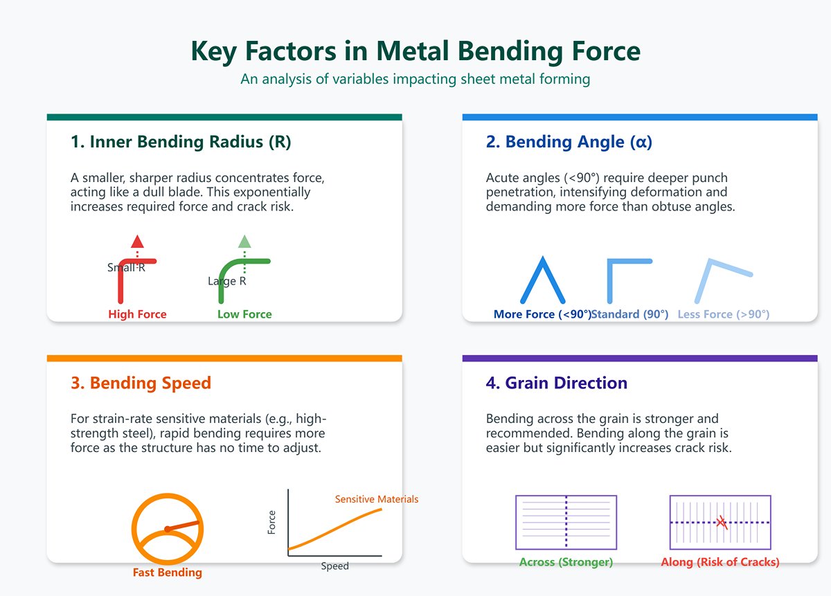
- Inner Bending Radius (R) – The standard formula assumes R ≈ V/6 to V/8. When aiming for a much smaller sharp radius, the punch tip exerts dramatically higher compression on the material—like cutting with a dull blade versus a sharp one. The smaller the radius, the greater the required bending force, potentially rising exponentially and increasing the risk of cracking.
- Bending Angle (α) – Standard formulas typically assume a 90° bend. For acute angles (<90°), the punch penetrates deeper into the die opening, intensifying deformation and requiring more force. Conversely, obtuse angles (>90°) demand less force.
- Bending Speed – For most common materials, speed has a minor effect. However, materials sensitive to strain rate—such as certain high-strength steels or titanium alloys—require greater force when bent quickly because their internal structure lacks time to reorganize during rapid deformation.
- Grain Direction – Rolling gives sheet metal a directional grain structure. Bending along the grain (parallel) is easier and requires less force but increases crack risk, while bending across the grain (perpendicular) yields stronger bends. Ideally, choose across-grain bending; otherwise, allocate extra force margin in calculations.
2.3 Common Misconceptions: Avoid the Pitfalls That Undermine Calculations
Theoretical perfection often breaks down in the roughness of real-world practice. Below are three of the most common cognitive traps that lead to “correct calculations, wrong results.”
- Trap 1: Treating Empirical Formulas as Physical Laws
Reality: The formulaP = (K × L × T² × UTS) / Vis an empirical model, derived from extensive experimental data fitting. It’s highly accurate under standard conditions but deviates under extreme cases—such as ultra-thin/thick sheets or unusual radii. Always regard the result as a precise reference, not absolute truth. Allow for a practical safety factor—typically around 20%. - Trap 2: Ignoring Material Batch Variations
Reality: Even within the same grade, tensile strength may vary by ±10% across batches or suppliers. Using handbook UTS values may misrepresent the actual sheet’s performance. For high-precision or borderline tonnage jobs, consult the Material Test Certificate (MTC) to obtain the true UTS value—a hallmark of professional accuracy. - Trap 3: Arbitrary Choice of V/T Ratio
Reality: The ratio between die opening (V) and sheet thickness (T) defines the essence of the bending process. A too-small ratio (V < 6T) skyrockets required force, risks damage to tools and machines, and causes cracks along the outer bend. Conversely, an excessively large ratio (V > 12T) reduces force but produces oversized radii and poor straightness. Always treat V/T as the primary process parameter, not just an adjustable number in the equation.
At this point, we’ve delved deep into the engine room of bending force calculation. You now understand not only the structure of the core formula but also the array of variables and hidden risks that affect its performance. With this comprehensive grasp of underlying principles, you’re ready for the next stage—transforming theory into precise, efficient, real-world application.
III. Practical Mastery—Four Steps to Accurate Bending Force Calculation
The value of theoretical depth lies in guiding practical precision. Having uncovered the fundamental logic behind bending force, we now arrive at the most rewarding phase: turning insight into action. This chapter presents a standardized, replicable four-step workflow that helps you distill clarity from complex workshop data and deliver a scientifically validated and reliable force estimate. This is more than just calculation—it’s a disciplined exercise in accuracy, safety, and efficiency.
3.1 Preparation Phase: Data Collection and Parameter Verification
Seventy percent of a successful calculation lies in preparation. Even a minor data flaw can be magnified through the formula, leading to dramatically inaccurate results. Approach this process as a pilot completing a pre-flight checklist—meticulous and uncompromising. Confirm the following parameters carefully:
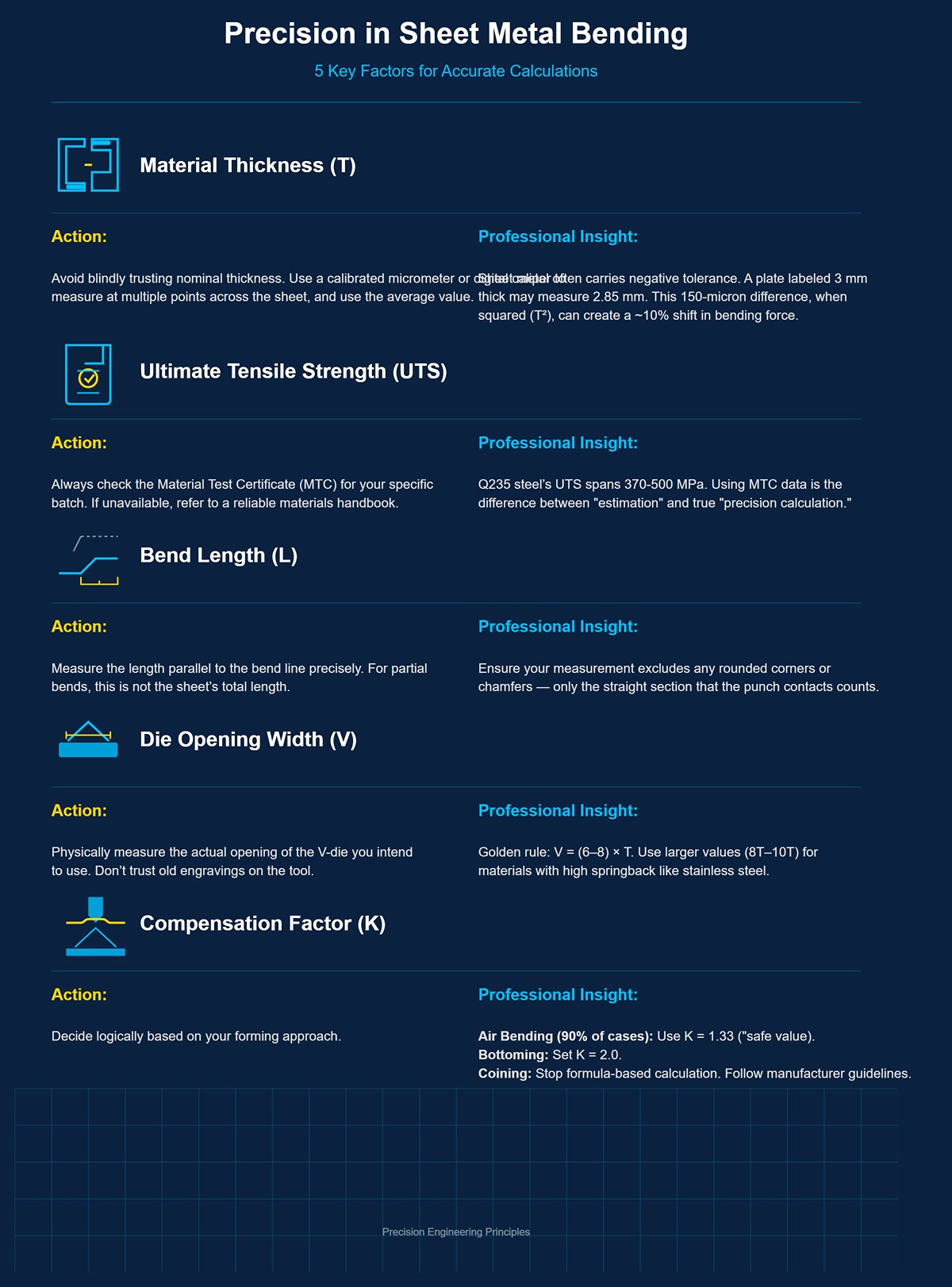
Material Thickness (T) — Precision over Nominal Values
- Action: Avoid blindly trusting nominal thickness. Use a calibrated micrometer or digital caliper to measure at multiple points across the sheet, and use the average value.
- Professional Insight: Sheet metal often carries negative tolerance. A plate labeled 3 mm thick may in reality measure only 2.85 mm. This 150-micron difference, when squared (T²), can create about a 10% shift in bending force. For critical calculations, that difference is decisive.
Ultimate Tensile Strength (UTS) — Finding the Material’s Identity Card
- Action: Your top priority should always be checking the Material Test Certificate (MTC) for your specific batch. It contains the most accurate UTS data. If unavailable, refer to a reliable materials handbook or the manufacturer’s technical datasheet.
- Professional Insight: Don’t rely on vague online ranges. For instance, Q235 steel’s UTS spans from 370 to 500 MPa—an enormous variation. Differences among steel mills and heat numbers can be substantial. Using MTC data marks your shift from “estimation” to true “precision calculation.”
Bend Length (L) — Measure the Effective Working Line
- Action: Measure the length parallel to the bend line precisely. For partial bends, this is not the sheet’s total length.
- Professional Insight: Make sure your measurement excludes any rounded corners or chamfers—only the straight section that the punch will contact counts.
Die Opening Width (V) — Confirm the Process Foundation
- Action: Physically measure the actual opening of the V-die you intend to use. Don’t trust old engravings on the tool, as wear can alter dimensions.
- Professional Insight: Die width selection is an art in itself. Adhere to the golden rule: V = (6–8) × T. For materials with high springback, such as stainless steel, lean toward larger values (8T–10T). For parts requiring tighter radii, smaller V values (around 6T) may be used—but be ready to handle the sharp increase in bending force.
Compensation Factor (K) — Define Your Bending Method
- Action: Decide logically based on your forming approach.
- In most cases (over 90%), Air Bending is used. Assign K = 1.33, a widely tested and slightly conservative safety value.
- For Bottoming, set K = 2.0.
- For Coining, stop formula-based calculation—this process requires extremely high forces and must strictly follow machine and tool manufacturer guidelines.
3.2 Calculation Phase: From Theoretical Value to Safe Working Value
With the data ready, it’s time to calculate. Keep in mind that the formula delivers an idealized, “laboratory-grade” theoretical value. We must apply a safety factor to convert it into a realistic engineering value suitable for workshop use.
Step 1: Calculate Theoretical Bending Force (P_theoretical)
Plug your verified parameters into the core formula: P (kN) = (K × L × T² × UTS) / V
- Example Calculation:
- Material: Q235 mild steel, thickness (T) = 3 mm
- UTS: From MTC, 420 MPa
- Bend length (L): 1000 mm
- Die opening (V): 8T = 8 × 3 = 24 mm
- Bending method: Air bending, K = 1.33
- P_theoretical = (1.33 × 1000 × 3² × 420) / 24 ≈ 209,475 N ≈ 209.5 kN
Step 2: Apply Safety Factor
Theoretical results are fragile—they don’t account for real-world fluctuations such as internal stress variation, die wear, or hydraulic oil temperature changes. The safety factor acts as armor against these uncertainties.
- Professional Recommendation:
- Standard Conditions (common carbon steel, mature process): Use a 20% safety factor.
- Demanding Conditions (high-strength steel, stainless steel, new material trials, or worn tooling): Increase to 30% or more.
Step 3: Determine Final Working Tonnage (P_working)
P_working = P_theoretical × (1 + Safety Factor)
P_working (Ton) ≈ P_working (kN) / 9.8 (approximately divide by 10 for quick estimation)
- Continuing the Example:
- Using standard conditions, Safety Factor = 20%.
- P_working (kN) = 209.5 × (1 + 0.20) = 251.4 kN
- P_working (Ton) ≈ 251.4 / 9.8 ≈ 25.7 tons
Core Insight: The theoretical value defines feasibility; the safety value ensures reliability.
3.3 Tool Recommendations: Leverage Tools for Greater Efficiency
In a fast-paced production setting, manual calculation yields precision but sacrifices speed. The following tools significantly improve efficiency—but remember: Tools extend your reach; they do not replace your judgment. Your understanding of the underlying principles remains the ultimate safeguard for validating the results these tools provide.
Online Bending Force Calculators:
- Advantages: Leading machine and tooling manufacturers such as TRUMPF, AMADA, and Bystronic all provide free online calculators. Simply input your parameters and get results instantly—ideal for quick estimation.
- Limitations: The built-in material data and K-factors are standardized and may not reflect the specific conditions of your production environment.
Self-Built Excel/Google Sheets Calculator:
- Advantages: Build it once, benefit for life. You can create a database tailored to your factory’s material system, integrating commonly used materials’ UTS values, various V-die dimensions, and your own safety factors. This is the most customizable and sustainable solution.
- Recommendation: Include unit conversion features (kN ↔ Ton, MPa ↔ PSI) in your sheet, and implement data validation checks to prevent input errors.
Built-in CNC System Programs:
- Advantages: Modern high-end press brakes feature CNC control systems with powerful built-in calculators. They connect directly to the machine’s database, offering force recommendations matched to current tooling and automatically monitoring pressure.
- Reminder: Regularly verify that the materials in the control system’s library match the actual materials you use. For any new material, cross-check the automatic calculation with manual computation as a safeguard.
3.4 Result Verification: Matching the Machine and Tooling
The computed 25.7 tons is not an isolated figure—it must be validated within the physical limitations of your machine and tooling.
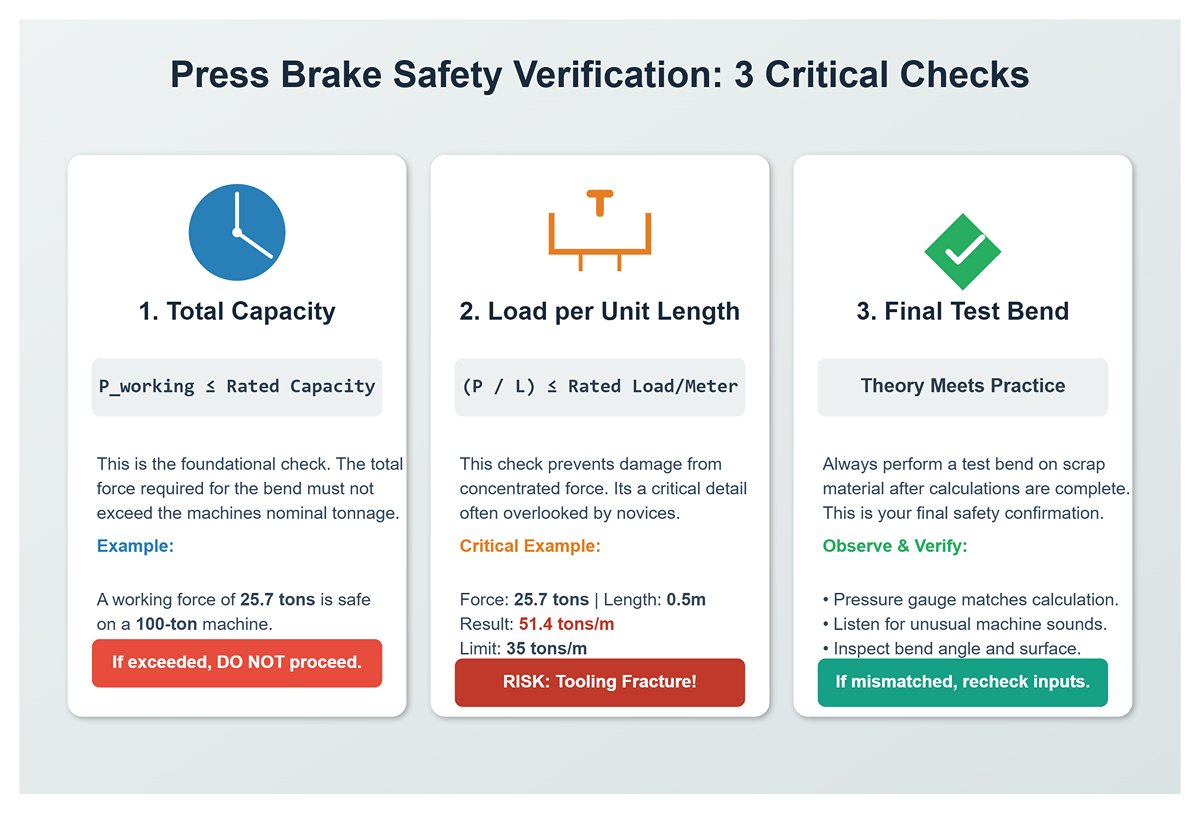
Verify the Machine’s Total Capacity:
- Check: P_working ≤ Machine’s Rated Press Capacity
- Explanation: This is the most basic verification. If your press brake is rated at 100 tons, then 25.7 tons is perfectly safe. If your computed force exceeds the nominal capacity, the operation must not proceed.
Verify the Allowable Tonnage per Unit Length (Tonnage per Meter):
- Check: (P_working / L) ≤ Machine/Tooling Rated Load per Meter
- This is the dividing line between professionals and novices! Many accidents occur because this factor is neglected. A 100-ton, 3-meter press brake can only handle a limited tonnage per meter—say, 35 tons/m.
- Example: Suppose you apply a 25.7-ton bending force on a plate only 0.5 meters long.
- Total tonnage of 25.7 tons < machine’s 100-ton rating — seems fine.
- But tonnage per meter = 25.7 / 0.5 = 51.4 tons/m.
- This exceeds the machine’s 35 tons/m rating! Forcing the operation could permanently deform or even fracture your tooling.
Final Verification: Test Bend
- Action: After all calculations and validations, perform an initial test bend using scrap material. Observe the pressure gauge, listen to machine sound, and inspect the bend angle and surface quality.
- Purpose: This is where theory meets practice. The actual pressure reading should closely match your calculated P_working. If not, recheck your inputs—especially material UTS and thickness.
By following this rigorous four-step process, you transform bending-force estimation from a rough guess into a precise, controllable engineering practice. Every figure in your calculation becomes a solid basis for safe, efficient, and high-quality production.
IV. Advanced Strategies: Evolving from Calculator to Optimizer
Mastering precise calculation gives you the key to professional craftsmanship. But true masters don’t stop at solving the equation—they seek optimization within real-world constraints, even accomplishing what seems impossible. In this chapter, we’ll guide you through the transformation from a precise calculator to a creative optimizer. This is no longer just about following the rules—it’s about applying them with insight and ingenuity.
4.1 The Art of Tonnage Optimization: Working Within Equipment Limits
Every sheet metal engineer has likely faced this challenge: the calculation calls for 120 tons of force, but your press brake’s rated capacity is only 100 tons. A novice might dismiss the job as impossible. An optimizer, however, sees a challenge—an opportunity to apply the “force-shifting method.” Here are three strategic levers you can employ:
Lever One: Optimize the Die Opening Width (V) — The Most Effective Way to Reduce Force
This should be your first and most powerful tool. Recall our core equation: P = (K × L × T² × UTS) / V. Bending force (P) is inversely proportional to the die opening (V). In other words, doubling the V value cuts the required force in half—assuming all else remains constant.
- Action Strategy:
- Reevaluate Your V/T Ratio: Are you still tied to the lower limit of
V = 6T? Gradually expand it to8T,10T, or even12Tif geometry allows. - Quantify It: Returning to our 120-ton challenge—suppose the current V is 48 mm (
V = 8Tfor a 6 mm sheet).
- To reduce 120 tons to under 100 tons (a 17% reduction), increase V by at least 17%. That means: 48 mm × 1.17 = 56.16 mm. Choose the nearest standard die, such as V58 or V60.
- Reevaluate Your V/T Ratio: Are you still tied to the lower limit of
- Trade-offs to Consider:
- Increased Bend Radius (R): A larger V inevitably results in a larger inside bend radius. Confirm that the enlarged radius remains within your design tolerance.
- Flange Length Limitation: Ensure the minimum flange length after bending is still greater than V/2—otherwise, the sheet may fall into the die and fail to form properly.
Core Insight: Never treat your press brake’s tonnage as an immovable wall—it’s more like a flowing river. By intelligently reshaping the channel (optimizing V), you can redirect the flow of force around obstacles.
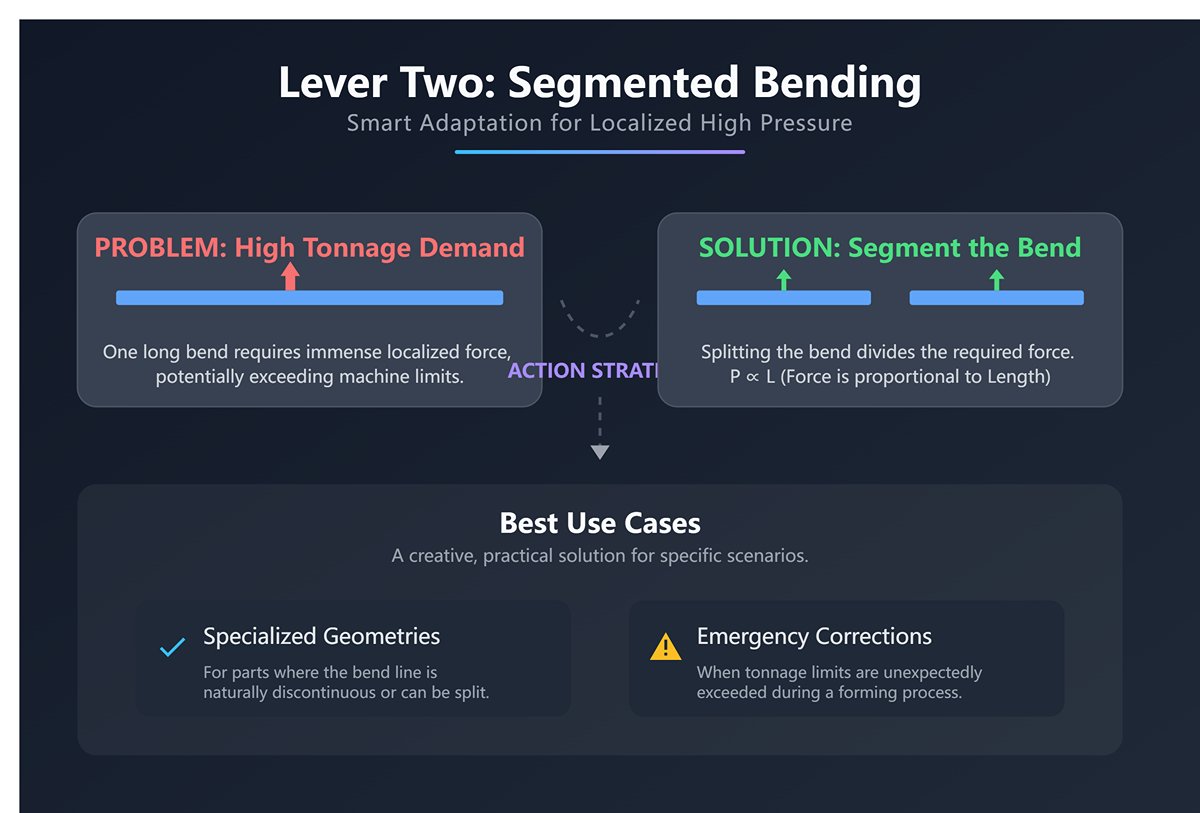
Lever Two: Segmented Bending — Smart Adaptation for Localized High Pressure
When dealing with short, thick sections that create localized high tonnage demands, consider altering your forming process.
- Action Strategy: If part geometry allows and the bend line is discontinuous, can you split one long bend into two or more shorter bends? Since
Pis proportional to the bend lengthL, halvingLhalves the required force. - Best Use Cases: This method isn’t for everyday situations, but for certain specialized geometries—or in emergency corrections where tonnage limits are exceeded—it offers a creative, practical solution.
Lever Three: Material Negotiation — Upstream Management Beyond the Workshop
When all process-based solutions have been exhausted, an outstanding engineer must possess the ability to trace issues back upstream.
- Action Strategy: Communicate with the design team or the customer to clarify the machining limits of the current material on existing equipment. Discuss whether it is possible to switch to a grade with slightly lower tensile strength or better ductility—without compromising the final product performance.
- Value Proposition: This approach demonstrates a deep understanding of the entire manufacturing chain, elevating the issue from a simple “execution challenge” to a “collaborative opportunity for systemic optimization.”
4.2 Guidelines for Special Materials and Complex Conditions
Standard formulas are tailored for ordinary carbon steel under ideal conditions. Once you step into the realm of specialty materials, it’s like switching from driving a sedan to handling a Formula One car—you must master an entirely new set of techniques.
1. Stainless Steel — Taming the ‘Spring Horse’
- Characteristics: High tensile strength, significant strain hardening, and substantial springback.
- Countermeasures:
- Force Adjustment: Take the calculated bending force for mild steel of the same thickness and multiply it by 1.5—a reliable starting estimate.
- V-Die Selection: Opt for
V = 8T ~ 10T. A larger V reduces required tonnage, provides a gentler bend, minimizes springback, and lowers the risk of cracking. - Angle Compensation: Stainless steel exhibits strong springback, requiring a greater overbend angle for correction. This demands high-precision angle control from your press brake.
- Characteristics: Soft texture, good ductility (with exceptions by grade), easily marred surfaces, and prone to cracking at small inside radii.
- Countermeasures:
- Force Reduction: Multiply the bending force for mild steel by 0.5 to 0.7, depending on alloy grade.
- Tooling Protection: Use nylon-lined V-dies or place a protective film between the sheet and die—standard practice for avoiding surface marks.
- Respect Grain Direction: Whenever possible, position the bend line perpendicular to the rolling direction to significantly reduce the risk of outer-surface cracking.
- Radius Tolerance: Avoid designs with sharp inner radii. Aluminum typically requires a bend radius larger than the material thickness (R ≥ T); otherwise, cracking risk increases sharply.
2. High-Strength Steel (e.g., Hardox) — Battling the ‘Steel Beast’
- Characteristics: Exceptionally high tensile strength, severe springback, and minimal ductility.
- Countermeasures:
- Force Surge: Bending force may reach three to four times, or even more, than that required for mild steel of equal thickness. Always base calculations on verified UTS data from the material supplier and include a substantial safety margin (≥30%).
- V-Die Expansion:
V = 12Tis only a starting point;16Tor even20Tare common. This adjustment is vital to prevent overload and mold failure. - Tool and Machine Rigidity: Use specially designed, high-strength dies with generous radii. Your press brake must also have superior structural rigidity and deflection compensation—any compromise could result in catastrophic failure.
3. Complex Bending Scenarios: Beyond the Basic V-Bend
- Hemming: A two-stage process—start with a sharp pre-bend of about 30°, then flatten it using a compression die. The flattening force is enormous and cannot be computed with standard formulas; always refer to the tooling manufacturer’s tonnage charts.
- U-Bend or Offset Bending: These involve multiple bends and complex stress distributions, demanding significantly more tonnage than a single 90° bend. The most reliable data source is the technical manual from your die supplier.
4.3 Common Problems Diagnostics and Troubleshooting
When theoretical calculations are correct but real-world outcomes deviate, you’ve entered the advanced diagnostic phase. Like an experienced doctor, you must infer the root cause from the symptoms.
| Symptom | Potential Causes | Diagnosis & Solution |
|---|---|---|
| Actual tonnage significantly higher than calculated | 1. Material mismatch: actual UTS much higher than specified. 2. Worn V-die: actual opening smaller than nominal. 3. Punch radius too small: sharp tip causes penetration effect. 4. Sheet thickness at upper tolerance limit. | 1. Verify using MTC or perform mechanical testing. 2. Measure V-die opening and replace worn tooling. 3. Use a punch with larger radius. 4. Re-measure sheet thickness and update parameters. |
| Unstable bend angle, excessive springback | 1. Batch variation: material properties fluctuate. 2. Press deflection: “canoe effect” causing center sag. 3. Insufficient tonnage: pressure below material yielding threshold. | 1. Conduct first-piece testing for each batch and adjust compensation. 2. Activate or fine-tune press crowning system. 3. Recalculate tonnage and review chosen V value. |
| Cracks on outer bend surface | 1. V/T ratio too low: bend radius below material limit. 2. Bending along grain direction. 3. Burr located on tension side, creating stress concentration. | 1. Increase V value—most effective fix. 2. Rotate part 90° for cross-grain bending. 3. Deburr edges or place burr on inner (compression) side. |
| Visible surface indentation | 1. Excess unit pressure: tonnage concentrated on narrow contact area. 2. Sharp shoulders on V-die: worn or improper design. 3. Surface contamination: oxide scale or debris present. | 1. Choose larger V value to distribute pressure. 2. Replace V-die with smoother or polished shoulders. 3. Clean sheet surface beforehand or apply protective film. |
After completing this chapter, you are no longer merely entering parameters—you’ve become a strategist, a diagnostician, and a process-optimization master who thrives under constraints. Your press brake is no longer a cold machine, but an extension of your craft in the art of precision forming.
V. Conclusion
In short, mastering press brake bending force transforms fabrication from an art reliant on experience into a science driven by data. By understanding that force is a dynamic result of material, thickness, and tooling choices, you move from simply operating a machine to commanding a predictable process.
This knowledge is the key to ensuring safety, achieving precision, eliminating waste, and optimizing every facet of your production. For a deeper technical overview, you can explore our detailed Brochures that cover specifications, tooling options, and application examples.
Ready to turn theory into profit? The experts at ADH can help you apply this knowledge to achieve tangible gains in efficiency and quality. We will help you analyze your applications and refine your processes to ensure every bend is perfect. You can contact us today for a consultation and turn your bending force knowledge into a decisive competitive advantage.


