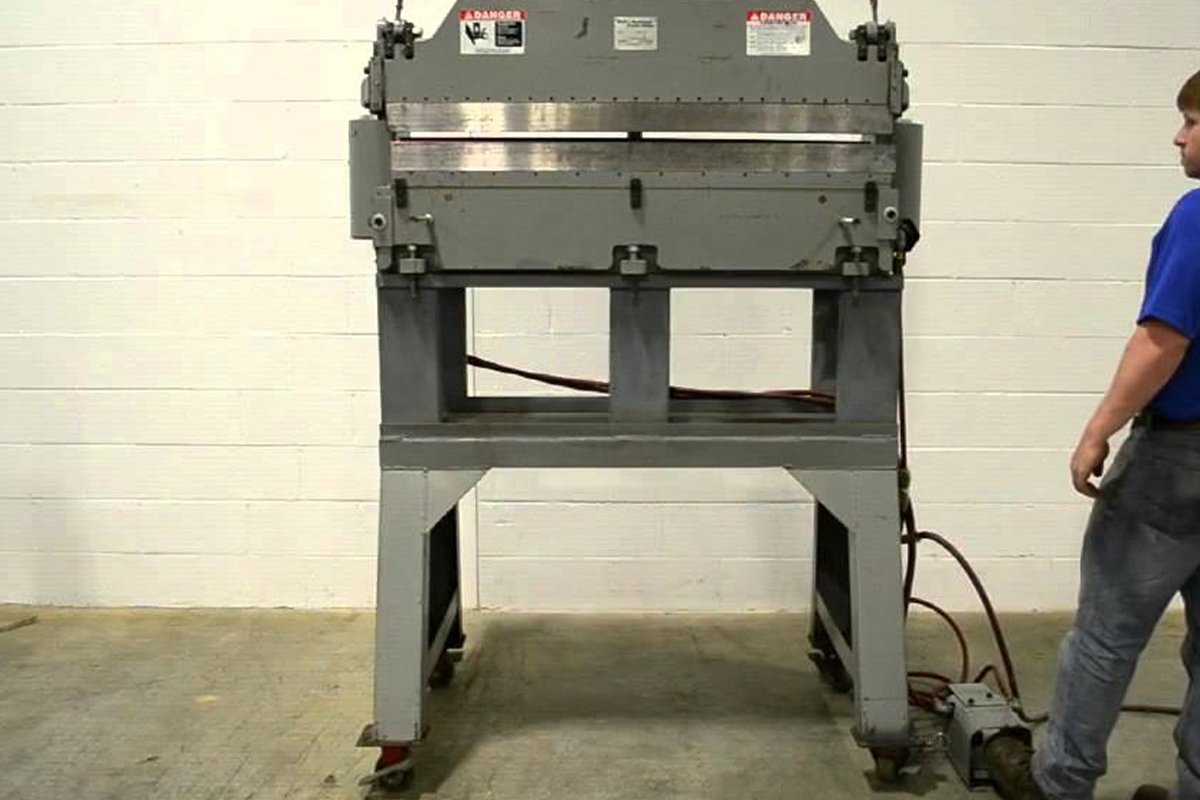
Understanding how pneumatic press brakes work is the first step toward mastering precision and speed in lightweight metal fabrication. These machines translate the simple power of compressed air into the force needed to bend sheet metal with remarkable efficiency. Unlike their larger hydraulic counterparts, pneumatic brakes excel in high-volume, high-accuracy applications where control is paramount.
This guide will take you from the fundamental principles of air pressure and force to the advanced strategies of operational mastery. We will equip you with the practical knowledge to transform your skills, turning you from a capable user into a true expert of the machine.
I. Fundamental Understanding: Why Pneumatic Press Brakes Are the “Invisible Champions” of Lightweight Precision Manufacturing
1.1 Defining the Core Value: More Than Just Air Power—A Synonym for Speed and Precision
It would be an oversimplification to describe a pneumatic press brake as merely “air-driven machinery.” Its true value lies in converting clean, highly responsive compressed air into precisely controlled mechanical force, achieving exceptional performance in two critical dimensions: speed and precision.
- Lightning Speed: The Physical Nature of Air
Unlike viscous hydraulic oil, air’s fluidity and compressibility give pneumatic systems an unmatched response rate. The time lag between command execution and ram movement is minimal, allowing dramatically shorter cycle times—ideal for high-volume bending of small components such as electronic housings or precision instrument parts. Think of it as a sprinter who thrives on rapid starts and stops, pushing production efficiency to new heights. - Micron-Level Precision: Gentle Yet Firm Force Control
Though not as powerful in absolute tonnage as hydraulic systems, pneumatic press brakes excel in the fineness of force delivery. Air pressure adjustment is both linear and highly sensitive, enabling precise control over the pressure applied to thin sheet materials. This minimizes risks like overpressure damage, surface indentations, or inconsistent bending angles. For applications that demand flawless surfaces and consistent bends—such as instrument panels or high-end enclosures—this refined control is the cornerstone of superior quality. - The Overlooked “Invisible” Advantages:
- Energy Efficiency: A pneumatic system consumes energy only during active operation. In standby mode, it draws virtually no power—unlike hydraulic systems that must keep pumps running continuously—making it remarkably energy-efficient.
- Environmental Friendliness: Powered by clean compressed air, it eliminates the risk of oil leaks and the related cleanup costs. This makes it an ideal choice for hygienic manufacturing environments such as food processing, medical devices, and cleanrooms.
- Simplified Maintenance: With a straightforward structure free from complex oil circuits and pump stations, the system greatly reduces maintenance workload and costs while improving reliability.
1.2 Identifying Application Scenarios: When Should You Choose a Pneumatic Press Brake Without Hesitation?
Once you grasp its core value, making the right choice becomes effortless. When your production requirements align with one or more of the following characteristics, a pneumatic press brake isn’t just suitable—it may be the optimal solution:
- Thin Sheet Processing Focus: Ideal when your primary work involves materials such as carbon steel, stainless steel, or aluminum sheets under 3mm thick.
- Pursuit of Extreme Efficiency: Perfect for high-output operations requiring repetitive bending of small components, where short cycle times directly translate into increased throughput.
- High-Precision Requirements: Essential for industries demanding consistent bending angles and flawless surface finish, including precision enclosures, instrumentation, and telecommunications equipment.
- Clean Manufacturing Environments: Best for facilities with strict cleanliness standards, such as those in food machinery, medical device production, or pharmaceutical equipment.
- Cost and Maintenance Sensitivity: A smart choice for small to medium enterprises seeking high-quality fabrication with lower initial investment and minimal long-term upkeep.
In short, the pneumatic press brake is expertly engineered to meet the modern manufacturing demands of being “light, fast, precise, and clean.”
1.3 Key Differences: Pneumatic vs. Hydraulic vs. Mechanical Press Brakes—A Single Table Overview
To simplify your equipment selection process, here’s a comprehensive comparison across key performance dimensions. This table serves as a practical guide for informed decision-making.
| Feature | Pneumatic Press Brake | Hydraulic Press Brake | Mechanical Press Brake |
|---|---|---|---|
| Power Source | Compressed Air | Hydraulic Oil | Flywheel with Clutch/Brake |
| Tonnage Range | Small (typically < 100 tons) | Wide (up to several thousand tons) | Medium to Large |
| Speed | Fastest (shortest cycle time) | Adjustable, but slower to start/return | Fast, but generally fixed |
| Accuracy & Control | High (precise pressure control for thin sheets) | Very High (programmable pressure and stroke) | Lower (relies on mechanical stops, less flexibility) |
| Initial Cost | Low | High | Moderate |
| Maintenance Cost | Lowest (simple design, no oil circuit issues) | Higher (oil, seals, pumps, valves) | Moderate (clutch/brake wear) |
| Energy Consumption | Low (on-demand operation) | High (pump runs continuously) | Moderate |
| Environmental Impact | Excellent (clean, low noise) | Risk of oil leaks, relatively noisy | Highest noise levels |
| Typical Applications | Thin sheets, small parts, large volume, clean environments | All sheet thicknesses and complex shapes | Simple, high-volume medium-thickness parts |
| Core Strengths | Speed, cleanliness, low cost, high efficiency | Tonnage capacity, versatility, precision, maturity | Robust build, fast operation |
| Core Limitations | Limited tonnage, unsuitable for thick sheets | High cost, high energy use, slower cycle | Lower safety, higher noise, reduced accuracy/flexibility |
II. Deep Dive into the Principles: How Compressed Air Is Transformed into Micron-Level Bending Precision
The precision of a pneumatic press brake doesn’t stem from the sheer power of a single component. Instead, it emerges from the seamless orchestration of the entire system—each part interacting like gears in a finely tuned timepiece.
By mastering the compressibility and instantaneous response of air, it performs a breathtaking act of converting invisible pressure into visible, microscopic deformation. This chapter will guide you through that transformation, revealing the physics and engineering finesse behind what appears to be a deceptively simple process.
2.1 The Journey of Force: A Step-by-Step Overview from Air Compressor to Perfect Bend
Imagine compressed air as a perfectly guided arrow of energy—its journey, from creation to impact, follows a meticulously controlled sequence, ensuring every motion results in precision-perfect bending.
- Energy Generation & Storage: All power begins with the air compressor—the beating heart of the machine. It draws in the ever-present ambient air, compresses it to dramatically increase its energy density, and safely stores this potential energy in the air reservoir under high pressure. This creates a stable, readily available power reserve for every subsequent operation.
- Command Activation: When the operator steps on the foot pedal or presses the start button on the CNC control panel, a small electrical signal is sent on its way. This signal acts like a military command, instantly reaching the pneumatic system’s nerve center—the solenoid valve.
- Regulated Release: The moment the solenoid valve receives the signal, it opens the designated air passage within milliseconds. What’s released isn’t raw, uncontrolled high pressure, but air that has been carefully tamed by the pressure regulator. Based on preset parameters, the regulator reduces the reservoir’s high-pressure air (e.g., 120 PSI) down to the precise working pressure required for the bending task (e.g., 75 PSI), ensuring the force is perfectly calibrated from the start.
- Linear Conversion (Pressure to Force): The regulated compressed air is directed into the sealed chamber of the pneumatic cylinder. Here, the transformation occurs: air exerts uniform pressure on the effective surface area of the piston, and according to the fundamental physics equation Force = Pressure × Area, the invisible pressure is converted into a powerful, steady, and precisely directed linear thrust.
- Force Transmission: The piston’s motion is transferred via the piston rod to the rigidly connected ram, which begins moving vertically downward. The ram is the key moving component that holds the upper die (punch), and its smoothness and vertical accuracy directly determine the quality of the final bend.
- Final Forming: The ram drives the punch downward with controlled speed and precision, pressing the metal sheet mounted on the lower die into shape. Under the combined action of the upper and lower tooling, the metal’s internal lattice shifts, causing plastic deformation, and the sheet is bent to the exact predetermined angle and form.
- Rapid Reset: As soon as the bending command is complete, the control system reverses the solenoid valve’s state, cutting off the air supply and opening the exhaust port. The quick exhaust valve rapidly vents the compressed air from the cylinder into the atmosphere, instantly releasing the pressure. Under the force of internal springs or reverse air pressure, the ram and punch swiftly return to their initial position, ending a flawless cycle and awaiting the next command.
2.2 Deconstructing the Core Components: How Each Part Plays a Critical Role in Precision Coordination
If the process above is a masterful symphony, then the following core components are the indispensable musicians, each playing their part in perfect harmony to produce precision.
| Component | Key Function | Role in Precision Control |
|---|---|---|
| Pressure Regulator | Precisely adjusts unstable high pressure from the reservoir to the stable working pressure required for the task. | The source of accuracy—it’s the first checkpoint determining the force applied to the workpiece, directly affecting bend angle and material deformation. |
| Solenoid Valve | Serves as the interface between electrical control and pneumatic execution, responsible for opening or closing the air path quickly and on time. | Guarantees response speed—its switching rate dictates system reaction time, essential for high-speed, repetitive bending. |
| Flow Control Valve | Regulates the air flow entering or exiting the cylinder, thereby controlling the motion speed of the piston (ram). | Crucial for process control—by managing bending speed, it reduces springback, minimizes fracture risk, and optimizes surface finish. |
| Cylinder & Piston | Convert the regulated air pressure into usable mechanical thrust via the piston’s effective area. | The force executors—the cylinder’s diameter and sealing quality directly influence output stability and efficiency. |
| CNC Controller | The control brain—integrates programming control for pressure, ram stroke (Y-axis), and backgauge position (X-axis). | The heart of micron-level precision—with closed-loop control and sensor feedback, it compensates for variables to achieve highly repeatable accuracy. |
| Linear Scale/Encoder | Mounted on either side of the ram to continuously monitor and feed back its exact position to the CNC system, with micron-level accuracy. | The eyes of position feedback—ensures ram descent depth (and thus bend angle) is precisely measured and controlled, foundational for high-accuracy angle control. |
2.3 Physics Explained: Converting PSI to Tonnage—The Formula Behind Pressure and Bending Force
Turning the abstract unit of pressure (PSI) into the tangible bending force (tons) relies on a straightforward yet powerful physics principle. Mastering it reveals the essence of a pneumatic press brake’s power.
The core formula is:
F = P x A
Where:
- F is the total thrust generated by the cylinder (Force), typically measured in pounds (lbs) or newtons (N).
- P is the effective air pressure applied to the piston (Pressure), measured in pounds per square inch (PSI) or pascals (Pa).
- A is the piston’s effective area (Area), measured in square inches (in²) or square meters (m²). The calculation formula is A = pi x (D/2)^2, where D is the cylinder diameter.
Converting Thrust to Tonnage: In the US customary system, 1 short ton equals 2,000 pounds. Dividing the calculated total thrust (F, in pounds) by 2,000 gives the press brake’s theoretical tonnage.
Example Calculation: Suppose a pneumatic press brake uses a cylinder with a 10-inch diameter and a working pressure set to 90 PSI.
Calculate the piston area (A):
Determine total force (F):
Convert to tonnage:
This straightforward calculation reveals an elegant piece of engineering insight: by designing a sufficiently large piston area, even moderate air pressure can be multiplied into a force powerful enough to bend steel. This is the essence of how pneumatic systems achieve great strength from humble beginnings.
2.4 Dispelling a Core Misconception: Why “Maximum Air Pressure” ≠ “Best Bending Result”
This is a critical practical question and a key distinction between beginners and seasoned engineers. Cranking up the air pressure to its maximum rarely improves performance—it’s often the very cause of defects and equipment damage. The reasons fall into three fundamental categories:
- The nature of different bending methods: Sheet metal bending can be performed in three ways—Air Bending, Bottoming, and Coining.
- Air Bending is the most common method and requires the least force. The punch presses the sheet into the die without fully touching the die’s bottom; the bend angle depends on the punch’s penetration depth. Applying excessive pressure here causes over-bending and scrap parts.
- Bottoming and Coining demand much higher forces, as they rely on forcing the material to conform exactly to the die shape or to “coin” the metal surface, eliminating springback.
Key misconception: Using coining-level pressure for an air-bending process is like calibrating a watch with a sledgehammer—the outcome will inevitably be catastrophic.
- The inevitability of material springback: All metals naturally attempt to return slightly toward their original shape after plastic deformation—a phenomenon known as springback. The art of precision bending lies in applying just enough force to intentionally “over-bend” by a calculated amount, so the final angle aligns perfectly after springback. Excessive pressure disrupts the internal stress balance, leading to unpredictable or uncorrectable results.
- Material strength limits: Every metal has specific tensile strength and minimum bend radius parameters. Exceeding these thresholds can cause microcracks on the outer bend or wrinkling on the inner surface—both detrimental to the part’s strength and appearance. For thin sheets or brittle materials, a gentle but accurate force is far more valuable than brute strength.
True experts don’t chase “maximum pressure.” Instead, they fine-tune a custom pressure and speed curve tailored to each material, thickness, angle, and bending technique through the CNC system. This marks the leap from merely operating a machine to mastering it—and is the key to achieving micron-level precision with pneumatic press brakes.
III. Mastery in Practice: From Novice Operation to Expert-Level Control
Theory provides the map, but practice is the only road to mastery. To excel with a pneumatic press brake is to evolve from a passive operator into a proactive steward of quality. This is not only about efficiency—it embodies the craftsmanship behind every finished part.
In this chapter, we’ll move beyond theory with a refined, field-tested methodology that transforms conceptual understanding into impeccable precision on the production floor.
3.1 Pre-Startup Checklist: Five Key Steps to Prevent 90% of Operational Errors
Discipline is the foundation of excellence. More than 90% of unplanned shutdowns and operating mistakes stem not from complex technical issues but from neglecting basic procedures. Turn the following five steps into muscle memory, and you’ll build the strongest barrier against accidents and inefficiency.
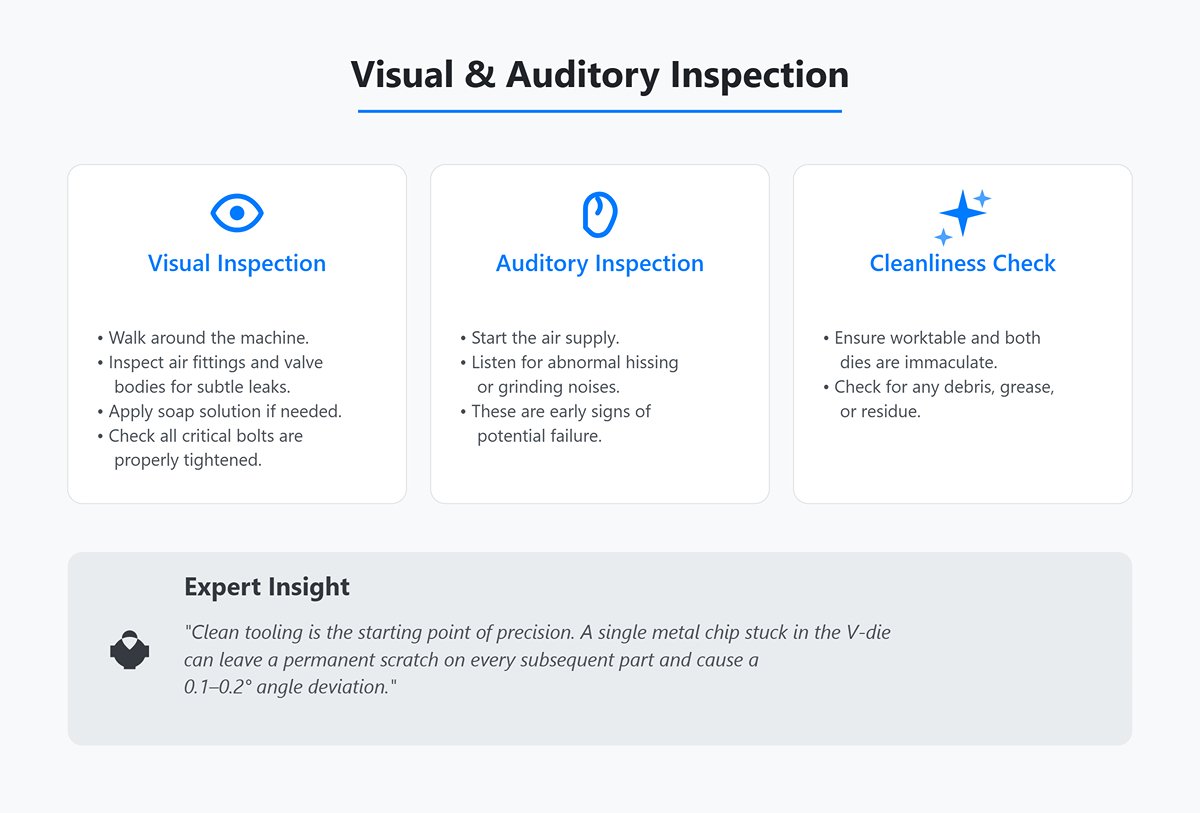
Visual & Auditory Inspection
- Checklist: Walk around the machine and visually inspect air fittings and valve bodies for subtle leaks (apply soap solution if needed), and check that all critical bolts are properly tightened. Listen for abnormal hissing or grinding noises after starting the air supply—these are early signs of potential failure. Finally, ensure the worktable and both dies are immaculate, free of debris, grease, or residue.
- Expert insight: Clean tooling is the starting point of precision. A single metal chip stuck in the V-die can leave a permanent scratch on every subsequent part and cause a 0.1–0.2° angle deviation.
Safety System Verification
- Checklist: This is a non-negotiable step. Systematically press every emergency stop button to confirm they instantly cut power. Test the light curtain safety system—ensure any object (such as a certified test rod) entering the protected zone during ram descent triggers an immediate stop and return. Check the foot pedal, making sure its three-stage control (“rapid down–working stroke–return”) functions responsively and without sticking.
- Expert insight: Do not test the light curtain casually with your hand. Use an approved standard test rod, approaching from different angles and speeds to simulate real intrusion scenarios. This rigorous test ensures the curtain’s responsiveness and full coverage, leaving no safety blind spots.
Air Supply & Lubrication System Check
- Checklist: Confirm the main air pressure gauge reads within the manufacturer’s specified range (typically 0.6–0.8 MPa). Inspect the pneumatic FRL unit: ensure the filter cup is free of water or contaminants (drain if necessary), the regulator maintains steady output pressure, and the lubricator oil level and drip rate are within range.
- Expert insight: More oil is not better. Excessive mist can contaminate workpieces and the workspace, while too little accelerates wear in cylinders and valves. Follow the manual strictly—set the oil drip rate to the golden range of 1–3 drops per minute.
Backgauge Homing & Calibration
- Inspection Key Points: After powering up, always perform the Homing Procedure for all axes—especially the X and R axes of the backgauge. This step establishes an absolute zero point for the machine’s coordinate system. Next, use a calibrated caliper or gauge block to measure the actual distance between the front edge of the back finger and the center of the lower die’s V-groove. Compare this measurement with the CNC display value to verify that positioning accuracy remains within the specified tolerance.
- Master Insight: Fluctuations in ambient temperature can cause the leadscrew to expand or contract, resulting in micrometer-level positional drift of the backgauge. Before conducting ultra-precision operations, allow the machine to warm up and run for 15–20 minutes prior to calibration. This ensures more stable and accurate readings.
Tooling Alignment & Condition Check
- Inspection Key Points: Carefully inspect the punch tip and the shoulders of the lower die (V-groove) for chipping, wear, or dents. After installing or replacing the tooling, always perform a centering procedure. Switch to “jog” mode and slowly lower the ram until the punch tip gently enters the lower die’s V-groove. Use both visual inspection and tactile feedback to confirm that the two are perfectly aligned along their full working length.
- Master Insight: Misaligned tooling is the primary cause of inconsistent bend angles and uneven pressure marks. A professional trick is to place a sheet of white paper between the upper and lower dies, apply light pressure, and examine the imprint. A perfectly centered, uniform, and crisp line is the ultimate confirmation of proper alignment.
3.2 The Art of Parameter Calibration: Mastering the “Triad of Perfect Bending”
A flawless bend is the result of the dynamic balance among Force, Depth, and Position—the three essential pillars of bending mastery. Once you command this “triad,” you hold the key to elevating results from merely acceptable to truly exceptional.
Force Setting: Gentle Yet Firm
- Core Principle: Always apply the minimum force necessary to complete the job. Overloading is one of the most common mistakes among beginners. Based on material type, thickness, bend length, and V-die width, use a bending force chart or the machine’s built-in software to determine the theoretical tonnage.
- Calibration Technique: In air bending, the goal is to push the material just beyond its yield point to achieve plastic deformation—not to forcibly press it into the die bottom. Setting the actual pressure to 105%–115% of the theoretical value is typically an ideal starting point. When working with unfamiliar materials, begin with a noticeably lower pressure, perform a test bend, and gradually increase it until achieving a crisp bend line without excessive marking. Remember: accurate force control is the first step to managing springback and the key to prolonging die life.
Depth Adjustment: Dancing with Springback
- Core Principle: In a CNC press brake, the final bend angle is determined directly by the depth of the punch’s entry (Y-axis position) into the lower die.
- Calibration Technique: This is the frontline in compensating for material springback—a natural property of metal that can never be eliminated, only controlled. For instance, to achieve a precise 90° finished angle, you may need to program the machine to bend to 88°, intentionally “overbending” by 2°. There is no universal formula for this compensation; it varies with material batch, hardness, rolling direction, and even press speed. True professionals perform one or two test bends, measure the resulting angle with a protractor, and then fine-tune the Y-axis setting accordingly.
- Correction Rule: If the test bend yields 91° (1° under-bent), increase the Y-axis penetration; if it produces 89° (1° over-bent), decrease it. After a few fine adjustments, you’ll pinpoint the optimal parameters for the current material batch.
Backgauge Fine-tuning: Perfecting Human–Machine Harmony
- Core Principle: The backgauge (X-axis) defines the dimensional accuracy of the bend flange.
- Calibration Technique: When consistent dimensional deviations of 0.1–0.2 mm occur, resist the urge to immediately correct the backgauge position. First, examine and standardize your operating technique. Are you consistently bringing the workpiece into contact with the back fingers smoothly and with uniform pressure each time? Do you “touch” or “hit” the stops? The latter can cause material rebound and slight deformation of the finger stoppers, leading to measurement errors. Once you’ve ensured absolute consistency in your handling method, then proceed to apply micron-level compensation adjustments to the backgauge coordinates. Remember: the ultimate precision of the machine is often determined by the operator’s consistency.
3.3 The Four-Step Standard Bending Cycle: Achieving Consistent, Efficient Repetition
For mass production, internalizing a rhythmic, standardized cycle for each bending operation is key to achieving both efficiency and quality. This four-step method provides a professional, safe, and repeatable operational rhythm.
Positioning
- Action Essentials: Hold the sheet firmly and steadily with both hands, guiding it quickly but smoothly toward the backgauge. Ensure that its edge makes even and secure contact with all relevant stops, and feel for clear tactile feedback at the moment of contact. Before pressing the foot pedal, make sure both hands are completely outside the die’s danger zone.
- Key Point: The motion should end in a “touch,” not a “hit.” Avoiding impact-induced rebound against the backgauge is the foundation of dimensional consistency.
Initiation & Approach
- Action Essentials: Gently press the first stage of the foot pedal—the ram will quickly descend to the “transition point” (typically about 10 mm above the sheet surface), where the machine automatically slows down. At this fleeting moment, release the pedal and perform a final visual check: is the workpiece properly positioned, and are your hands safely clear?
- Key Point: This deliberate “pause and confirm” habit is the final—and most crucial—safeguard against finger injuries and scrap caused by misalignment.
Bending
- Action Essentials: Press and hold the foot pedal again to engage bending at the preset working speed. Keep your stance stable and your focus fixed on the bending area, watching closely for any irregularities.
- Key Point: Never attempt to manually “correct” or “steady” the workpiece while the ram is in motion. This is extremely dangerous and offers no benefit to forming quality. Trust the parameters you’ve so carefully set.
Return & Removal
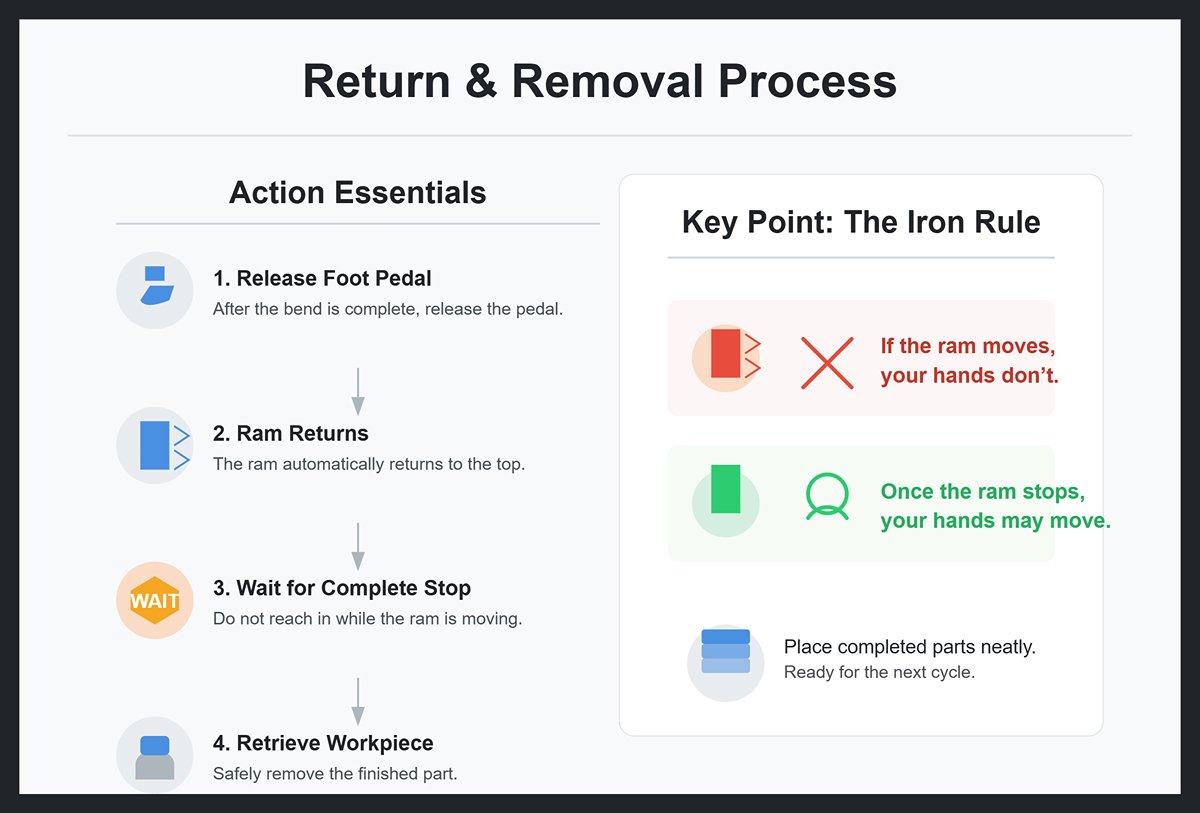
- Action Essentials: After the bend is complete, release the foot pedal—the ram will automatically return rapidly to the top dead point. Always wait until the ram has come to a complete stop before reaching in to retrieve the finished workpiece.
- Key Point: Adhere to the iron rule: “If the ram moves, your hands don’t; once the ram stops, your hands may move.” Place completed parts neatly in the designated area, readying yourself for another flawless cycle.
IV. The Path to Mastery: Maintenance, Troubleshooting, and Intelligent Upgrades
4.1 Preventive Maintenance Program: Maximizing Equipment Lifespan and Uptime
Excellence stems from consistent dedication. Preventive maintenance is not a time-consuming burden—it is the most efficient investment in combating wear, preserving accuracy, and preventing unexpected downtime. It is a disciplined conversation with your machine, designed to keep it performing at its absolute peak.
- Daily: Operator-Level Basic Maintenance — The Foundation of Discipline
- Pristine Cleanliness: Use non‑abrasive cloths and low‑pressure compressed air to thoroughly clean the worktable, upper and lower dies, backgauge, and encoder scale surfaces. This is where micron‑level precision begins.
- Listen to the Air System: After starting up, listen carefully around air hoses and valve bodies for subtle “hissing” signs of leakage. Drain condensation from the air filter (the first component of the pneumatic triad).
- Safety Red‑Line Test: Always test the emergency stop button, light curtain protection, and foot pedal functions first when powering up. Safety is the foundation of all efficiency.
- Lubrication Inspection: Visually check that the automatic lubrication system (if installed) maintains oil levels above the safety line and confirm that lubricant is reaching all critical points.
Master’s Insight: Never use solvents or rough fabrics when cleaning the encoder scale. Wipe gently in one direction with a lens cloth moistened with anhydrous ethanol. Even a tiny scratch can introduce a permanent, difficult‑to‑trace positional error within the CNC system.
- Weekly: Enhanced Inspection and Tightening — Prevent Minor Issues Before They Grow
- Clean the “Lungs” of the Air Source: Check the air filter element of the source treatment unit. If discolored or the pressure‑drop indicator shows an alarm, clean or replace it immediately. Clean air ensures long service life for pneumatic components.
- Critical Bolt Torque Check: Inspect and torque key bolts at the die clamps, backgauge transmission components, and motor base using a torque wrench. Vibration is the invisible killer of machine accuracy.
- Reforming the “Oil Film” of Guide Rails: Thoroughly clean the linear guide rails of the ram and backgauge, then apply the specified grade of grease to ensure an even, continuous lubrication film.
- Monthly: Precision Calibration and Deep Diagnostics — Reestablishing the Baseline
- Ram Parallelism Calibration: Using two dial indicators with at least 0.01 mm accuracy, measure at both ends of the worktable to verify parallelism of the ram throughout its stroke. This is the key to consistent bend angles across the entire part.
- Backgauge Accuracy Verification: With calibrated gauge blocks or specialized checking tools, systematically verify the actual positions of the backgauge at multiple common reference points and correct any deviations found in the system readout.
- Cylinder Condition Assessment: In manual mode, let the cylinder travel its full stroke slowly under no‑load conditions. Observe its smoothness and listen for internal noises or abnormal exhaust sounds.
- Annually: Professional Comprehensive Diagnostics — Renewal and Evolution
- Renew the “Vascular System” of Pneumatics: Have a qualified engineer inspect and replace any hoses showing signs of aging or hardening, and replace internal seals of all key solenoid valves. This preventive action averts over 90% of air‑related sudden failures.
- Evaluate the “Skeleton” for Mechanical Wear: Perform a full inspection of guide rails, ball screws, and support bearings for clearances indicating wear. Mechanical degradation is inevitable; the key is predictable replacement before tolerances are exceeded.
- Backup the CNC System—the “Soul” of Precision: Create complete backups of all machine parameters, lead‑screw compensation data, PLC programs, and user machining programs. Store them securely offsite—your ultimate safeguard against data loss.
4.2 Rapid Troubleshooting Guide: Thinking Like a Senior Engineer
| Common Fault | Logical Diagnostic Path (in Priority Order) | Recommended Solution |
|---|---|---|
| Inconsistent or Inaccurate Bending Angle | 1. Operational Variables: Are operators feeding the material in exactly the same way each time? Is the workpiece consistently and firmly pressed against all backgauge fingers? 2. Material Variables: Has a new batch of sheet metal been introduced? Use a caliper to verify that its actual thickness matches the program setting. 3. Feedback System: Is the linear scale surface clean and free of oil or scratches? Is the reading head firmly secured? 4. Execution System: Are the punch and die contact surfaces worn? Has the slider-to-table parallelism drifted out of tolerance? | 1. Standardize Operations: Develop and follow a consistent feeding SOP—aim for light, steady, and precise motions. 2. Trial Bending Calibration: For each new batch, perform 1–2 test bends to quickly adjust the angle compensation value. 3. Clean and Tighten: Clean the linear scale as specified and inspect all fasteners for tightness. 4. Inspect and Recalibrate: Check for die wear; replace or reposition as needed. Recalibrate slider parallelism. |
| No Pressure / Insufficient Tonnage | 1. Power Source: Is the air compressor output pressure normal? Are the main air valves fully open? 2. Parameter Settings: Are the pressure or tonnage parameters in the program correctly set? 3. Air Leak Detection: Use soapy water or an ultrasonic detector to check all lines and fittings from the regulator to the cylinder. 4. Core Valves: When actuated, do the indicator lights on the solenoid or proportional valves illuminate? Is there a normal magnetic pull sound from the coil? 5. Power Core: Are the piston seals in the cylinder worn and causing internal leakage? (Typically seen as slow pressure buildup accompanied by continuous exhaust noise.) | 1. Ensure Air Supply: Adjust compressor pressure and verify all air valves are open. 2. Verify Parameters: Check pressure settings in the program to ensure they meet process requirements. 3. Locate and Fix Leaks: Tighten loose fittings or replace damaged seals. 4. Test Valves: Use a multimeter to verify coil energization. If powered but nonresponsive, clean or replace the valve core. 5. Replace Seals: Disassemble the cylinder and replace piston seals. |
| Slider Not Moving or Moving Abnormally | 1. Safety Interlocks: Has the emergency stop been pressed accidentally? Is the light curtain triggered or the safety door not fully closed? 2. Input Commands: Are the foot switch and its cables intact? 3. Mechanical Obstruction: Are there foreign objects or debris in the slider guideways? Is lubrication adequate? 4. Directional Control: Are the solenoid valves controlling slider up/down movement functioning properly? 5. Control Output: In the CNC/PLC I/O monitor, is there an output signal corresponding to the slider command? | 1. Reset Safety Systems: Release all emergency stops and safety interlocks. 2. Check Input Devices: Test the foot switch or replace it if faulty. 3. Remove Obstructions: Clean and lubricate the guideways. 4. Inspect Directional Valves: Manually press the valve button to confirm actuation. 5. Diagnose Controller: Review PLC logic or check the output module hardware. |
4.3 Intelligent Upgrades: Integrating PLCs and Sensors for Precision Automation
Many well-functioning traditional pneumatic press brakes are limited by their open-loop control logic. Intelligent retrofitting doesn’t mean starting over—it means giving the machine a “brain” and “senses,” transforming it from a reliable tool into a smart manufacturing asset. This is the most cost-effective path to a true technological leap.
The Transformation Trinity: PLC + Sensors + HMI
- PLC (Programmable Logic Controller) — The Intelligent Brain: Replacing outdated relays or single-function controllers, the PLC becomes the new computational and decision-making core. It executes complex closed-loop control algorithms that allow the machine to “think” and adapt in real time.
- Sensors — The Sensitive Senses: Acting as the bridge between the physical system and the digital brain, sensors deliver accurate, real-time data on key process parameters.
- Angle Sensor: Mounted directly at the bending zone to measure sheet angle during forming in real time. This breakthrough eliminates the “test–measure–adjust” cycle, enabling true one-shot accuracy.
- Pressure Sensor: Continuously monitors cylinder pressure and feeds data back to the PLC, forming a pressure control loop. Tonnage output becomes a precisely managed and recorded parameter, not a rough estimate.
- High-Precision Displacement Sensor: Using high-resolution linear scales or magnetostrictive sensors, it provides sub-micron feedback on slider and backgauge positions—laying the foundation for ultimate accuracy.
- HMI (Human-Machine Interface) — The Intuitive Window: Modern touchscreens replace complex code-based operations with graphical, guided workflows. They lower the learning curve dramatically while displaying live production data, equipment status, and diagnostic information.
Revolutionary Advantages of Intelligent Upgrades:
- Adaptive Bending: With real-time feedback from angle sensors, the system automatically adjusts the slider’s depth to compensate for springback caused by variations in material thickness, hardness, or grain direction. Even beginners can now achieve expert-level precision.
- Seamless Automation Integration: With a PLC as its standardized brain, the press brake can communicate with industrial robots, AGVs, and MES systems. Fully automated robotic bending cells and 24-hour “lights-out” production are no longer out of reach.
- Predictive Maintenance & Traceability: By analyzing continuous data—pressure, cycle counts, motor current—the system builds a health model to predict seal or bearing wear and issue early maintenance alerts. Each bending cycle’s key parameters can also be recorded and linked to the part’s QR code, creating an unbreakable chain of quality traceability.
From disciplined daily maintenance and logical troubleshooting to embracing intelligent upgrades, this journey represents more than technical progress—it’s an evolution in your mindset and mastery as a manufacturing expert.
V. Conclusion
We have explored the complete journey of how pneumatic press brake systems work, from core principles to practical mastery. By understanding the synergy of air pressure, precision components, and proper technique, you now have the knowledge to enhance efficiency and quality on your shop floor. For a deeper understanding of machine models and configurations, you can explore our detailed Brochures for professional insights.
Ready to turn this knowledge into action? The expert team at ADH Machine Tool is here to help you upgrade your equipment or select the perfect new machine for your needs. Don’t wait—contact us today to elevate your production capabilities.
VI. FAQs
Q1: Why is my bend angle always off—sometimes too large, sometimes too small—and unstable?
- Definitive answer: In 90% of cases, it comes down to three variables. Investigate them in the following priority order:
- Inconsistent handling: The most common yet overlooked “ghost variable.” Check whether you or your colleagues are consistently positioning the workpiece with the same posture, pressure, and steadiness against the rear stops. Even slight impacts or loose contact will directly translate into angle and dimension errors.
- Material batch variation: Even with the same grade, different batches—or different areas on the same sheet—can vary subtly in hardness, thickness, and internal stress, directly affecting springback. Solution: Every time you switch to a new batch, perform 1–2 test bends and quickly fine-tune angle compensation (Y-axis depth). Treat this as a strict rule.
- Machine condition drift: Inspect die edges for uneven wear; use a dial indicator to check whether cylinder pressures or mechanical linkages at both ends of the ram are fully synchronized, ensuring the ram remains parallel to the table during movement.
Q2: Pneumatic, hydraulic, or mechanical press brake—which should I choose?
- Definitive answer: Forget exhaustive parameter comparisons—use this scenario-matching principle for instant clarity:
- Pneumatic: Ideal for high-volume production of thin sheets (under 3 mm steel) and small parts (like electronic enclosures or precision instrument housings) where cycle speed, efficiency, low energy use, and cleanliness are paramount. Your go-to for “speed and precision.”
- Hydraulic: The clear choice for handling thick plates, large workpieces, and jobs requiring massive tonnage plus highly adaptable pressure and speed programming to tackle complex bend shapes. The irreplaceable “versatile powerhouse.”
- Mechanical: Best for decades-stable product lines involving high-volume, straightforward bends where maximum stroke speed matters more than flexibility. The “old-school money-maker” with rock-solid reliability.
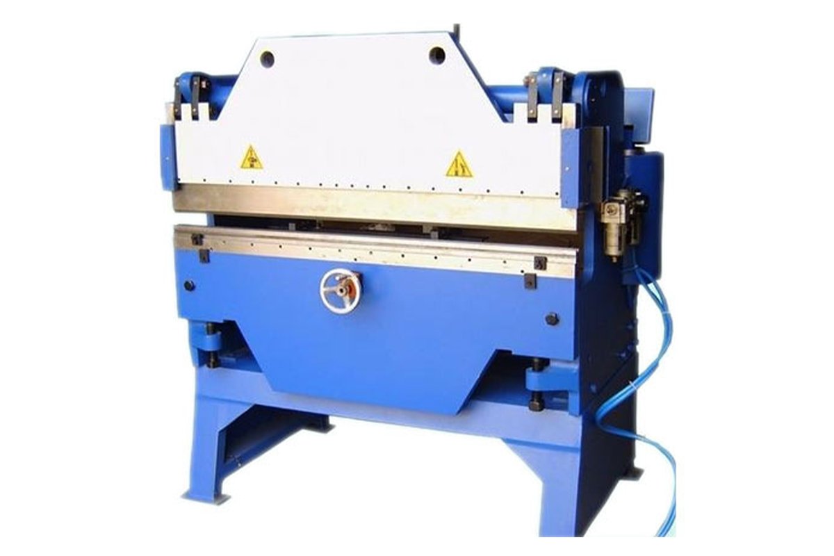
Q3: I have an old pneumatic press brake—still functional but lacking precision. Apart from selling it, what are my options?
- Definitive answer: Smart retrofitting is the most cost-effective way to breathe new life into it—better ROI than you might expect.
- Core concept: Upgrade from experience-driven “open-loop control” to data-driven “closed-loop control.”
- Implementation: Install a PLC (programmable logic controller) as the machine’s new “brain,” along with “sharp eyes” (angle/displacement sensors) and “precise nerves” (pressure sensors).
- Result: Your old machine will instantly gain advanced capabilities such as automatic angle compensation and pressure closed-loop control—features typically found only in modern equipment. Its precision and efficiency will improve dramatically, and it can even integrate seamlessly into automated production lines. It’s like transforming a classic vintage car into a self-driving smart vehicle.


