Knowing how to bend a 2 inch radius on a press brake is a key skill that separates proficient operators from true masters of the craft. This is not a standard bend; it is a unique challenge that involves stretch forming, significant material springback, and requires a deep understanding of tooling and material behavior.
This guide provides a definitive roadmap to mastering this advanced technique. We will cover everything from initial machine calibration and material-specific strategies to the two primary methods: dedicated tooling and segmented "bump" bending. Prepare to move beyond theory and gain the practical knowledge needed to achieve a perfect 2-inch radius with precision and confidence. For a more targeted deep dive, see Mastering Press Brake Bend Radius to expand your expertise in radius bending fundamentals.
I. Cognitive Upgrade: Why a 2-Inch Radius Bend Is a Unique Manufacturing Challenge
1.1 Redefining “Bending”: The Physics of Large-Radius Forming
Standard V-type bending focuses stress into a very small zone—defined by the punch tip radius and the V-die opening width—forcing the material rapidly into the plastic deformation stage. The process is more akin to “folding,” with the material’s elongation and flow tightly constrained.
When aiming for a large radius such as 2 inches, the physics change dramatically, especially when the internal radius-to-material thickness ratio (IR/MT Ratio) increases significantly. For example, with a 3 mm thick steel plate, a 2-inch radius yields an IR/MT ratio exceeding 16, transforming the forming process into something far different:
- From Bending to Stretching: This is no longer simple bending—it’s a process closely resembling stretch forming. Under the influence of the tooling, the outer layer of material must undergo substantial elongation to fill the large arc, while the inner layer experiences milder compression. Stress distribution becomes broader and more uniform rather than concentrated at a point.
- Elastic Deformation Takes the Lead: This is the key to understanding large-radius bending. Throughout the process, elastic deformation accounts for a far greater proportion than plastic deformation. A useful analogy: bending a thin wire into a sharp angle (small radius) is easy and results in permanent deformation; but bending a thick steel bar into a large curve requires immense force, and once released, it springs back toward its original shape. A 2-inch radius bend behaves exactly like the latter—material “memory” and resilience are fully on display.
1.2 Application Spectrum: Where and Why the 2-Inch Radius Matters
The 2-inch radius is not an arbitrary engineering choice—it serves industries where structural integrity, fluid dynamics, and industrial aesthetics demand exacting standards:
- Architecture & Decorative Structures: Curved curtain walls of large buildings, streamlined ceilings in airport terminals, and bridge railings. Here, a 2-inch radius ensures smooth, crease-free transitions—critical to achieving grand design statements.
- Transportation: Body panels, wheel arches, and bumpers for heavy trucks, trailers, and luxury RVs. Large-radius designs reduce aerodynamic drag, improve fuel efficiency, and evenly distribute impact forces in collisions, enhancing safety.
- Industrial Equipment & Enclosures: Casings for large automated machinery, conveyor guide rails in food processing, and large tanks or piping systems. Smooth arcs facilitate uninterrupted flow of materials or fluids, while eliminating hygienic dead zones for easier cleaning.
- Furniture & Art Installations: Designers of modern metal furniture and creators of public sculptures often use large-radius curves to achieve soft, continuous, yet visually dynamic forms.
In all these scenarios, a precise 2-inch radius is not just a functional necessity—it is a core design element determining the final product’s quality, safety, and value.
1.3 Key Challenges: Precision Control Is Everything
Compared to standard bending, the 2-inch radius bend’s difficulties revolve around one word: control. The four primary challenges are:
- Excessive Springback—the Unavoidable Nemesis: The number one enemy of large-radius bending. With elastic deformation dominating, the material experiences significant and unpredictable springback once the force is released. The higher the IR/MT ratio, the greater the springback angle and radius increase. Studies have shown that in extreme cases, springback angles can exceed 30 degrees and the final radius may be more than 60% larger than the tool radius—making simple experiential compensation virtually impossible.
- Thinning & Cracking—the Material’s Breaking Point: Under heavy stretching, the outer layer thins considerably. If elongation exceeds the material’s ductility limit, cracking becomes inevitable—especially in low-ductility materials like high-strength steels or certain hard aluminum alloys, or when grain orientation is unfavorable.
- Polygon Effect—the Illusion of a Smooth Arc: When simulating a large radius with step-bending, incorrect calculations for step count, spacing, or angle can result in a visibly segmented arc composed of short straight sections—a defect unacceptable in appearance-critical products.
- Surface Damage—the Aesthetic Flaw: With longer forming paths, greater contact areas, and increased sliding distances between material and tooling, any imperfection in the die surface, inadequate lubrication, or poor pressure control can leave scratches, imprints, or roller marks—ruining the product’s finish.
To master the 2-inch radius bend, conventional thinking must be abandoned. Success demands a complete upgrade in understanding—covering tooling selection, material properties, machine control, and process methodology. This is not just a technical challenge; it’s the ultimate test of process insight.
II. Setting the Stage: The Three Core Elements of Precision Bending (Tooling, Material, Machine)
Before pressing the “start” button, 90% of success is determined by preparation. For a master-level challenge like the 2-inch radius bend, the decisions and calibration accuracy made during setup dictate the upper limit of the finished product’s quality. The three core elements—tooling, material, and machine—form an interdependent “iron triangle.” Neglect in any one area leads directly to failure.
2.1 Tooling Selection—the Critical Decision: Matching Your 2-Inch Radius Target
Tooling choice—especially the V-die opening width—is the most critical, non-negotiable decision in forming a 2-inch radius bend. The wrong tool pairing will not only fail to produce the correct radius but can instantly damage the material and even cause irreversible harm to the equipment.
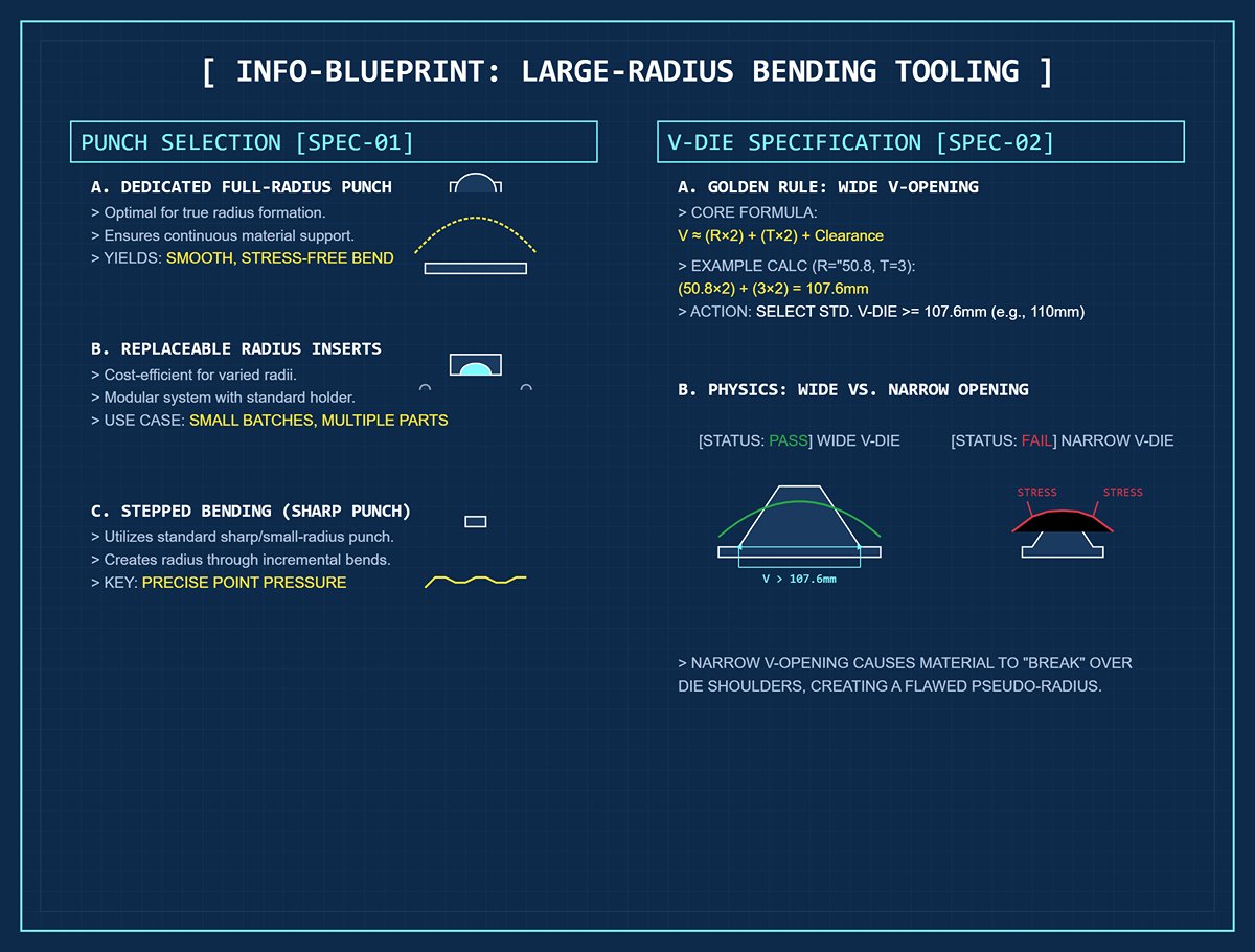
- Punch: The Precision Guide at the Heart of the Process
- Ideal Choice: Dedicated Full-Radius Punch — This is your ultimate tool for achieving a flawless 2-inch bend radius. The die’s entire contact surface forms a perfect 2-inch arc, providing continuous and even support throughout the bending process. It allows the sheet metal to wrap smoothly around the punch, resulting in a true radius with evenly distributed stress and a mirror-smooth finish.
- Versatile Alternative: Replaceable Radius Inserts — For operations involving multiple part types or small batch runs, this solution delivers outstanding cost efficiency. With a standard punch holder, you can easily swap low-cost inserts of varying radii to accommodate different bending requirements—from 2 inches to other sizes—with minimal setup effort.
- Stepped Bending Option — If you plan to use the “stepped bending method” introduced later, a specialized radius punch is unnecessary. A sharp punch or a standard small-radius punch will suffice—the key is its ability to deliver precise point pressure during each incremental step.
- Bottom Die (V-Die): The Decisive Factor
- Golden Rule: The V-opening Must Be Wide Enough! This is the core principle that distinguishes large-radius bending from conventional bending. A globally recognized guideline states: V-opening width ≈ (target inside radius × 2) + (material thickness × 2) + safety clearance.
- Practical Calculation Example: Suppose you’re bending a 3mm steel sheet to achieve a 2-inch (≈50.8mm) inside radius. Using the formula: (50.8mm × 2) + (3mm × 2) = 101.6mm + 6mm = 107.6mm. In real-world practice, choose the nearest larger standard V-opening—typically 110mm or 120mm.
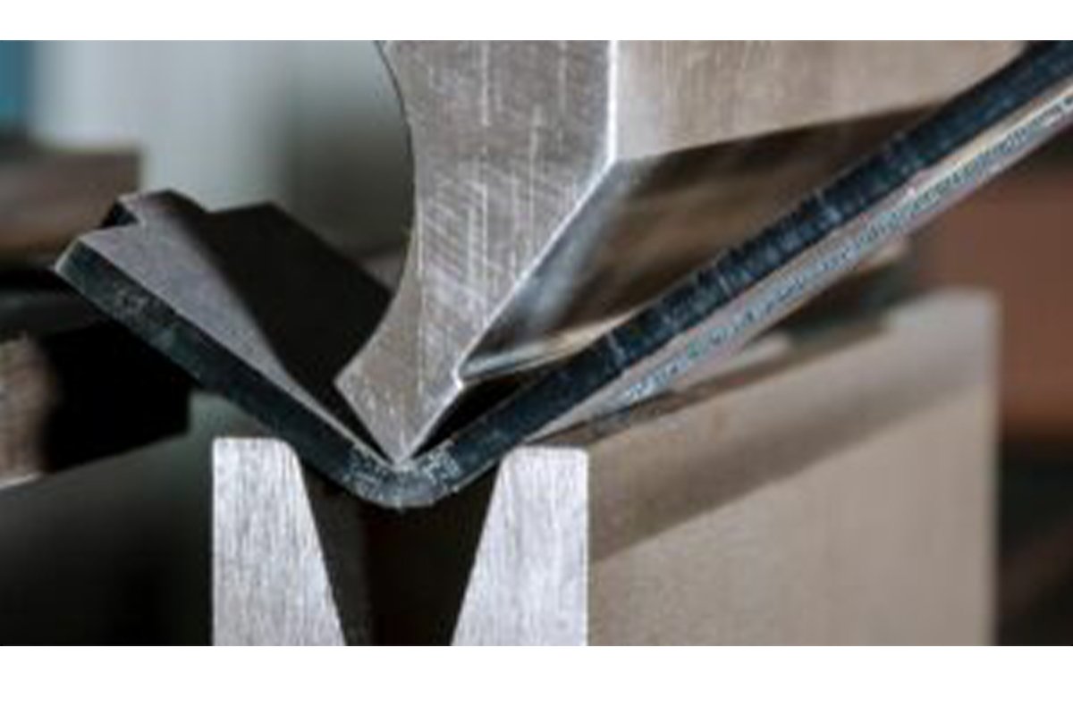
- The Physics Behind Wide V-Openings: In large-radius bending, our goal is for the material to be stretched and fully wrapped by the punch. If the V-opening is too narrow, the sheet will contact the die’s shoulders before the wrap is complete, creating two severe stress concentration points. This prematurely “breaks” what should be a smooth arc, producing a pseudo-radius with sharp transitions at both ends—an unacceptable flaw in any precision application.
2.2 Understanding Materials: Reading the Metal’s “Personality”
Entering the grade and thickness into your system isn’t enough. A true bending master reads each batch of metal much like a seasoned physician diagnosing a patient—observing, testing, and understanding its subtle behavioral traits before making adjustments.
- Material and Temper: The DNA of Ductility and Springback
- Mild Steel (e.g., A36) — Highly ductile with minimal, predictable springback. It’s considered the most “forgiving” material for large-radius bends and offers excellent process tolerance.
- Stainless Steel (e.g., 304) — Exhibits pronounced work hardening during bending. Each instant of deformation increases local hardness, heightening springback and making it harder to control. Precise overbend compensation is essential to achieve the intended radius.
- Aluminum Alloy (e.g., 6061-T6) — Limited ductility, especially in heat-treated T6 temper. It behaves like a brittle yet refined material—any excessive stretching can cause micro-cracks or outright fractures along the bend’s outer surface. As a rule, aluminum requires a larger bend radius than steel of equal thickness.
- Grain Direction: The Hidden Critical Factor
- Iron Rule: Never—under any circumstances—align your 2-inch bend line parallel to the material’s grain direction. Doing so is tantamount to design failure.
- Why It Matters: During rolling, the metal’s internal crystalline structure elongates, creating invisible texture lines—its grain direction. Bending along this direction (with the grain) is like trying to split wood along its grain—it maximizes stress at the weakest boundaries and leads to cracking. For large-radius bends, which demand extreme material elongation, that risk multiplies dramatically.
- Practical Strategy: During cutting or nesting (laser, plasma, or stamping), optimize your layout. Confirm with your programmer or cutting operator that all parts requiring large-radius bends have bend lines oriented 45° or 90° across the grain. This simple adjustment is the most effective and economical way to prevent cracking.
2.3 Machine Calibration and Parameter Setup
Machine condition is the final link between precise theoretical calculation and real-world accuracy. An uncalibrated press brake is like a rifle with a misaligned scope—it may shoot, but it won’t hit the mark.
- Tonnage Estimation and Validation: Debunking the “More Force is Better” Myth A common misconception is that large-radius bending demands high tonnage. In reality, the opposite is true. Wider V-dies distribute load over a greater area, so the required tonnage per linear inch is typically far less than that for sharp bends in narrow openings. However, your machine must maintain stable pressure output. Use a bending force calculator or the press brake’s internal database to estimate, ensuring your working pressure remains well below the machine’s maximum capacity.
- Open Height and Throat Depth: Anticipate Space Requirements Don’t overlook the finished part geometry. A 2-inch-radius 90° bend occupies considerable space both vertically and horizontally. During programming and tool setup, perform an interference check to confirm that the part won’t collide with the ram, back gauge, or throat of the press during bending or removal.
- Crowning Calibration: The Key to Consistent Radius Along the Entire Length This is the ultimate secret to achieving uniform radius across the full bend line—one that truly separates professionals from amateurs.
- Why It’s Critical: With wide V-dies, bending force acts across a larger span of the press brake. According to leverage mechanics, this amplifies natural machine deflection—causing the center to sag and the ends to rise, producing a subtle “banana” or “smile” shape.
- Consequences: Without proper crowning compensation, you’ll produce a radius that’s larger in the center and smaller at both ends—a “spindle-shaped” curve. For applications requiring seamless alignment, such as architectural panels or airtight enclosures, this deviation is entirely unacceptable.
- Action Item: Before starting large-scale production, it is essential to thoroughly inspect and recalibrate your press brake’s mechanical or hydraulic deflection compensation system. Conduct test bends using sample parts to measure and confirm that the bend angles and radii remain highly consistent from left to right and through the center. Ensure the compensation system delivers a precise, counteracting “crowning” force that matches your preset tonnage and bend length—so that, under load, the workbench remains as close as possible to a perfectly straight line.
III. Step-by-Step Practice: Complete Operating Blueprint for the Two Main Approaches
3.1 Method One: Dedicated Tool “Single-Forming” (Maximum Efficiency, Maximum Quality)
When a project demands peak precision, surface finish, and production speed, using a specially designed upper punch matched exactly to the target radius (a 2-inch radius punch) for air bending is the undisputed pinnacle. This technique does not brute-force the metal into shape; rather, it performs a graceful, highly controlled “stretch forming.” Through a single, smooth stroke—and with precise control near bottom dead center—the punch’s geometry naturally guides the sheet into a uniform, perfect 2-inch-radius curve.
Process Blueprint: A Five-Step Protocol from Calculation to Execution
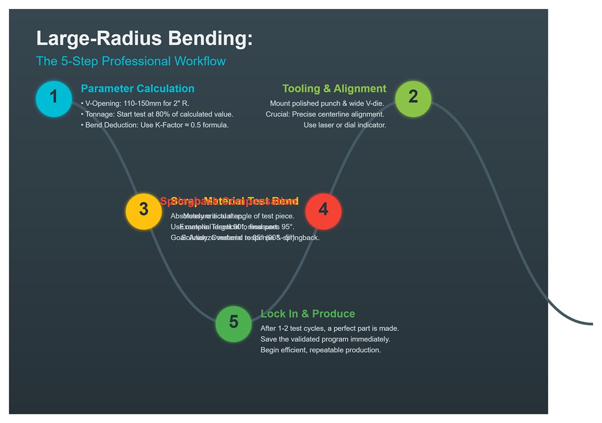
Step One: Foundation-Level Parameter Calculation
- V-Opening Width: Follow the golden rule established earlier. For a 2-inch (50.8mm) inner radius, the V-opening should typically range from 110mm to 150mm, depending on material thickness. This is a non-negotiable physical prerequisite.
- Tonnage Estimation: Use the press brake controller’s database or an online calculator. You will find, perhaps surprisingly, that the required tonnage is significantly lower than for sharp bends with a narrow V-opening. Begin your first test at roughly 80% of the calculated tonnage to ensure total safety.
- Flat Pattern Length and Bend Deduction: Set aside the K-factor tables you memorized for small-radius bending. In large-radius forming, the neutral axis shifts toward the sheet’s mid-thickness, making the K-factor nearly 0.5. A reliable starting formula is:
Bend Deduction ≈ (π/2 * (Inner R + Thickness * 0.48)) - (2 * (Inner R + Thickness)). Fine-tune this value through the upcoming test bends.
Step Two: Impeccable Tool Installation and Alignment
Securely mount the mirror-polished 2-inch radius punch and the wide V-die onto the press brake. Conduct an almost ritualistic alignment process using a laser alignment tool or a dial indicator to ensure the punch’s centerline precisely matches the die’s centerline along the entire bending length. Even a minute deviation will be magnified across a wide workpiece.
Step Three: The Moment of Truth – Test Bend with Scrap Material
This is an absolutely critical and irreplaceable step. Use scrap material that’s identical in alloy, thickness, and grain direction to the final part. Perform the first bend—not to produce a finished piece, but to “listen” to the material’s response and record its unique springback characteristics.
Step Four: Precise Compensation for Springback
Measure the test piece’s actual radius and actual angle using a radius gauge and a digital protractor. Suppose your target is 90°, but you measure 95°—that indicates 5° of springback. Adjust the CNC controller accordingly: 90 - 5 = 85° (i.e., “overbend” by 5°). The press brake will bend to 85°, and once the pressure releases, the material will spring back exactly to 90°. Likewise, fine-tune the Y-axis depth to match the exact target radius.
Step Five: Lock Parameters and Begin Efficient Production
After one or two cycles of careful testing and adjustment, you’ll produce a flawless part. Immediately save this validated program in the controller, paving the way for stable, efficient, high-quality batch production.
Advantages: Unmatched speed and consistency; superior surface quality with no faceted edges; extremely stable process requiring minimal operator intervention. Disadvantages: Higher upfront cost for custom tooling, unsuitable for prototypes or very small batches.
3.2 Method Two: “Step Bending” (Bump Bending) (Most Flexible, Most Economical)
When specialized large-radius tooling is unavailable—or when handling one-off prototypes, art pieces, or small production runs—the Step Bending Method stands out for its ingenuity and flexibility. It’s an art form that uses discrete points to approximate a continuous line. Employing a standard sharp punch or a small-radius tool, a series of precisely calculated, closely spaced minor bends gradually “sculpt” the desired large arc.
The principle is analogous to constructing a smooth curve from countless tiny line segments: the more segments (steps) you apply, the closer the result approaches a perfect arc—just as higher resolution yields finer image detail.
Process Blueprint: Mathematics Meets Craftsmanship
- Step One: Three-Part Mathematical Modeling (Core Calculation) This is the heart of step bending. Suppose we need to form a 90° arc with a 2-inch (50.8mm) internal radius on a 3mm-thick steel sheet.
- Determine Number of Steps (Segments): This defines the smoothness of the curve. A well-established rule of thumb is that each individual bend should not exceed 2°. To achieve a 90° arc, you could choose
90 / 1.5 = 60steps. The more steps, the less pronounced the polygonal effect. - Calculate Angle per Step (Angle per Bump):
Angle per Bump = Total Angle / Number of Steps. That is,90° / 60 = 1.5°. Allowing for springback, you may set the CNC program to 1.6° or 1.7° per step—the exact figure must be validated through test bending. - Calculating Step Distance: This defines how far the backgauge moves after each bend — the arc length of each incremental segment. The precise formula is:
Step Distance = 2 * π * (Inner Radius + K-Factor * Material Thickness) * (Angle per Step / 360). For larger radii, use a K-Factor of 0.5. Therefore,Step Distance = 2 * 3.14159 * (50.8 + 0.5 * 3) * (1.5 / 360) ≈ 1.37 mm.
The Blessing of Modern Technology: Fortunately, nearly all modern CNC press brake controllers (such as Delem or Cybelec) come equipped with built-in macros for “bump bending” or “radius bending.” There is no need for manual calculation — simply input total angle, target radius, material thickness, V-opening width, and either your preferred number of steps or segment chord length, and the controller automatically generates a complete program containing dozens of precise bend positions.
- Step Two: CNC Programming and Rhythmic Execution
- Automated Programming: Use the controller’s built-in macro. Input the defined parameters, and the system will generate a program listing each bend’s Y-axis depth and X-axis (backgauge) position.
- Execution and Quality Control:
- Rhythm and Consistency: Bump bending is a repetitive sequence — press the material against the backgauge, engage the pedal to complete a micro-bend, release, the backgauge retreats by one step, reposition the sheet, and repeat. This process demands exceptional patience and consistency from the operator. Each feeding position must be perfectly accurate and stable.
- Monitoring the “Polygon Effect”: After several bends, visually inspect the curvature. If you notice distinct edges, the step count is insufficient or the step distance has been miscalculated.
- Managing Cumulative Springback: Springback in bump bending accumulates with each pass. Once all bends are complete, measure the total angle. If it falls short, do not adjust the Y-axis depth (that would alter the radius); instead, slightly increase the programmed “angle per step” and re-run a full test sequence.
Advantages: Eliminates the need for costly specialty tooling; extremely flexible — capable of forming almost any large radius using standard tools. Disadvantages: Highly time-consuming and inefficient for production; final quality relies heavily on operator skill and consistency; inherently prone to the “polygon effect,” often leaving faint crease marks on the surface.
IV From Good to Great: Advanced Techniques and Quality Mastery
4.1 Mastering Springback: The Path to True Bending Mastery
Springback is metal’s inherent “memory.” Controlling it is essentially a process of erasing that undesirable memory and rewriting the correct geometry. In large-radius bending, elastic deformation overwhelmingly dominates, making this “memory” more pronounced — the greatest obstacle between theoretical calculations and practical results.
1. The Physics Behind It: Why a 2-Inch Radius Greatly Amplifies Springback
Imagine a small-radius bend as “folding a sheet of paper” — stress concentrates in a narrow zone, quickly pushing the material into plastic deformation. By contrast, bending to a 2-inch radius resembles “drawing a heavy bow.” Most of the applied energy is stored as elastic potential over a broad curved region. When pressure is released — akin to releasing the bowstring — that stored energy rebounds suddenly, causing the part to spring back aggressively. The result is a far greater angular and radial deviation than ordinary bends, and far harder to predict.
2. Accurate Prediction: The Three Levels of Springback Compensation

- Level One: Chart-Based Estimation (Beginner) — Quick and simple. Many tooling and material suppliers provide reference charts listing springback compensation values for various materials, thicknesses, and V-openings. Suitable for prototypes or non-critical parts, though insufficiently precise for batch variations.
- Level Two: Formula-Based Calculation (Intermediate) — Incorporates material properties such as Young’s modulus and yield strength, employing empirical formulas or finite element analysis (FEA) software for more accurate theoretical prediction. This approach demands solid engineering fundamentals, and its reliability still depends on input accuracy.
- Level Three: Trial-and-Iteration Method (Master) — The most dependable and precise strategy in practice. No theory can fully replicate real-world variables such as material batch inconsistency, hydraulic fluid temperature, or ambient humidity. A true master conducts one or two test bends using scrap identical in composition, thickness, and grain direction to the production material. By measuring the actual springback, they directly determine the required overbend angle — a literal dialogue with the material that eliminates all guesswork.
3. Beyond Overbending: Advanced Compensation Techniques
- Controlled Dwell Time: For materials prone to work-hardening (like stainless steel), do not retract the ram immediately upon reaching bend depth. In your CNC program, intentionally hold pressure (dwell) for 0.5–2 seconds. This brief pause allows disturbed metal lattices to realign and stabilize, effectively “locking in” the plastic deformation and significantly reducing springback. A near-zero-cost technique with unexpectedly powerful results.
- Limited Coining Technique: Building on air bending, apply a slight increase in tonnage to let the punch’s radius subtly imprint the inner bend surface. This introduces additional compressive stress at the bend root to counter tensile stress in the outer fibers that causes springback. However, such pressure must be controlled within micrometer precision — overdoing it risks leaving permanent surface marks.
4.2 Common Defects: Diagnosis and Remedies
An exceptional finished part is the outcome of countless potential defects being successfully prevented. The following table serves as a systematic, visual diagnostic guide to stop problems before they start.
| Defect | Deeper Cause Analysis | Precise Solution |
|---|---|---|
| Radius too large/too small | 1. Inaccurate springback compensation: the most common cause. 2. Incorrect V-opening selection: if the V-opening is too narrow, the material contacts the die shoulder before wrapping around the punch, forcing a smaller radius; too wide has the opposite effect. 3. Variations in material hardness between batches. | 1. Strictly apply the “trial bend iteration method” to recalibrate overbend angles and the bottom dead center. 2. Follow the golden rule V-Opening ≈ 2 × (R + T) when selecting or custom-making the lower die. 3. Test-bend each new batch of material before production. |
| Arc appears polygonal | 1. Insufficient steps: in step bending, excessive angle per bend creates noticeable straight segments. 2. CNC program lacks smoothness: uneven changes in angle or step spacing between adjacent bend points disrupt arc continuity. | 1. Greatly increase the number of steps, limiting each bend to no more than 2 degrees, ideally 1.5 degrees. 2. Use the controller’s built-in “arc interpolation” or “smooth transition” functions, or manually optimize the program to ensure perfectly uniform step rhythm. |
| Surface indentations/scratches | 1. Uneven pressure distribution: the root cause is not “too much pressure” but inconsistent pressure along the bend length. 2. Die contamination or damage: micro-defects, oxidation, or metal debris on the die surface. 3. Sliding friction: material shifts within a wide V-opening. | 1. Inspect and recalibrate the crowning compensation system to ensure uniform pressure along the entire length. 2. Clean dies thoroughly as you would a camera lens, and maintain the surface with fine-grit sandpaper or polishing compound. 3. Place urethane film in the lower die’s V-opening as a sacrificial layer to absorb friction. |
| Material cracking | 1. Violating minimum bend radius: for certain high-hardness or low-ductility materials, a 2-inch inner radius may still be too tight for the thickness. 2. Bend line parallel to grain direction: an unforgivable “original sin” in sheet metal work. 3. Bend speed too fast: insufficient time for plastic flow causes stress concentration and brittle fracture. | 1. Consult authoritative material manuals to confirm the bend radius is within safe processing limits; anneal if necessary. 2. During layout planning, ensure bend lines are oriented 45–90 degrees to the grain. 3. Significantly reduce ram speed in CNC programs to give the material time to “breathe.” |
| Radius inconsistent along length | 1. Machine deflection: the principal cause, especially with long bends; the machine may sag in the middle, enlarging the center radius. 2. Uneven die wear: central areas may wear faster over time. 3. Workpiece distortion from its own weight: long, narrow parts may droop at the ends during bending. | 1. Recalibrate the crowning compensation system—this is the only fundamental fix. 2. Regularly check die straightness, regrind or replace as needed. 3. Use adjustable front supports or rear-follow supports for long strip workpieces. |
4.3 Scientific Methods for Quality Inspection and Verification
In the vocabulary of precision manufacturing, “feel” is the least reliable term. Perfection must be defined by cold, objective data, supported by a systematic, repeatable verification process.
- Proper use of the basic toolkit:
- Radius Gauges: The fastest on-site inspection tool. Be aware of its limitations: it offers only point-contact contour comparison, unable to assess the continuity and uniformity of the entire arc. It can tell you whether the radius is correct at a given point, but not whether the whole arc is truly round.
- Digital Protractor: Used to precisely measure the final angle after bending, providing essential data for calculating springback and adjusting compensation.
- Advanced instruments for ultimate verification:
- Coordinate Measuring Machine (CMM): The definitive authority for validating large-radius arc geometry. A CMM probe can automatically collect hundreds of high-precision coordinate points along the arc surface, then fit them using software algorithms. The output is more than an average radius—it also delivers critical geometric tolerances such as roundness and profile accuracy, defining a “perfect arc” with scientific precision.
- Laser Scanners: As a powerful complement to CMM, these non-contact devices can rapidly capture massive 3D point cloud data from a workpiece’s surface. When full-scale contour analysis is required, they offer unmatched efficiency.
From mastering the subtle art of springback control, to applying rigorous logic in defect diagnosis, and finally to using scientific verification methods—this pursuit of excellence forms the path from acceptable to outstanding. It is not only a refinement of technique, but also a steadfast commitment to an engineering spirit that seeks perfection.
V. Tailored Strategies: Large-Radius Bending Guides for Mainstream Metals
5.1 Stainless Steel (304 as an example): Precision Tactics Against Work Hardening
304 stainless steel, the “elegant knight” of the sheet metal world, is renowned for its exceptional corrosion resistance and lustrous surface. Yet beneath its refined exterior lies a stubborn temperament—pronounced work hardening.
- Core Challenge: During every moment of bending, the austenitic crystal structure undergoes phase transformation, causing hardness and strength to rise sharply—like wrestling an opponent who grows stronger with each move. The direct consequences are enormous, unpredictable springback forces. Additionally, stainless steel’s surface is prone to galling, where it seizes or adheres to the die. Even the smallest oversight can leave permanent, irreparable marks on its mirror-like finish.
- Specialized Strategy:
- Aggressive Overbend Compensation: Discard the 3–5° compensation rule of thumb you use for carbon steel. For 304 stainless steel with a 2-inch radius, start by planning for an overbend of 10 to 20 degrees—or even more. The only reliable guide is real-world testing: perform an initial trial bend, measure the actual springback, then decisively and precisely apply the required compensation angle.
- Tai Chi–Style Slow Bending: In your CNC program, reduce the ram’s bending speed to 30%–50% of the normal rate. A slow, steady deformation—like practicing Tai Chi—helps limit the instant heat buildup caused by friction and plastic deformation, physically reducing work-hardening and making the material more cooperative.
- Unlock the “Dwell Time” Secret: When the ram reaches its lowest point (Y-axis limit), don’t retract immediately. Add a dwell time of 1–2 seconds. This brief pause is a cost-effective, highly effective way to minimize stainless steel springback. It allows the disturbed crystal lattice inside the metal a crucial moment to realign and stabilize, locking in more of the desired plastic deformation.
- Flawless Tooling and Protection: Use mirror-polished, hardened steel dies with a Rockwell hardness above 60 HRC—this is essential to prevent surface scratching. For the highest surface quality, place a thick urethane film inside the lower die’s V-opening. Treat this not as an optional step, but as a standard procedure.
5.2 Aluminum Alloy (6061-T6): Dancing on the Edge of Fracture
6061-T6 aluminum alloy is a favorite in aerospace and high-performance structural applications, prized for its exceptional strength-to-weight ratio. Yet its T6 temper grants high hardness at the cost of ductility, making it behave like a proud but short-tempered gentleman—its ability to stretch is extremely limited.
- Core Challenge: Under the heavy tensile stress of a 2-inch radius bend, the outer fibers of 6061-T6 can quickly reach their elongation limit. The result is not gradual distortion, but sudden, catastrophic cracking. For this material, springback is a secondary concern—preventing fracture is the top priority driving every aspect of the process design.
- Special Strategy:
- Consult the “Material Bible” – Minimum Bend Radius: Before starting, consult authoritative references such as the ASM Handbook to confirm that your 2-inch (50.8 mm) target radius is greater than or equal to the recommended minimum bend radius for your sheet thickness. If it’s smaller, no amount of technique will prevent failure.
- Grain Direction Is a Life-or-Death Factor—No Middle Ground: For low-ductility materials like 6061-T6, the bend line must be perpendicular to the rolling grain direction (cross-grain bending). This is the single most important and effective rule for avoiding cracks—any deviation, even 45°, carries unacceptable risk.
- Choose Dies with a Gentle Touch: To give the material fibers the smoothest transition possible, consider using an upper die with a slightly larger radius than the target. For example, a 2.25-inch radius punch can be fine-tuned at bottom dead center so that, after springback, the finished part safely approaches the 2-inch radius goal.
- Widen the V-Opening Beyond the Norm: Starting from the golden rule
V-Opening ≈ 2 × (R + T), add an extra 10%–15% width. This minimizes contact stress between the material and the die shoulders, giving the outer surface fibers maximum freedom during tension.
5.3 Thick Plate (>6 mm): Confronting Sheer Force and Deflection Head-On
Once material thickness exceeds 6 mm (about 1/4 inch), every challenge of a 2-inch radius bend intensifies exponentially. This is no longer just about technique—it becomes the ultimate test of machine rigidity, tonnage capacity, deflection compensation accuracy, and operational safety.
- Core Challenges:
- Extreme Tonnage Requirements: Even with a very wide V-opening, the force needed to bend thick plate is enormous, enough to overwhelm many small or medium-sized press brakes.
- High-Energy Springback and Safety Hazards: Thick plate springback is no gentle release—it’s a violent snap, unleashing enough energy to misalign dies or eject parts, posing serious danger to operators and equipment.
- Deflection Becomes the Dominant Factor: The immense pressure can visibly bow the ram and worktable into a “smile” shape (center sag). This is the primary and most stubborn cause of a larger radius in the middle of the bend and smaller radii at the ends.
- Special Strategy:
- Safety Above All Else: Use a bend force calculator to precisely estimate the required tonnage, ensuring it stays within 80% of the machine’s rated capacity. Clear the work area and mandate the use of cranes, robotic arms, or other lifting devices for handling and positioning the workpiece.
- Engage and Fine-Tune Deflection Compensation: For large-radius bends in thick plate, a fully functional and precisely calibrated hydraulic or mechanical deflection compensation system is non-negotiable. Without it, achieving a consistently uniform arc along the entire length is virtually impossible.
- Step Bending Is the Smarter Choice: Fabricating a dedicated 2-inch radius die for thick plate would be prohibitively expensive, heavy, and cumbersome to change. In this case, step bending offers overwhelming advantages in cost, flexibility, and safety—breaking one massive force application into dozens of smaller, controlled energy releases.
- Use “Breathing” Incremental Pressure: Even within each step bend, you can apply a more refined approach: try a rhythm of “pre-press to 50% depth – brief pause or slight retraction – continue pressing to full depth.” This breathing-style pressure gives internal stresses a moment to dissipate and redistribute, resulting in a more stable and precise final form.
VI. Conclusion
Mastering how to bend a 2-inch radius on a press brake transforms a complex challenge into a repeatable, high-value capability. We've covered the essential strategies—from material-specific tactics and precise calculations to the distinct advantages of dedicated tooling versus bump bending.
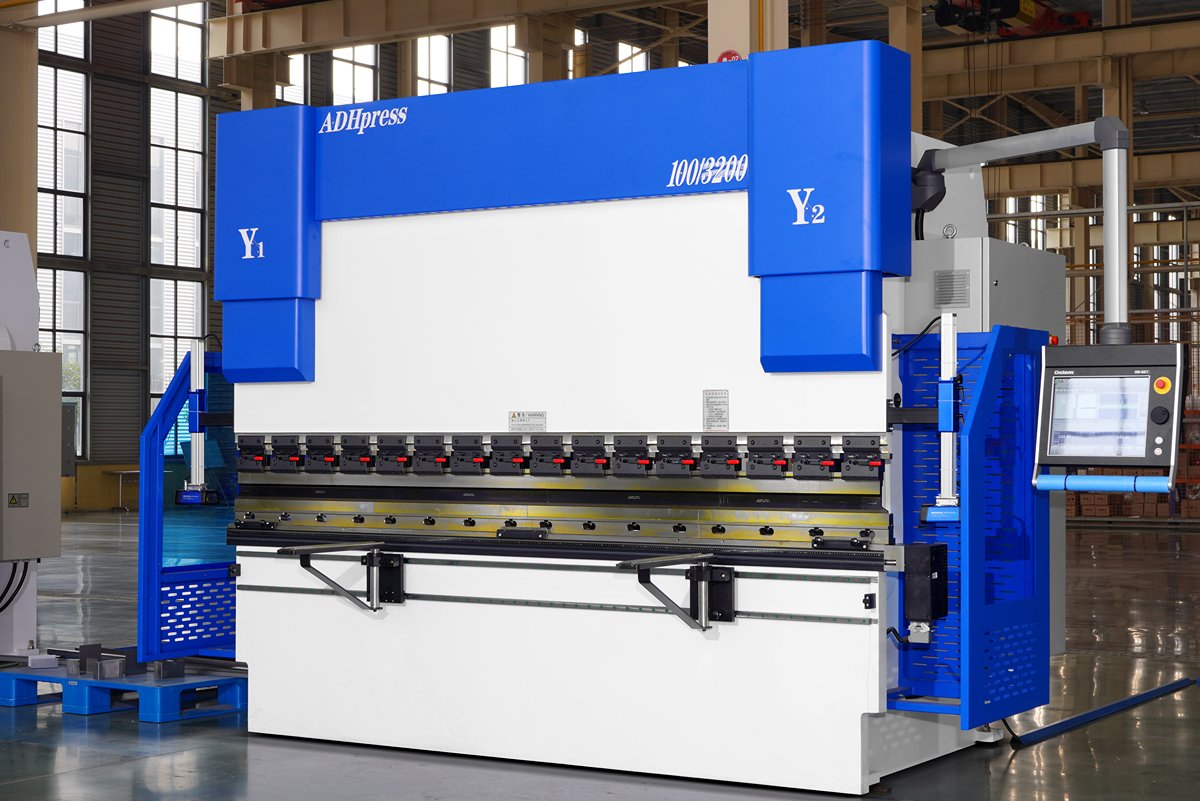
You now have the expert framework to control springback, diagnose defects, and produce flawless results consistently. Ready to apply this expertise? The team at ADH Machine Tool provides the industry-leading machinery and support necessary to turn your most ambitious designs into reality.
You can explore our detailed Brochures to learn more about our product range, specifications, and application cases. If you have specific project requirements or need personalized guidance, feel free to contact us today to advance your fabrication capabilities.


