I. Understanding Press Brake U Bends
In the world of precision metal forming, U-bending is a fundamental yet highly challenging process. Reducing it to "two consecutive 90-degree bends" greatly underestimates its complexity and strategic significance. To truly master efficient and precise U-shaped forming, one must go beyond geometry and develop a deep understanding of its physical principles, industrial role, and process limitations—a full cognitive upgrade, so to speak.
1.1 History and Evolution of Press Brake Technology
The press brake is considered a pivotal precision sheet metal forming equipment, and its history can be dated back to early industrialization. The initial manual press brake depends on the labor force, which features complex operation and low efficiency.
With the advancement of technology, hydraulic and CNC technology significantly improve the development of the press brake, making the machine able to proceed with precise and intricate bending, including u bend.
U bend technology is constantly upgraded with the evolution of press brake technology, which ranges from simple straight-line bending to three-dimensional bending. Not only achieving improved apparently bending angle and precision but also realizing multi-step sequence automatic constant bending.
Modern CNC press brakes can even be integrated with CAD/ CAM software, precisely imitating and controlling the overall u bend, achieving high precision and mass production projects. What’s more, the die technique and assistant tools, like the back gauge and front support device, also further enrich and improve the possibility and adaptability of the u-bend.
1.2 Core Concept Analysis: U-Bending Is Far More Than Two 90-Degree Bends
U-bending refers to the process in which a sheet of metal is shaped into a U-profile through one or several strokes of a press. Its essence lies not in replicating geometry but in skillfully controlling the physical behavior of the metal itself—a refined art of mastering material mechanics.
- Geometry, Stress Distribution, and Unique Mechanisms of Plastic Deformation
When the punch presses into the sheet, a complex stress field develops within the material. The outer layer (farthest from the punch) experiences intense tensile stress, stretching its atomic lattice, while the inner layer (in contact with the punch) undergoes compressive stress, squeezing the lattice. Between these two zones lies a theoretical layer that is neither stretched nor compressed—the Neutral Axis.
A crucial yet often overlooked phenomenon is that during bending, this neutral axis shifts noticeably toward the compression side. This displacement directly affects the actual material elongation and is the foundation for accurately calculating the developed length. - Internal Stress, Springback, and Material Elongation
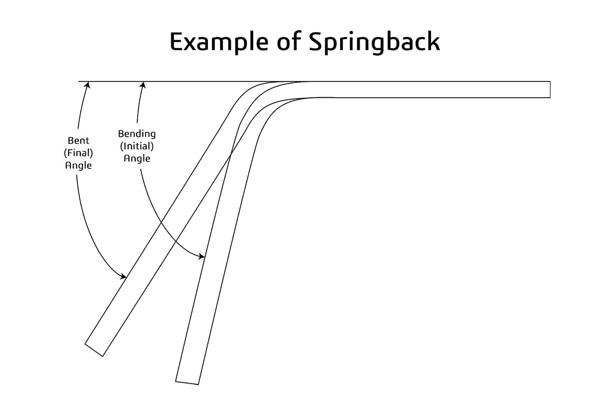
The Physics Behind U-Bending When the bending moment’s induced stress exceeds the material’s Yield Strength, permanent plastic deformation occurs. Unlike V-shaped “air bending,” U-bending involves deeper plastic flow. Once the pressing force is released, the imbalance of internal Residual Stress—generated by both tensile and compressive effects—drives the material to redistribute stress, causing partial rebound at the corners and sidewalls. This phenomenon, known as Springback, is particularly complex in U-bending because both corners interact and influence each other.
Achieving dimensional precision requires exact compensation through techniques like overbending and bottoming. Moreover, tensile strain on the outer layer leads to thickness reduction, a critical factor that must be calculated and controlled during precision U-shaped component design.
1.3 Key Roles in Industrial Applications: Why U-Bending Matters
Thanks to its unique geometry and one-piece forming capability, the U-bent component has become indispensable in multiple high-tech industries. The forming quality directly affects the product’s precision, structural strength, and overall performance.
- Typical Application Scenarios
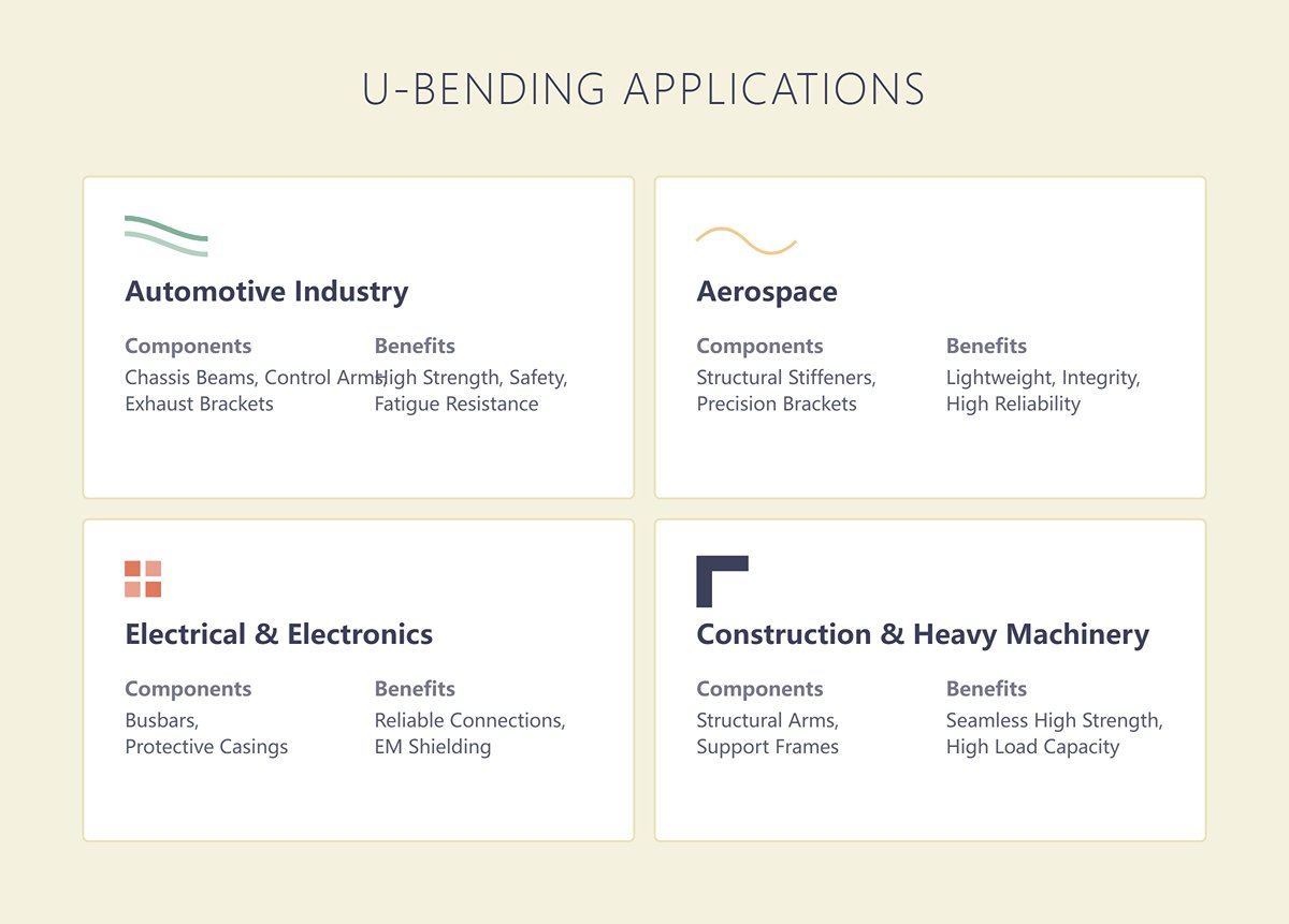
- Automotive Industry: From chassis reinforcement beams and control arms in suspension systems to complex exhaust brackets, U-section components are the structural backbone of vehicle safety and performance due to their high strength and fatigue resistance.
- Aerospace: In aircraft manufacturing, where both lightweight construction and reliability are paramount, U-bending is used to produce structural stiffeners and precision brackets for hydraulic and fuel systems. Even minimal deviations in these components can compromise the integrity of the overall structure.
- Electrical and Electronics: U-shaped busbars in large electrical cabinets carry substantial currents, where dimensional consistency ensures the reliability of electrical connections. In precision electronic devices, U-shaped casings provide both structural support and electromagnetic shielding.
- Construction and Heavy Machinery: Structural arms in heavy equipment and support frames in building façades often employ thick-plate U-bending processes. This technique yields seamless, high-strength components capable of withstanding enormous loads.
1.4 Process Comparison: Fundamental Differences Between U-, V-, and Groove Bending
To fully grasp the uniqueness of U-bending, it helps to compare it with more common processes such as V-bending and groove bending. The three differ significantly in forming path, die design, and technical challenges.
| Characteristic Dimension | U-Bending | V-Bending | Groove Bending / V-Grooving |
|---|---|---|---|
| Core Principle | Uses a U-shaped punch and die to form two bends simultaneously around the punch in one or more press strokes. | The most versatile method; a V-shaped punch presses the sheet into a V-die to form a single bend. | Prior to bending, a shallow V-groove is machined along the bend line; the sheet is then bent using standard tools. |
| Forming Path | Material is fully constrained within the die and undergoes complete plastic flow—both sidewalls form at once. | Path flexibility allows for air bending, bottoming, or coining, depending on punch depth. | Deformation occurs in the thin layer left at the groove, much like folding paper. |
| Die Design | Highly specialized—width, depth, and radius of die directly determine final geometry; often custom-built. | Highly universal—one V-die set can form multiple angles and thicknesses by adjusting parameters. | Requires additional grooving equipment; die accuracy is moderate, but groove precision is critical. |
| Technical Challenges | Extremely complex springback behavior: mutual interference between two sides makes prediction and compensation difficult. Maintaining sidewall parallelism and dimensional accuracy demands precise control of pressure and dwell time. | Springback is the key challenge (notably in air bending); accuracy relies heavily on CNC compensation capability. | A longer process chain—requires meticulous control of groove depth, width, and position; otherwise, cracks may occur. |
| Unique Advantages | High efficiency and consistency: single-stroke forming ideal for mass production. Structural integrity: one-piece, weld-free design ensures superior strength. | Exceptional flexibility: can achieve nearly any bending angle from sharp to obtuse; best overall adaptability. | Virtually no springback: minimal residual stress. Enables extremely small bend radii and sharp corners with flawless surface finish. |
| High-Value Applications | Ideal for high-strength, dimensionally consistent structural components, channels, rails, or brackets—performance unmatched by other methods. | The standard technique for most sheet-metal parts; the foundational process for complex assemblies. | Irreplaceable in premium architectural finishes, elevator cabins, and luxury showcases where aesthetics and razor-sharp edges are essential. |
In summary, the technical intricacy of U-shaped bending lies in the profound understanding and precise control of material plastic deformation and complex springback behavior. Its immense industrial value stems from the ability to produce high-performance core components—key pillars of modern industry—with high efficiency and consistency. Grasping this truth marks the first step in a craftsman’s journey from ordinary operator to true process master.
Ⅱ. Foundational Decisions: Selecting the Right Equipment and Tools for Precision U-Bending
If a deep grasp of physical principles forms the inner strength, then choosing the right equipment and tools is the act of forging a sword that slices clean through steel. In the real-world practice of U-shaped bending, any attempt to achieve precision with unsuitable tools inevitably leads to costly failure. In this section, we will dissect the three foundational pillars of U-bending decision-making—press brake selection, tooling systems, and process strategies—equipping you with an unassailable framework of hardware and methodology.
2.1 Choosing the Engine: In-Depth Comparison and Decision Matrix for Press Brake Types
The press brake is the power core of the bending process. Its drive mechanism, control accuracy, and structural rigidity fundamentally determine both the achievable precision limit and the overall efficiency of U-shaped bending.
- Mechanical vs. Hydraulic vs. Electric/Servo vs. Hybrid
- Mechanical Press Brake: Powered by a flywheel that stores energy and releases it via a clutch, this machine offers exceptionally high punching speed and repeatable positioning accuracy. Its fatal flaw, however, is a fixed stroke and uncontrollable pressure. For U-bending processes that require fine control of over-bend to compensate for springback, the mechanical type is largely ineffective—best suited only for high-volume, simple U-shaped stampings.
- Hydraulic Press Brake: Controlled by proportional or servo valves that govern hydraulic flow and pressure, this is currently the industrial standard. It delivers immense tonnage with fully adjustable stroke and pressure, making it the ideal choice for thick plates and large U-shaped parts. Its pressure-holding capability is critical for minimizing sidewall springback and ensuring geometrical accuracy. The drawbacks are slower response speed and higher energy consumption during continuous operation.
- Servo-Electric Press Brake: Driven directly by a high-powered servo motor through precision ball screws or timing belts, its responsiveness is unmatched. Positioning accuracy easily reaches micron-level (±0.002 mm), and it consumes power only during motion—making it exceptionally energy efficient. This type is perfect for applications demanding extreme precision, speed, and repeatability (such as electronics housings or medical devices), though its tonnage capacity limits its use for heavy-gauge materials.
- Hybrid Press Brake: This design merges the hydraulic system’s muscle with the servo drive’s intelligence. It uses servo motors to power hydraulic pumps on demand, combining high tonnage with rapid response, precise control, and outstanding energy savings. Representing the future of high-performance bending technology, hybrids deliver high precision, high efficiency, and low energy consumption—though they demand the highest initial investment.
- CNC Automation Revolution: The Leap from Craftsmanship to Science The CNC (Computer Numerical Control) system serves as the "brain" of a modern press brake. It has transformed U-shaped bending from an experience-driven craft into a programmable, predictable, and repeatable engineering process. For U-bending, CNC technology offers the following advantages:
- Multi-Step Programming and Simulation: It allows advance planning and simulation of complex multi-step bending sequences, automatically detecting and avoiding clashes between the workpiece, machine, and tooling—a crucial feature for deep U-channels and irregular shapes.
- Y-Axis Precision Control: Manages ram depth with accuracy down to 0.01 mm or better, enabling perfectly consistent bend angles.
- Springback Compensation Database: Together with angle measurement systems, it automatically corrects for material springback, ensuring angle consistency throughout mass production.
- Deflection Compensation (Crowning) Control: For long U-shaped components, CNC systems automatically adjust for machine deflection under load to maintain straightness across the entire bend length.

- Equipment Selection Decision Matrix
Choosing the right machine is a matter of precise balance between application requirements. The following table offers a clear guideline for decision-making:
| Decision Factor | Mechanical | Hydraulic | Servo-Electric | Hybrid | Core U-Bending Considerations |
|---|---|---|---|---|---|
| Material/Thickness | Thin to medium sheets | Suitable for all thicknesses; required for thick plate | Thin to medium sheets | Medium to thick | For thick plate (>6 mm) U-bending, hydraulic or hybrid systems are starting points. |
| Production Volume | High-volume, simple parts | Small to medium batches; high flexibility | Small to medium batches; mixed production | Medium to large batches | Servo-electric systems excel in high-mix, low-volume flexible production with fast setup and response. |
| Accuracy/Repeatability | Moderate | Good (depends on CNC) | Excellent (±0.002 mm) | Excellent (±0.002 mm) | For aerospace and precision electronics U-shaped parts with tight tolerances, servo or hybrid systems are essential for yield consistency. |
| U-Channel Complexity | Limited | High | Very high | Very high | Complex U-channels require CNC control of stroke and pressure profiling; the last three options are suitable. |
| Tonnage Requirement | High | Highest | Limited | High | U-bending demands higher tonnage than V-bending; precise calculation based on material, thickness, and die width is critical. |
| Stroke/Throat Depth | Fixed | Adjustable, long stroke | Adjustable | Adjustable, long stroke | Deep U-channels or large-flanged parts require greater machine open height and throat depth to prevent interference. |
| Initial Investment | Low | Medium | High | Highest | Budget constraints are real, but lifecycle cost should guide the decision. |
| Operating Cost | Medium | High | Very low | Low | Servo and hybrid presses deliver significant long-term savings through superior energy efficiency, embodying sustainable manufacturing. |
2.2 The Core Weapon: Mastery and Configuration Strategies of U-Bending Tooling Systems
If the press brake is the arm, then the tooling is the hand—the part that directly shapes and defines the soul of the workpiece. A well-designed and properly matched tooling system is every bit as valuable as the machine itself.
- Upper Die (Punch) Selection: The Art of Space and Form
- Standard Straight Punch: Suitable for shallow or wide U-bends where interference risk is minimal; versatile and reliable.
- Gooseneck Punch: Recognizable by its backward-curving profile, this tool is indispensable for U-bending. It provides essential clearance for pre-formed flanges, making it the only choice for producing deep U-channels, box shapes, or nested contours without collision.
- Custom Punch: When faced with extremely deep, narrow, or intricately contoured U-shaped designs, standard tooling fails. In such cases, custom punches must be developed based on the product’s 3D model.
- Lower Die (Die Block) Matching: The Precision Geometry Challenge The U-shaped lower die’s opening width, depth, and shoulder radius must be precisely matched to the material thickness and required internal dimensions.
- Die Width: This parameter governs the bend radius, required tonnage, and springback behavior. A well-established guideline is the “8× Sheet Thickness Rule”: for mild steel with a tensile strength around 450 MPa, the V-opening of the lower die (V) should be eight times the material thickness (T). For more ductile stainless steel, increase this ratio to 10–12×; for softer aluminum, reduce it to about 6×. Ignoring this rule can lead to inaccurate dimensions in mild cases or severe problems such as cracking and machine overload in worse ones.
- Shoulder Radius: The radius at the lower die’s shoulders must be sufficiently large and meticulously polished to prevent scratches or pressure marks on the workpiece surface—particularly critical for stainless steel and aluminum parts where appearance matters.
- Advanced Die Solutions: Going Beyond Tradition: As the demand grows for high-value products requiring flawless finishes and superior adaptability, conventional steel dies struggle to keep up. The following cutting-edge approaches are redefining quality standards in U-shaped bending operations:
- Roller Dies: Replace the fixed shoulder radius with freely rotating, hardened steel rollers. As the sheet is pressed into the die, the rollers turn, transforming damaging sliding friction into protective rolling contact. This innovation virtually eliminates surface scratches—especially on coated or brushed sheets—reduces bending force by up to 20–30%, and improves springback consistency.
- Urethane Inserts/Pads: When working with mirror-finished stainless or pre-coated sheets that demand zero surface damage, embed high-hardness urethane (an engineering elastomer) inserts inside the steel die cavity. During bending, the urethane deforms elastically to gently cradle the part, completing the bend without leaving any marks and enabling truly “mark-free” forming.
- Adjustable Dies: Using hydraulic or mechanical systems, operators can automatically alter the V-opening width within seconds to accommodate various sheet thicknesses for U-shaped bends. This completely overturns the old, crane-dependent die change process—ushering in flexible production and dramatically shortening delivery times.
- The Golden Rule of Dies: How the V-Opening “Programs” the Bend Radius
In the widely used air bending process, a counterintuitive yet crucial fact emerges: the final internal bend radius (Ir) is not defined by the punch tip radius but is instead “naturally shaped” by the die’s V-opening width (V).
This relationship can be expressed succinctly as Ir ≈ V × C, whereCis a coefficient related to material ductility—approximately 0.15–0.17 for mild steel, 0.20–0.24 for stainless steel, and 0.12–0.14 for soft aluminum. This means that by selecting dies with different V-widths, operators can precisely “program” the desired radius.
For example, bending mild steel with a 32 mm V-opening will produce a roughly 5 mm inner radius (32 × 0.156). Fully grasping and applying this principle marks the transition from trial-and-error operator to predictive process expert.

2.3 Process Strategy Selection: Planning the Forming Method
Even with top-tier equipment and dies, success depends on the right strategic approach. Choosing the appropriate forming process for different U-shaped profiles and precision requirements directly determines both efficiency and outcome.
- Single-Hit Forming: Uses perfectly matched upper and lower U-dies to form the shape in a single press stroke. This method delivers unmatched efficiency and consistent accuracy, making it ideal for mass production of regular, moderately deep U-profiles.
- Multi-Step Forming: For deep or narrow grooves, or asymmetrical U-parts, one-step forming can cause excessive stretching, wrinkling, or tool interference. In such cases, a multi-step approach is required—for instance, pre-bending two obtuse angles with a V-die first, then performing final shaping with a flattening die. Though more complex, this divide-and-conquer strategy enhances process flexibility and mastery of intricate shapes.
- Air Bending vs. Bottoming vs. Coining: Balancing Precision, Appearance, and Cost These three bending methods represent distinct manufacturing philosophies in U-shape forming:
- Air Bending: The punch presses the sheet into the lower die but doesn’t reach the bottom; bend angles are entirely controlled by punch depth (Y-axis positioning).
- Advantages: Requires the least tonnage and offers exceptional flexibility—one die set can produce numerous angles and radii by simply adjusting the machine program. It’s the mainstream method for modern CNC press brakes.
- Challenges: Springback is the primary obstacle; final accuracy relies heavily on the machine’s positional repeatability and the CNC system’s ability to compensate for springback.
- Bottoming / Bottom Bending: The punch continues downward until the sheet’s inner surface contacts the punch and the outer surface rests on the die’s shoulders.
- Advantages: A light “ironing” effect minimizes springback and greatly improves angular consistency. Required tonnage is moderate—roughly two to four times that of air bending.
- Challenges: Die angle precision must be extremely high, and each die can produce only one fixed angle, limiting flexibility.
- Coining: Uses extremely high tonnage (five to ten times that of air bending), forcing the punch tip deep into the material so intense plastic deformation occurs at the bend root, thinning the sheet.
- Advantages: By completely erasing material elasticity, springback is virtually eliminated, achieving superior angular precision and tiny inner radii.
- Challenges: The immense force drastically wears machines and dies, shortening their lifespan, and leaves visible imprints on the part surface. Except for special precision applications, coining is now rarely used in modern U-bending.
In precision U-bending practice, CNC-based air bending forms the foundation of efficiency thanks to its adaptability and intelligent compensation capabilities, while bottoming remains the preferred technique for high consistency. The true artistry of an expert lies in understanding these subtle distinctions and choosing the optimal balance between cost, efficiency, and precision for each specific part.
Ⅲ. Field Manual: Step-by-Step Process for Achieving Flawless U-Bends
Theory lays the foundation, but true mastery comes only through relentless hands-on practice. If the previous chapters served as your strategic map, this one is your field survival guide. Here we present a precise, fully detailed step-by-step workflow—from preparation to inspection—designed to transform theoretical knowledge into repeatable, high-quality production results. Its ultimate aim is to minimize errors and push you closer to the ideal of “zero defects.” Every step captures lessons born of countless successes and failures.
3.1 Preparation Phase: Strategic Selection of Molds and Parameters
Half of the success in U-bending depends on decisions made before the first fold. Once the foundation is wrong, even the finest technique cannot salvage the outcome. Choosing the right combination of mold and parameters forms the cornerstone of perfection—it’s what separates the professional from the amateur.
3.1.1 Upper Die Selection: When to Use Gooseneck and Straight Punches
The choice of the upper die (punch) determines both the bending strategy and the feasibility of the final U-shape. It’s not a simple selection—it’s a strategic decision rooted in geometric precision and mechanical logic.
- Straight Punch:
- Optimal Use: The straight punch excels in the single-step U-channel forming method, typically partnered with a dedicated U-shaped lower die. When the U-channel is shallow and wide, and maximum efficiency is the goal, its simple structure and exceptional rigidity deliver immense forming pressure—making it the undisputed choice.
- Expert Insight: The thick cross-section of a straight punch minimizes elastic deformation under high tonnage, crucial for ensuring a perfectly flat channel bottom and uniform side angles. In applications that involve bottom compression or coining, this rigidity advantage becomes even more pronounced.
- Gooseneck Punch:
- Optimal Use: This tool is indispensable in two-step or multi-step sequential bending. Its characteristic “gooseneck” shape is designed to create clearance—providing vital space for the previously formed flange, allowing the second bend to occur without catastrophic interference. When the flange height exceeds half of the channel’s bottom width, the gooseneck becomes virtually mandatory.
- Critical Trade-off: The neck of the gooseneck punch is its defining strength and potential weakness. Choosing one involves balancing clearance and rigidity. A practical rule of thumb: Always select the shortest, strongest neck that still avoids interference. Overly slender goosenecks may flex invisibly under pressure, manifesting later as inaccurate angles—a subtle but costly punishment.
3.1.2 Lower Die Selection: Decision Logic for V-Dies, U-Channel Dies, and Multi-Station Dies
The choice of lower die directly influences the efficiency, precision, and cost of producing U-bends.
- V-Die:
- Decision Logic: The most flexible and cost-effective universal option. Ideal for small batches, varied styles, and frequent size changes, it forms the U-shape by performing two distinct bends—making it the standard component in the “two-step sequential bending method.”
- Core Consideration: The V-die angle compensates for material springback. To achieve a precise 90° U-bend, the die angle must be slightly smaller—typically 88°, 85°, or even 82° for high-springback materials like stainless steel.
- U-Channel Die:
- Decision Logic: The ultimate solution for high-volume, high-precision, high-efficiency production. Paired with a straight punch, it achieves near-perfect channel geometry in one stroke. When tight parallelism between walls and flawless bottom flatness are required (e.g., precision rails or sliding components), a dedicated die is the only route to success.
- Hidden Costs and Gains: While initial investment is high, the U-channel die eliminates multiple setup and bending cycles. Over tens of thousands of repetitions, savings in time, labor, and scrap—caused by accumulated positioning errors—far outweigh the upfront expense.
- Multi-V or Multi-Station Die:
- Decision Logic: Tailored for complex parts requiring various U- or V-bends on the same sheet. By integrating multiple dies into one base, it reduces die-change time from minutes to virtually zero—a cornerstone technique for one-piece flow and flexible manufacturing systems.
3.1.3 The Golden Rule of Die Opening: The Core Formula for Preventing Material Cracks
The V-die opening width is the single most critical, non-negotiable parameter in U-bending. It directly governs bending force, radius, and material integrity.
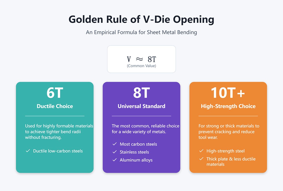
- Golden Rule (Empirical Formula):V = (6 ~ 10) × T, where V is the V-die opening width and T is the material thickness.
- 6T: Suitable for ductile low-carbon steels.
- 8T: The most common universal value, applicable to most carbon steels, stainless steels, and aluminum alloys.
- 10T (or even 12T): Recommended for high-strength steel, thick plate, or less ductile materials.
- Deeper Insight – This is more than a formula; it’s a conversation with the material:
- Too Narrow (V < 6T): A common and critical beginner mistake. An overly narrow opening forces the material to deform sharply over a tiny radius, causing exponential increases in bending force and extreme tensile stress along the outer surface—leading inevitably to cracks. It’s like trying to snap a thick stick over your knee instead of bending it gently across a wide support.
- Too Wide (V > 12T): Produces a large, hard-to-control bend radius and demands more punch travel. Worse yet, the sheet may slide along the die shoulders, severely compromising dimensional and angular precision.
- A Rule You Must Never Break: Always orient the bend line perpendicular to the material’s rolling grain. If bending parallel to the grain is unavoidable, ductility drops dramatically—so compensate by selecting a wider V-die opening (e.g., increase from 8T to 10T or 12T). This provides a gentler deformation zone, serving as your last defense against cracking.
3.2 Core Procedure Guide: Fine-Tuned Execution of Two-Step and Single-Step Methods
With the right tools and setup in place, it’s time to step onto the production battlefield—executing each move with exact precision.
3.2.1 Technique One: Two-Step Sequential Bending (First Bend Sets the Reference, Second Bend Ensures Parallelism)
This classic method achieves high-precision U-shaped bends using general-purpose dies, with its essence lying in precise reference control.
First Bend (Set the Reference):
- Operation: Firmly press the edge of the sheet against the backgauge and perform the first 90° bend (or with springback compensation).
- Key Point: The accuracy of this step defines everything. It simultaneously sets one leg of the U-channel and the reference for the bottom width. The backgauge accuracy directly determines the base width, while the bending angle precision here establishes the foundation for final parallelism.
Flipping and Positioning (The Critical Transition):
- Operation: Rotate the workpiece horizontally by 180°.
- Expert Tip: The second positioning must not rely on the raw edge of the sheet. Instead, it must use the inner wall of the first formed bend as the reference. Align the inner surface of the first bend snugly against the backgauge fingers before making the second bend. Only then will both legs of the U-channel be symmetrical about the base, fundamentally eliminating dimensional accumulation caused by shear inaccuracies.
Second Bend (Maintain Parallelism):
- Operation: Perform the second 90° bend (or with compensation as required).
- Key Point: The springback of this bend must match the first one exactly. Even minor angle discrepancies can be magnified by mechanical leverage, causing non-parallel legs that form an “A” or “V” shape. This is where CNC press brakes with angle-compensation databases and real-time angle measurement demonstrate their overwhelming advantage.
3.2.2 Technique Two: Single-Step U-Channel Forming (Dedicated Die Setup and Pressure Control)
This method prioritizes extreme efficiency and consistency, with its core principle being the precise coordination of die setup and pressure control.
1. Die Alignment: Centering the dedicated U-die is absolutely crucial. Use alignment tools or laser calibration to ensure the upper die (straight punch) and the lower die (U-groove) are perfectly aligned. Even a 0.1 mm misalignment can result in uneven wall thicknesses, angular deviations, or—in extreme cases—damage to costly tooling under high pressure.
2. Pressure Setting: Pressure control in one-step forming requires a delicate balance.
- Bottoming Bend: Apply sufficient pressure to fully seat the U-channel base against the lower die, effectively “ironing” the material to eliminate springback. An advanced technique is to monitor the change in the bottom radius—when further pressure no longer alters the radius, the optimal bottoming state has been reached.
- Dwell Time: Set a brief hold period of about 0.5–1 second. This gives the metal’s internal stresses a moment to stabilize and redistribute, effectively “locking in” the shape and minimizing springback.
3.2.3 Technique Three: Advanced Air Bending (Using Overbend to Compensate Springback)
This is the essence of modern CNC bending—it relies not on brute force but on precise control and intelligent use of material behavior.
1. Core Principle: In air bending, the final angle depends solely on the penetration depth of the punch (Y-axis travel). By allowing the punch to go slightly deeper—an overbend—you intentionally form an angle sharper than the target (e.g., 88°). When pressure is released, the material springs back to the desired 90° due to its inherent elasticity.
2. Refined Operation:
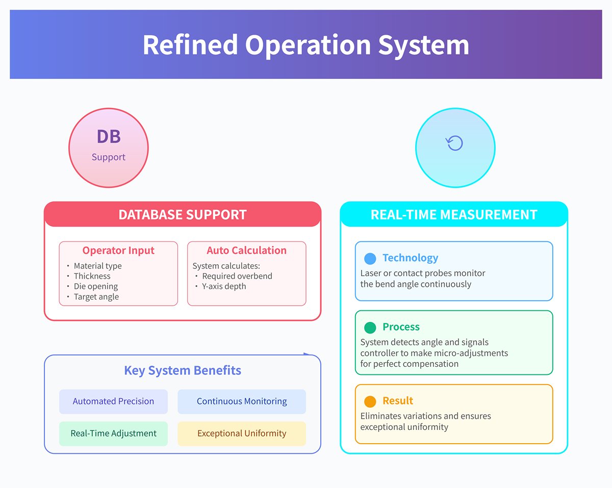
- Database Support: Modern CNC controllers are equipped with comprehensive material databases. The operator simply enters the material type, thickness, die opening, and target angle. The system then automatically calculates the required overbend degree and Y-axis travel depth using built-in algorithms and empirical data.
- Real-Time Angle Measurement System: This is the “autopilot” of U-bend precision. Laser or contact probes mounted on the press brake continuously monitor the bend angle. When the system detects that the current angle has reached, for example, 88.5°, it signals the controller to make micro-adjustments to the punch depth until perfect compensation is achieved. This technology virtually eliminates variations caused by batch differences, material thickness tolerance, or hardness inconsistency, ensuring exceptional uniformity across parts.
3.3 Equipment Calibration and Setup: The Critical Tuning for First-Time Success
Even the best technique demands precise equipment execution. The final pre-bending calibration is the ultimate safeguard for getting it right the first time.
3.3.1 Speed and Dwell Time: The Art of Optimizing Bending Speed and Hold Duration
Bending Speed: Faster isn’t always better. A professional sequence involves the punch descending rapidly (approach speed) and switching to a slow, controlled working speed just before contacting the workpiece. This “gentle touch” reduces impact, promotes even material flow, and results in more stable and consistent angles. For surface-sensitive materials such as stainless steel or aluminum alloys prone to cracking, slow bending is essential for maintaining quality.
- Dwell Time: As noted earlier, this is primarily applied in bottoming and coining operations. Setting a dwell time between 0.5–2 seconds is one of the most economical and effective ways to reduce springback.
3.3.2 Precision Alignment: Verifying Backgauge, Laser Guide, and Die Parallelism
Backgauge: This is the lifeline of dimensional accuracy. Regularly verify its X-axis (front–back), R-axis (up–down), and Z-axis (left–right) positioning accuracy using calibration blocks. Any wear or looseness must be corrected immediately.
- Die Parallelism and Deflection Compensation: Ensure that the upper and lower dies remain perfectly parallel along the entire working length. Because of the tremendous pressure involved, both the ram and bed may develop a slight concave “smile” deflection at the center, making the middle angle larger than the ends. To counter this, precisely adjust the crowning system, which applies a compensating upward force via hydraulic or mechanical means—balancing pressure and maintaining uniform angles throughout the work length.
3.4 Quality Inspection Checklist: A Quick Post-Bend Self-Assessment Guide
A flawlessly bent U-channel should demonstrate its quality at a glance—no need for complex instruments. Use the following checklist as your benchmark for evaluation:
☐ Angle Consistency: Use a high-precision protractor to verify that both bends measure 90° (or per design spec) and remain uniform throughout the entire length.
- ☐ Leg Parallelism: Use calipers to measure the width at both the opening and the base of the U-channel. The difference between these two measurements should fall within the specified tolerance, directly reflecting the degree of parallelism.
- ☐ Uniformity of Inner Radius: Visually inspect both inner radii to ensure they are identical in size, smoothly rounded, and free from abnormal compression or deformation.
- ☐ Surface Finish (Scratches and Indentations): Under a light source, carefully examine both the inner and outer surfaces of the U-channel—especially along the outer radius—for any galling or scratches caused by heavy friction with the die. Check the inner surface for any die marks.
- ☐ Leg Length and Base Dimension Tolerances: Use calipers or a height gauge to measure the length of both legs and the width of the base, ensuring they precisely fall within the tolerance range specified on the drawings.
Ⅳ. Advanced Strategies: Moving from Proficiency to Mastery
Achieving operational proficiency is only half the journey. True mastery lies in the ability to dynamically optimize based on varying conditions, unlocking the full potential of equipment, materials, and processes. This section focuses on strategies that elevate you from simply “getting the job done” to true expertise—from good to exceptional. It’s not just about refining techniques; it’s about evolving your mindset.
4.1 Material-Specific Playbook: Tackling the Bending Challenges of Different Metals
Every metal has its own "personality"—its unique mechanical properties. Understanding and respecting these traits is essential for mastering complex U-bends. A true master never forces all materials to conform to a single set of parameters, but instead works with them like a skilled animal trainer, guiding each one according to its nature.
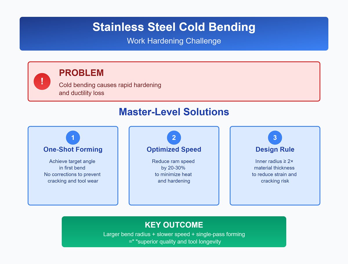
4.1.1 Stainless Steel: Managing High Springback and Work Hardening
Stainless steel—especially 300-series austenitic grades—is renowned for its corrosion resistance but dreaded by benders for two reasons: severe springback and pronounced work hardening.
- High Springback: Its springback can be two to three times that of mild carbon steel, making simple “overbending” compensation difficult to control with precision.
- Master-Level Solutions:
- Aggressive Die Angle Selection: If mild steel requires an 88° lower die for a 90° bend, stainless steel may call for an 85° or even 82° die to allow sufficient compensation for springback. Build and maintain an internal database based on hands-on experience.
- Ultimate Coining Application: For ultra-precise U-parts with ±0.2° tolerance, coining is the most effective way to eliminate springback. By applying 5–8 times the tonnage of air bending, you induce intense plastic deformation at the bend root, forcing the material to yield. This is a high-cost, high-accuracy, final-resort method.
- Extended Dwell Time: Adding a 1–2 second hold at the bottom of the bending stroke allows internal stresses to relax and redistribute, reducing springback by roughly 10–15%. This is a low-cost optimization trick.
- Master-Level Solutions:
- Work Hardening: During cold bending, stainless steel rapidly hardens, dramatically reducing ductility.
- Master-Level Solutions:
- One-Shot Forming—No Corrections: Achieve the target angle in the first bend. Any attempt to re-bend or correct will make the material extremely hard and brittle, prone to cracking, and will cause severe wear to costly tooling.
- Optimized Bending Speed: Use a slower ram speed. Excessive speed generates heat, which accelerates work hardening. Reducing speed by 20–30% often results in better quality bends.
- Design-Stage Radius Consideration: Where possible, specify the largest feasible inner bend radius for stainless steel U-bends. The golden rule: inner radius ≥ 2 × material thickness. This reduces strain in the bend area, lowering the risk of work hardening and cracking.
- Master-Level Solutions:
4.1.2 Aluminum Alloys: Minimum Bend Radius Guidelines to Prevent Cracking
Aluminum alloys—especially aerospace-grade high-strength types like 2024 and 7075—have far less ductility than steel, making them highly susceptible to micro-cracks or outright fracture on the outer bend radius.
- Minimum Bend Radius: This is the lifeline for aluminum U-bends. Ignoring it will almost certainly result in scrap.
- Master-Level Solutions:
- Treat the Material Manual as Law: Never guess the minimum bend radius for aluminum alloys. Always check and follow the specifications for the exact alloy and temper (e.g., -T3, -T6). A critical but often overlooked detail: minimum radius requirements are closely tied to the rolling grain direction. Bending perpendicular to the grain (“good” direction) allows a much smaller radius than bending parallel to the grain (“bad” direction)—sometimes the difference can be more than twofold.
- Use Polyurethane Protective Film: Line the shoulders of the lower V-die opening with a high-strength polyurethane film. This not only protects anodized or brushed aluminum surfaces but also acts as a cushion, distributing tensile stress more evenly across the outer layer, significantly reducing cracking risk when working near the minimum radius.
- Smart Use of Heat Treatment: For hard alloys like 7075, sometimes the only viable approach is localized annealing before bending, or forming in the “O” (fully annealed) condition followed by solution heat treatment and aging to restore final strength. This is a systemic, process-chain solution.
- Master-Level Solutions:
4.1.3 High-Strength Steels (HSLA / AHSS): Special Tooling and Tonnage Considerations
High-strength and advanced high-strength steels are widely used in automotive and other sectors for lightweighting, but their tensile strengths can be many times higher than mild steel, posing significant bending challenges.
- Exponential Tonnage Increase:
- Master-Level Solution: Never underestimate required tonnage. Using tonnage charts for mild steel is a common cause of press brake overload or tool damage. A practical rule: for every doubling of tensile strength, required bending tonnage roughly doubles. Always use tonnage calculators or charts specifically designed for high-strength steels.
- Tooling Survival Rules:
- Master-Level Solutions:
- Wider Lower Die Opening: Due to extreme springback, use a V-die opening significantly wider—typically 10–15 times material thickness, compared to 8× for mild steel—paired with a sharper punch angle to accommodate the large springback.
- Master-Level Solutions:
- Invest in higher-strength dies: Standard 42CrMo dies may crack or permanently deform under the immense pressure exerted by high-strength steel. It is essential to use specially heat-treated dies—such as those that have undergone induction hardening followed by tempering—that offer superior hardness (HRC 60+) and toughness. Reputable die suppliers will explicitly indicate whether their products are suitable for high-strength materials.
- Increase the punch radius: To prevent cracking, high-strength steels require a larger bending radius. Accordingly, the punch’s R angle must be enlarged to match. This consideration should be integrated early in the design stage.
4.2 Smart Technology Empowerment: Using CNC Systems for Exceptional Consistency
Modern CNC press brakes are not just powerhouses—they are intelligent systems. Mastering their “brains” is the key to elevating U-shaped bend precision and consistency to an entirely new level.
4.2.1 Angle Correction Database and Real-Time Compensation System
- Angle Correction Database: This functions as the press brake’s “experience memory bank.”
- Application: After an operator successfully bends a part for the first time, the precisely measured springback value can be stored in the controller’s database. When the same combination of material, thickness, and dies is used again, the system automatically calls up this data for pre-compensation—achieving stable, repeatable production on the first attempt.
- Master-Level Practice: Establish a dynamically updated internal “springback knowledge base” instead of relying on generic factory data. Create precise compensation entries for every frequently used material and batch. This approach allows even less experienced operators to produce high-precision parts, effectively transforming expert know-how into a digital enterprise asset.
- Real-Time Angle Compensation System: This is the “autopilot” for U-bend precision control.
- Application: Laser or contact probes installed on the press brake measure the bending angle in real time during the operation. Once the angle reaches the preset value, the measurement system sends the live data to the CNC controller, which uses built-in algorithms to calculate dynamically whether the ram should continue or stop—ensuring perfect final angles.
- Core Advantage: This system nearly eliminates inconsistencies caused by variations in sheet thickness or hardness—even across different areas of the same sheet—ensuring every product achieves exceptional uniformity. Such capability forms a cornerstone of Industry 4.0 manufacturing.

4.2.2 Offline Programming and 3D Simulation: Avoiding Collisions and Optimizing Sequences
- Application: Engineers can use identical software to that of the press brake controller on a computer in the office to import 3D models of the parts and perform virtual bending simulations.
- Avoiding Costly Collisions: The software automatically simulates the entire bending process, including flipping and repositioning the workpiece. If any flange of the U-shaped channel interferes with the press brake’s beam, backgauge, or dies, the software highlights the collision area in red. Engineers can then correct the design or process sequence beforehand, preventing equipment, tool, and part damage.
- Intelligent Sequence Optimization: For complex parts featuring multiple U-bends, the software’s algorithms can automatically determine the optimal bending sequence—minimizing flipping and movement, thus reducing non-productive time and significantly boosting efficiency.
4.3 Multiplying Production Efficiency: Optimization Beyond Basic Operation
Once precision is mastered, efficiency becomes the next battlefield.
4.3.1 Combining Quick-Change Die Systems and Multi-Station Bending
- Application: The combination of these two technologies provides outstanding flexibility and productivity, making it ideal for small-batch, multi-variety production environments.
- Scenario: Imagine a chassis panel requiring three different-sized U-shaped grooves. Traditionally, all parts would be bent for the first groove, followed by a full die change to start the second—resulting in significant downtime.
- Combined Power: By using hydraulic or pneumatic quick-change systems, all dies for the three U-shaped grooves can be set up simultaneously on the workbench in a multi-station layout. The operator simply moves the sheet between stations to complete all bends in a single setup—reducing die change time from tens of minutes to mere seconds. This transforms single-piece flow production into a highly efficient reality.
4.3.2 Robotic Automation Integration: From Loading to Bending Across the Entire Workflow
- Application: For high-volume, standardized U-bend production, automation is the ultimate solution to achieve optimal cost and efficiency.
- Process: Robots pick up sheets from the stack, position them with precision via a vision system, and feed them into the press brake. After bending, the robot retrieves, flips, or transfers the part to the next station. The entire process operates autonomously—enabling continuous 24-hour production.
- Master-Level Considerations: Successful robotic integration is far more than combining separate devices. The key lies in: 1. Gripper design—ensuring secure yet damage-free handling even at high speed; 2. Deep communication between robot and press brake control systems—for seamless coordination; and 3. Precise offline programming—simulating all movements within a virtual environment to identify and resolve potential interference and sequencing issues beforehand.
4.4 Die Life Management: Strategies for Extending Lifespan and Reducing Costs
Dies are high-value consumables. Professional management can save substantial hidden costs.
4.4.1 Best Practices for Lubrication, Maintenance, and Periodic Regrinding
- Lubrication: When bending high-strength or stainless steels, apply specialized extreme-pressure lubricants to the die shoulders. This significantly reduces friction, prevents material galling, and protects both the die and the workpiece surface.
- Maintenance: At the end of each workday, clean the dies with a soft cloth, remove any debris or chips, and apply a thin layer of anti-rust oil. Store unused dies on dedicated racks to avoid impact damage and corrosion.
- Regular Regrinding: Whenever die edges or shoulders show wear, have them professionally reground. An essential rule: both upper and lower dies must be reground simultaneously, and the amount of material removed must be equal on both sides; otherwise, press brake depth control and angle accuracy will be compromised, potentially ruining the entire die set.
4.4.2 Cost-Effectiveness Analysis of Die Materials and Coatings
- Die Materials:
- Standard Materials (e.g., 42CrMo): Ideal for most carbon steel and aluminum alloy bending applications, offering the best cost-performance ratio.
- Higher-Grade Tool Steels (e.g., Cr12MoV): Provide superior hardness and wear resistance, suitable for mass production or stainless steel bending.
- Special Powder Metallurgy Steels: Designed for advanced high-strength steel bending, delivering exceptional compressive strength and toughness. Although costly, they are the only viable choice for certain high-demand applications.
- Surface Coating:
- Nitriding Treatment: A cost-effective and efficient surface hardening process that significantly enhances wear resistance and corrosion protection.
- TiN / TiCN Coatings: These gold or blue-gray physical vapor deposition coatings feature extremely low friction and exceptionally high surface hardness. Perfect for bending stainless steel and aluminum alloys, they prevent scratching and material adhesion. Although coating involves an initial expense, the resulting mold life extension—typically three to five times longer—and improved product quality make it a profoundly worthwhile investment.
Ⅴ. Practical Application and Troubleshooting: From Case Studies to Problem Solving
Having knowledge is one thing; applying it skillfully in the heat of production is another. The true value of theory manifests only when it solves real-world problems. This chapter focuses on practical implementations, offering targeted solutions for specific scenarios, a rapid troubleshooting guide, and a cost decision framework. It culminates in a deep-dive case study that demonstrates the astonishing returns of systematic optimization—where theory meets reality on the production floor.
5.1 Scenario-Based Solutions: Best Practices Across Three Key Industries
U-shaped bends are everywhere, yet their requirements differ dramatically across industries. Mastery lies in tailoring optimal process combinations to each specific context, rather than relying on a one-size-fits-all formula.
5.1.1 Electronics Enclosures: Precision and Aesthetic Perfection
- Core Challenge: Products such as server chassis, communication equipment housings, and electrical control cabinets demand extremely tight U-slot dimensional consistency—typically within ±0.1 mm—to ensure modular assembly. Surface finish requirements are equally stringent; even minor scratches can compromise EMI shielding or lead customers to reject parts for cosmetic flaws.
- Best Practices:
- Mold Selection Protocol: The industry standard is single-step U-channel forming using dedicated U-shaped dies with TiN or TiCN coatings. These gold-colored PVD coatings provide exceptional hardness and ultra-low friction—like wrapping the tool surface in silk—eliminating scratch risks caused by friction.
- Dual Protection for the Lower Die: Even with coatings, top-grade finishes such as mirror-polished stainless steel or anodized aluminum require an impression-free protective film over the die shoulders. This seemingly simple layer is the final safeguard for high-value components.
- Ultimate Method for Springback Control: Use bottoming or mild coining, combined with a hold pressure (dwell time) of 0.5–1 second. By densifying the bend root under higher pressure, these approaches effectively eliminate most springback, guaranteeing uniform U-slot dimensions—ensuring inner rails or server modules slide in as smoothly as chocolate.
- A Master-Level Trick: Vent panel frames often suffer hole-spacing distortion before and after bending. The expert approach is to apply inverse deformation compensation during offline programming—intentionally offsetting hole positions by tenths of a millimeter on the flat layout. After bending and stress elongation, the final hole spacing precisely matches the design intent. This is predictive manufacturing at its finest.
5.1.2 Automotive Parts: Balancing Strength and Lightweight Design
- Core Challenge: U-shaped components such as chassis reinforcements, seat rails, and crash beams must be both strong and lightweight. They commonly use advanced high-strength steels (AHSS) and ultra-high-strength steels (UHSS), which behave like wild beasts during bending—exhibiting massive springback, high tonnage requirements, and crack risks.
- Best Practices:
- Synergy Between Tonnage and Deflection Compensation: Always calculate tonnage using specialized charts for high-strength steel and fully utilize the press brake’s hydraulic or mechanical deflection compensation system. Due to the broad contact area of U-bending, enormous forces can cause imperceptible “smile-shaped” deflection of the bed and ram. Only precise compensation ensures consistent angles across the full length, maintaining structural integrity.
- Mold Strategy for Survival: Employ V-dies with larger radii and wider openings—typically 10–15 times the sheet thickness, far above the usual 8× for mild steel—to relieve forming stress and prevent cracking. The dies themselves must be rated for high-strength materials, featuring superior compressive strength (often with laser marking indicating maximum permissible tonnage).
- Essential Real-Time Angle Control: Use an inline laser angle measurement system. High-strength steels can vary significantly in springback between batches or even across a single sheet. Fixed compensation no longer meets the automotive industry’s strict CPK (process capability) requirements. Real-time measurement and adaptive correction are indispensable for ensuring every part stays within tolerance.
5.1.3 HVAC and Construction: Managing Long U-Channel Bending and Distortion
- Core Challenge: Structures such as air ducts, cable trays, and curtain wall frames often use U-channels ranging from 3 to 4 meters long—or even longer. Extended lengths introduce major issues like twisting, warping, and the “banana bend” effect, where dimensions and angles differ between the middle and ends.
- Best Practices:
- Empowered Support Systems: Equip press brakes with front or rear sheet-following support arms. During bending and flipping, these arms actively hold the material, preventing sagging errors caused by self-weight and ensuring both dimensional accuracy and operational safety. For long U-channels, this is not a luxury—it’s mandatory.
- Art of Segmented and Symmetrical Bending: For extremely long parts, adopt segmented bending—starting with the center, then the ends, followed by full-length calibration. Alternatively, apply symmetrical bending around the center, alternating left and right sides to balance stress release and minimize overall distortion.
- Extreme Use of Deflection Compensation: With long U-channels, deflection compensation becomes critical. Without it, the middle angle will inevitably tighten compared to the ends, forming a “banana bend.” Operators should fine-tune the compensation curve based on test bends to achieve perfect straightness and uniform angular consistency along the entire part.
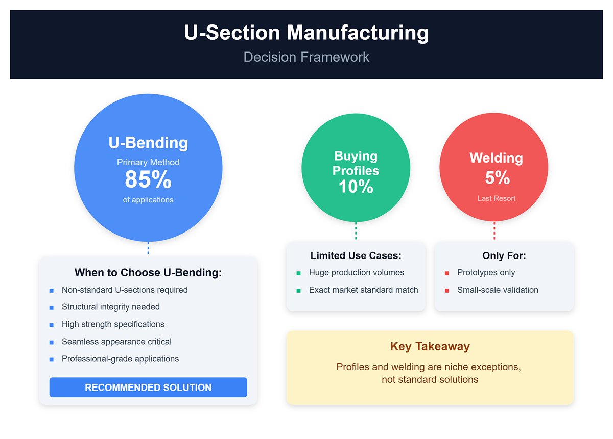
5.2 Cost Decision Framework: U-Bending vs. Welding vs. Buying Profiles
Choosing the right manufacturing method at the product design stage is the first step toward effective cost control.
| Manufacturing Method | Initial Investment | Unit Cost | Production Efficiency | Strength & Appearance | Suitable Scenarios |
|---|---|---|---|---|---|
| U-bending | Medium (tooling cost) | Low (material + electricity) | High (seconds per piece) | Excellent (one-piece forming, no welds, high strength, flawless appearance) | Non-standard dimensions/cross-sections, medium-to-large batch production, and applications requiring high overall strength and seamless finish (e.g., high-end equipment enclosures). |
| Welding into U-shape | Low (standard cutting/welding equipment) | High (labor + welding wire + post-processing) | Very low (minutes per piece) | Poor (welds are natural stress concentrators and corrosion points, with inferior appearance) | Prototyping, very small batches (a few pieces), or irregular geometries impossible to form in one bend. A compromise solution with lower quality. |
| Purchasing standard profiles | None (no tooling) | Market price dependent | Extremely high (cutting only) | Moderate (good strength but fixed dimensions; possible surface scratches) | Cross-sections matching market standard specs (e.g., national U-channel steel), no special size requirements, and very large demand volumes suitable for direct procurement. |
Core Decision Point: If your U-section is non-standard, or if you require structural integrity, high strength, and a seamless appearance, U-bending is almost always the only professional choice. Only consider buying profiles when production volumes are huge and the section exactly matches a market standard. Welding should remain the last-resort, lower-quality option, used only for prototypes and small-scale validation.
5.4 In-depth Case Study: How One Factory Cut U-Bend Scrap Rate from 12% to 2% through Process Optimization
Background: A factory producing server cabinets for data centers had a persistently high 12% scrap rate for its core load-bearing columns—complex cross-section U-shaped parts measuring 2.2 meters long, made from 1.5 mm galvanized steel. The main issues were inconsistent angles and non-parallel legs, which caused assembly problems for rails and server units, leading to costly rework and waste.
Optimization Journey:
- Step One: Abandon Guesswork, Trust the Data (Scrap rate reduced from 12% to 8%) The factory formed a process improvement team, whose first action was to scrap the old-timers’ “press a bit more by feel” compensation method. They purchased a batch of high-precision digital protractors and conducted systematic test bends for every material supplier and sheet thickness, recording exact springback values. These valuable data were then fed into the CNC press brake’s angle correction database. This single change cut their main scrap source—inconsistent angles—by more than half. Operators shifted from guesswork to precise execution.
- Step Two: Spotting the Invisible Deformation (Scrap Rate Reduced from 8% to 4%) While the angle issue had been addressed, problems like “banana bends” in long columns and non-parallel legs persisted. The team used a granite surface plate and a height gauge to precisely check the straightness of the columns after bending. They discovered that the deflection in the center of the 3‑meter work table under bending load deviated from theoretical calculations. Instead of replacing the machine, they invited the press brake manufacturer’s service engineer to recalibrate the hydraulic crowning compensation system. In addition, they installed a real-time laser angle measurement system. This system measured angles in segments during bending and dynamically instructed the crowning system to apply varying compensation forces at different positions. This “see and correct deformation in real time” approach virtually eliminated banana bends.
- Step Three: Tackling Issues at Both the Source and the Finish Line (Scrap Rate Reduced from 4% to 2%) The final 2% of scrap came from occasional surface scratches and positioning errors caused by sheet thickness variations.
- End-Point Optimization: All V‑dies used for processing the columns were given a TiN coating, and operators were required to apply a non-marring protective film before bending, eliminating surface quality defects.
- Source Optimization: They worked closely with their steel supplier to obtain coil stock with tighter thickness tolerances (improved from ±0.1mm to ±0.05mm). They also added a hardness spot-check step before materials entered the warehouse, keeping variability out of the shop floor.
Result: Through these three systematic optimization steps, the scrap rate for the U‑shaped load‑bearing column stabilized below 2%, saving more than 500,000 yuan annually in material and rework costs. More importantly, they established a data‑driven, continuously improving process control system—transforming U‑bending from a craft reliant on personal skill into a precise, controlled, and repeatable science.
VI. Conclusion
Our passage deeply talks about the various aspects of press brake u bend, ranging from technique details, practical guidance, and industrial application to future trends. To dive deeper into the technical specifications and see these technologies in action, you can explore our detailed brochures for comprehensive insights and product references. For tailored technical advice or professional consultation, feel free to contact us and our experts will assist you with customized solutions and recommendations.
VII. FAQs
1. Which type of press brake is most suitable for u bending?
The most suitable type of press brake for U-bending is a hydraulic press brake. Hydraulic press brakes offer superior precision, stability, and adjustability, which are essential for achieving accurate and consistent U-bends.
These machines can handle a wide range of material thicknesses and bending requirements, making them ideal for both high-precision and mass production U-bending tasks. Their ability to provide stable pressure ensures reliable results, especially when dealing with complex or repeated U-bending operations.
Additionally, hydraulic press brakes, particularly those with CNC integration, are well-suited for industries requiring high precision in U-bending.
2. What factors should be considered when selecting tooling for a press brake?
Choosing the right tooling involves assessing the material type, thickness, and required bend radius. Compatibility with the press brake's capacity and the need for specific bend shapes also play a role. Tooling material quality affects performance and longevity.
3. How can you increase the precision of bends when using a press brake?
Precision can be enhanced by ensuring proper alignment and calibration of the press brake. Using high-quality tooling and controlling the bending speed and force contributes to accurate results. Implementing gauging systems can further refine bend accuracy.
4. What safety precautions are necessary when operating a press brake?
Operators must use protective equipment and be trained in machine operation. Ensuring clear communication and establishing safety zones around the machine are vital. Machine guarding and emergency stop functions should be in place to prevent accidents.


