In modern metal fabrication, the Press Brake Automatic Backgauge has evolved from a simple mechanical stop into the intelligent heart of the machine. It is the core technology that underpins the speed, accuracy, and versatility of today's bending operations, enabling the creation of complex parts with micron-level precision.
This guide explores the full scope of this essential system. We will dissect its core principles and multi-axis strategies, offer a practical manual for shop-floor application, and look ahead to its future role in the smart factories of tomorrow. Join us to master the technology that transforms flat metal sheets into precision-engineered components.
I. Laying the Foundation: More Than Just a “Stopper”—The Engine Driving a Productivity Revolution
1.1 Core Definition: What Is an Automated Backgauge?
At its core, an automated backgauge is a high-precision mechatronic positioning system integrated into the rear work area of a press brake. It is powered by independent servo motors, driven through precision transmission mechanisms such as ball screws, and fully commanded by the CNC control system.
Its singular mission: to provide an absolutely precise, CNC-programmable physical reference for positioning metal sheets prior to bending.
The operating process is streamlined to perfection: operators no longer need to repeatedly measure with gauges or manually adjust stops. Instead, they input the target flange length into the CNC control panel, and the system reacts instantly. The backgauge fingers move at high speed and acceleration to the exact programmed position.
Once the sheet edge is gently pushed against the fingers, the bend line in the tooling is perfectly set. For complex workpieces with dozens of bends, the backgauge can reposition within milliseconds between bends, guiding the workpiece through the entire process with no manual intervention.
1.2 Value Leap: Why It’s the “Heart” of the Modern Press Brake
If the CNC control system is the press brake’s “brain,” thinking and issuing commands, then the automated backgauge is its “heart,” pumping efficiency, precision, and flexibility through the machine. Its role goes far beyond simple positioning—it is a revolutionary driver of exponential productivity gains.
- Exponential Efficiency Gains: This is its most visible advantage. It reduces the time cost of the most labor-intensive and error-prone step—manual positioning and adjustment—to nearly zero. In today’s manufacturing reality of “high mix, low volume,” changeover times drop from tens of minutes to seconds, dramatically boosting machine utilization.
- Micron-Level Accuracy and Absolute Consistency: Thanks to closed-loop servo control and precision ball screws, repeat positioning accuracy can consistently reach ±0.01 mm or better. This means from the very first to the ten-thousandth part, critical dimensions remain astonishingly consistent. Such unparalleled repeatability forms the backbone of high-quality modern manufacturing, eliminating scrap caused by human error.
- Unlocking Complex Workpiece Capabilities: Basic single-axis backgauges handle parallel bends, but modern multi-axis systems (such as X+R+Z1+Z2) open up the art of spatial bending. Fingers can move independently forward/back, up/down, and side-to-side, enabling easy handling of tapered parts, asymmetrical pieces, off-center bends, and varying flange heights on the same workpiece—processes once considered extremely challenging. This greatly expands design freedom and manufacturing possibilities.
- Lowering Skill Requirements and Improving Safety: Complex positioning calculations and tedious manual adjustments are fully handled by the CNC system and automated backgauge, drastically reducing reliance on operator experience. Even novices can produce quality parts after minimal training. Additionally, keeping hands away from the tooling area significantly improves production safety.
1.3 System Anatomy: A Visual Guide to the Inner Workings of an Automated Backgauge
To deliver such value, an automated backgauge relies on a coordinated set of precision components. Think of its structure through this analogy:
| Core Component | Analogy | Function & Core Value |
|---|---|---|
| CNC Control Unit | Intelligent Brain | Receives bending programs, calculates each axis’s motion path, speed, and end position, and issues commands. It is the system’s command center. |
| Servo Motors | Powerful Muscles | Provide precise, controllable drive for each motion axis. Built-in encoders feed back real-time position data for absolute accuracy. |
| Transmission Mechanism | Skeletal Tendons | Typically high-precision ball screws or timing belts; convert servo motor rotation into efficient, low-wear linear motion—critical for precision transfer. |
| Fingers/Stops | Dexterous Fingertips | The parts that directly contact the workpiece. Their material, shape, and adjustability (such as flipping or lifting) affect positioning stability and adaptability to different parts. |
| Multi-Axis System | Motor Nerves | Defines the backgauge’s range of motion. Common axes: X (fore/aft) sets flange length; R (up/down) adapts to different tool heights or clears formed flanges; Z (left/right) enables asymmetric positioning. Advanced systems feature independent X1/X2, Z1/Z2 axes for tapered bends. |
| Feedback System | Sensory Nerves | Encoders, linear scales, and other sensors continually monitor actual backgauge position, compare it to CNC commands, and implement closed-loop corrections in real time. |
| Mechanical Frame & Guide Rails | Sturdy Torso | Provides a rigid, stable mounting base. High-precision linear guides ensure smooth, straight movement of all axes—essential for long-term accuracy. |
II. Revealing the Core Principle: Where Does Micron-Level Precision Come From?

The automated backgauge’s astonishing micron-level precision is not the product of a single, mysterious high-tech part—it emerges from a flawless technological loop of control, drive, and feedback, continuously self-correcting. The philosophy at its core is an engineering truth: never blindly trust that a command was executed—measure, compare, and correct in real time until the target is incontrovertibly achieved.
2.1 Foundational Logic: The Infallible “Closed-Loop Control” System
The bedrock of the backgauge’s accuracy is Closed-Loop Servo Control. This technology eliminates the fatal flaw of traditional Open-Loop systems—the “fire and forget” mentality where success depends entirely on luck.
Let’s illustrate the fundamental difference with a vivid analogy:
- Open-Loop System: Imagine throwing a paper airplane toward a distant target with your eyes closed. You rely solely on experience to judge the force and angle, but once the plane leaves your hand, you have no idea where it will land—or whether it will veer off course—and you have no way to intervene.
- Closed-Loop System: Picture a modern guided missile. As it travels toward its target, onboard sensors scan the target's position thousands of times per second, constantly comparing it to the missile’s own location. The moment it detects even the slightest deviation from its intended path, the guidance system instantly adjusts the control surfaces to correct the course, ensuring a precise hit.
The closed-loop system for automated backgauge operates tirelessly on a millisecond scale, repeating this guidance logic over and over:
- Command: The CNC controller (the brain) issues an exact target position to the servo motor, for example: “Move to X-axis position 100.00 mm.”
- Execution: The servo motor (the muscles) receives the command, driving the precision ball screw to rapidly move the backgauge to the target position.
- Measurement: A high-precision encoder (the eyes), mounted on the motor shaft or directly on the moving part of the backgauge, measures its actual physical position in real time with exceptional resolution.
- Feedback: The encoder transmits this accurate position data back to the CNC controller at the speed of light.
- Correction: The controller instantly compares the “target position (100.00 mm)” with the “actual position (e.g., 99.98 mm).” If it detects even a 0.02 mm discrepancy, it immediately adjusts the servo motor’s command, increasing or decreasing torque to eliminate the gap.
This continuous command–execute–measure–feedback–correct loop ensures the backgauge position remains locked to the target value. Even slight resistance, vibration, or system inertia during operation is instantly compensated, delivering a positioning accuracy that virtually never fails.
2.2 Key Component Breakdown: The Three Pillars of Precision Transfer
Closed-loop control is the brain, but achieving ultimate accuracy depends on a mechanical “precision transfer chain” built from top-tier components. Three standout parts work in perfect harmony to turn digital commands into flawless physical positioning.
| Key Component | Role in the Precision Chain | Why It Matters |
|---|---|---|
| High-Resolution Encoder | "The precision ruler" and "the faithful messenger" | Acting as the eyes of the closed-loop system, the encoder’s resolution dictates the smallest movement the system can detect. It translates physical motion into digital language the CNC can interpret. Premium systems use absolute optical scale encoders that measure the backgauge’s linear displacement directly, with micron-level accuracy or better. This eliminates errors from mechanical play or elastic deformation in the drive train, forming the bedrock of ultimate precision. |
| Servo Motor | "Muscle that obeys instantly" | Unlike stepper motors, which move in fixed increments, servo motors are built to respond to feedback. They can finely adjust speed and torque in real time based on the controller’s commands. This means they can start and stop with lightning speed, then hold position with powerful stability against any disturbance, ensuring absolute reliability in positioning. |
| Precision-Ground Ball Screw | "The lossless drive skeleton" | This core component converts motor rotation into linear motion. Low-cost rolled screws suffer from backlash—small idle movement when reversing direction. High-end backgauges use precision-ground ball screws, whose raceways are meticulously machined and paired with preloaded twin-nut assemblies to achieve zero backlash. Every minute rotation of the servo motor is instantly and perfectly translated into linear movement without delay or loss. |
These three champions are inseparably linked, and it’s their seamless collaboration that forms an unbreakable precision transfer chain.
2.3 Common Misconceptions: Breaking the Operator’s Habitual Thinking
Even a backgauge system with micron-level accuracy doesn’t automatically guarantee perfectly precise parts. Operator habits and misunderstandings about system limits are often the main barriers preventing “theoretical precision” from becoming “real-world results.”
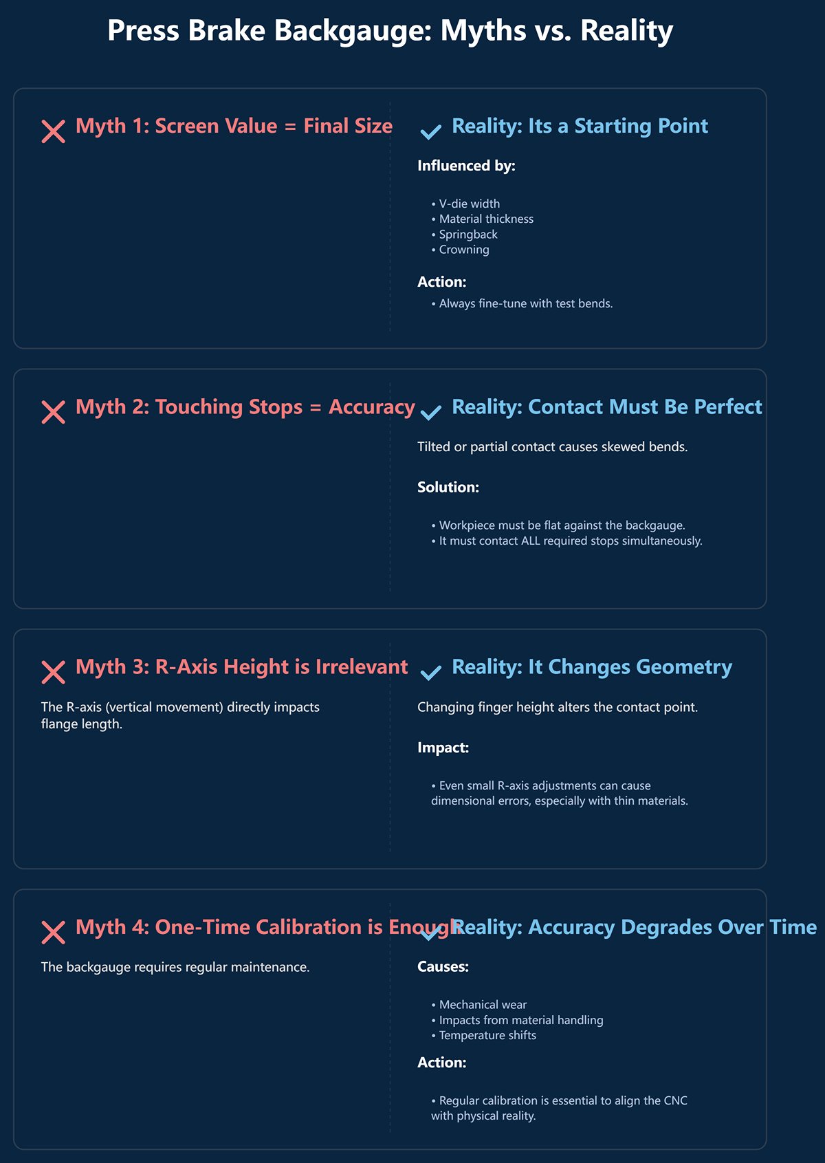
- Misconception 1: “The size shown on the screen is the final flange length.”
- Reality: This is the most common misunderstanding. The CNC display shows the theoretical positioning value of the backgauge fingers. The actual flange length is influenced by factors such as V-die width, material thickness, material springback, bending angle, and upper beam deflection (crowning compensation). Skilled operators know the backgauge value is a reference point that must be fine-tuned based on test bends, not a fixed, unquestionable truth.
- Misconception 2: “If the workpiece touches the finger stops, the position is accurate.”
- Reality: The contact method between the workpiece and the stops is critical. If the workpiece is tilted against one stop, or only contacts one of two stops, the bend line will skew, leading to dimensional and angular errors. The correct method: ensure the workpiece rests flat and contacts all required stops simultaneously—that’s the only way to achieve accurate positioning.
- Misconception 3: “The R-axis (vertical movement) of the backgauge has nothing to do with my bend dimensions.”
- Reality: This is a subtle yet dangerous misconception. Changing the backgauge finger height (R-axis) alters the contact point with the workpiece. That point’s geometric relationship to the V-die center directly affects the final flange length. When bending thin sheets or using small V-die openings, even a tiny R-axis change can cause visible dimensional deviations. The R-axis isn’t just for tool clearance—it’s a critical variable in bend dimension calculations.
- Misconception 4: “Once a new machine is factory-calibrated, it never needs recalibration.”
- Reality: The backgauge is a precision mechanical system subject to wear, accidental impacts, and temperature-induced shifts over time. Regular calibration is an essential maintenance step, not a one-time event. Calibration realigns the CNC’s digital world with the backgauge’s physical reality. Neglecting it is like asking a sniper with blurred vision to keep shooting—even with the finest rifle, accuracy will suffer.
III. Mastering Multi-Axis Coordination: Elevating Bending from 2D to 3D Art
If the closed-loop control system described earlier is the “physiological foundation” for precise automated backgauge positioning, then multi-axis coordination is its “soul,” enabling both technical mastery and artistic creation. Mastering multi-axis motion transforms the press brake from a tool confined to repetitive tasks on a flat plane into a digital sculpting platform capable of forming intricate three-dimensional components with precision.
Each additional axis opens an entirely new dimension of freedom in manufacturing, and their synchronized movements mark the pivotal leap from simple fabrication to intelligent manufacturing in modern sheet metal work.
3.1 Fundamental Dimension: X-Axis (Depth Control) – The Flange Size Determiner
The X-axis is the most basic and central coordinate in a backgauge system. It controls precise forward-and-back motion of the backgauge beam along a line perpendicular to the bend axis. Its position directly determines the final size of the flange after bending.
- Core Function: Any target flange length entered by the operator into the CNC system is first converted into an exact X-axis coordinate. The X-axis’s travel range, speed, and repeatability fundamentally define the maximum flange dimensions the press brake can produce.
- Expert Insight: Screen Value ≠ Final Size: This is the first dividing line between novices and seasoned professionals. The X-axis figure shown on the CNC display is not the actual finished flange length. It is a theoretical positioning point calculated by the control system using numerous variables—material thickness, tensile strength, V-die opening width, target bend radius, K-factor, and more. Advanced CNC systems leverage extensive material databases and sophisticated algorithms to pre-compensate for elongation and springback during bending. Thus, the true value of the X-axis lies not only in mechanical precision but in the “intelligence” of the control algorithms behind it.
- Advanced Application: Foundation for Conical Bending: When the system evolves to feature independent X1 and X2 axes, true three-dimensional shaping begins. By separately controlling the forward position of the left and right stops (X1 ≠ X2), the line between them can be set at a programmable angle to the bend axis. This is the prerequisite for producing conical components in a single forming process.
3.2 Agile Elevation: R-Axis (Height Control) – Intelligent Obstacle Avoidance and Support
The R-axis introduces vertical motion (up and down) to the backgauge system. Its purpose extends far beyond simply “avoiding obstacles”—it brings strategic intelligence to the bending process, playing a critical role when handling complex profiles and multiple bends.
- Core Functions:
- Smart Obstacle Avoidance & Die Adaptation: When a downward flange is already formed on the workpiece, the R-axis automatically raises to create a safe clearance path, preventing interference or collision. Similarly, when switching to dies of different heights, the R-axis adjusts automatically to the optimal support height—no manual intervention needed.
- Active Support & Stability: Large, thin sheets tend to sag under their own weight, causing positioning errors. In such cases, the R-axis can raise the stops to nearly level with the die, creating a solid, horizontal support surface that eliminates deformation-related inaccuracies.
- Little-Known Strategies:
- Ideal Partner for Z-Bends: In the second step of hemming or a Z-bend (flattening), the R-axis can descend in sync with the workpiece as the punch comes down. This dynamic, follow-along support prevents the piece from slipping or warping under high pressure, ensuring a clean, accurate flatten.
- Microsculpting Flange Dimensions: As noted earlier, changes in R-axis height subtly affect flange size. While the CNC system compensates automatically, elite technicians aiming for extreme precision will deliberately fine-tune R-axis height by ±0.1 mm to achieve nonlinear adjustments. This is a level of control beyond standard programming—an artisan’s “black magic.”
3.3 Tackling Asymmetry: Z-Axis (Lateral Control) – Unlocking Irregular Workpieces
The Z-axis governs the stops’ lateral (left-right) movement along the backgauge beam. When Z1 and Z2 can be programmed independently, it gives operators a near-universal key to handle almost any non-symmetrical or irregular workpiece.
- Core Function: By adjusting the spacing between Z1 and Z2, the system can accommodate workpieces ranging from extremely narrow to very wide, or place supports exactly where they’re most needed along the bend line.
- Three Key Scenarios for Irregular Parts:
- Non-Parallel Bends: When the bend line isn’t parallel to the sheet edge, one stop (e.g., Z1) can serve as a rotational pivot point while the other (Z2) is moved away. This allows the operator to rotate the workpiece freely, aligning scribed lines or features with the die for easy angled bending.
- Localized Support & Intelligent Clearance: For sheets with cutouts or protrusions, Z1 and Z2 can be positioned precisely on solid portions of the edge, avoiding the open areas entirely while maintaining stable, reliable positioning.
- Single-Side Positioning & Maximum Clearance: Some special shapes or very small workpieces require only one stop for positioning. Independent Z-axis control lets the program use only Z1 or Z2, moving the other completely out of the work zone to maximize space for flipping or maneuvering the part.
3.4 Coordinated Choreography: The Ultimate X+R+Z Strategy
The true value of multi-axis coordination lies not in simply combining individual axis functions, but in merging all degrees of freedom into a seamless, efficient, fully automated bending sequence—a CNC-orchestrated “choreography” executed with millisecond timing and micron-level precision.
The sole aim of this dance is to complete as many bends as possible in a single setup, pushing efficiency, accuracy, and manufacturing potential to their physical limits.
Real-World Scenario: Bending a Complex Tapered Chassis with Clearance Features
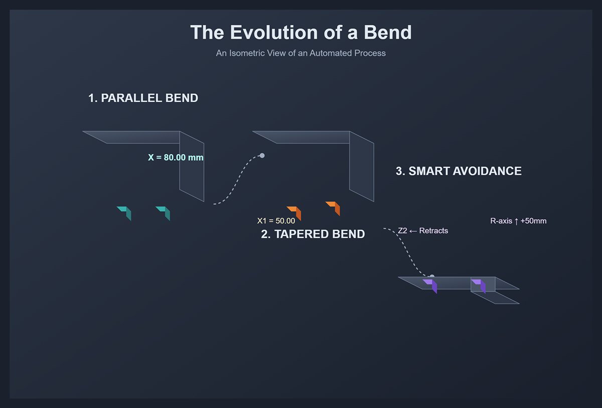
Picture the process flowing effortlessly:
- First Bend (90° Parallel Flange): The program starts. The X-axis snaps to 80.00 mm, the R-axis is at standard height, and Z1/Z2 automatically set to optimal spacing. The operator positions the sheet, presses the foot pedal, and the first bend is flawless.
- Second Bend (Tapered): The operator flips the workpiece. As he moves, the backgauge transforms: X1 positions at 50.00 mm, X2 at 45.00 mm, instantly creating a precise angle between the stops. The sheet is aligned again, and the tapered bend is executed smoothly.
- Third Bend (Smart Obstacle Avoidance): The workpiece is flipped again, with the previously formed flange facing downward. Now the backgauge’s intelligence shines: the R-axis automatically rises by 50 mm to provide generous clearance for the downward flange; simultaneously, Z2 retracts inward to avoid a side cutout. The X-axis moves to the next target dimension. The operator doesn’t need to think or adjust—he simply pushes the sheet against this “adaptive” reference, and the complex bend is completed.
In this "choreography of precision," every motion—from straightforward parallel positioning to tapered forming and intelligent obstacle avoidance—is executed automatically through the synchronized movements of the X, R, and Z axes under CNC command.
The operator’s role has evolved from a craftsman relying on experience, strength, and constant measurement into a modern technical expert who monitors and manages an automated process. This is the true power of multi-axis coordination in modern bending: the embodiment of human craftsmanship within the machine’s exact execution—creating continuously with near-perfect efficiency and zero error.
IV. From Programming to the First Qualified Part: The Operator’s Workshop Handbook
The depth of theory must ultimately be tested on the workshop floor. Transforming a two-dimensional drawing into a precise three-dimensional component requires the operator to translate a deep understanding of the backgauge system into a rigorous, meticulous, yet flexible workflow.
This journey—from “man-machine dialogue” to producing the first conforming part—is also the crucible through which a novice becomes a master. It tests not only the precision of the machine but also the operator’s intelligence and discipline.
4.1 Programming and Setup: Translating Drawings into Machine Movements
Programming is the first step in converting a designer’s intent into machine-executable instructions—and it often determines success or failure. Modern CNC systems have greatly simplified this process through intuitive graphical interfaces, yet the underlying principle remains unchanged: precisely defining the position and motion of the backgauge for every bend.
- Graphical Programming vs. Modal Programming: Two Main Approaches
- Graphical Programming: The most efficient and intuitive method. Advanced systems allow operators to directly import DXF (2D) or STEP (3D) models. The system automatically identifies bend lines and, drawing on its comprehensive database of materials and tooling, generates optimal bending sequences, interference-free motion paths, and all backgauge (X, R, Z) movements. The operator’s role shifts from “programmer” to “reviewer,” responsible mainly for verifying and fine-tuning the automatically generated plan.
- Modal Programming: A more fundamental and widely used approach. The operator manually enters key parameters for each bend according to the drawing directly on the CNC controller. This requires not only a thorough understanding of the drawing but also deep insight into bending processes. Typical inputs include:
- Bending Angle: For example, 90.0°.
- Flange Length: The core parameter for X-axis positioning and the most direct input value.
- Material & Thickness: Needed for the system to call up the correct bending force, compensation, and springback data.
- Punch & Die: The geometric parameters of the tools (V-opening width, shoulder radius, height) form the physical basis for all bending calculations—none can be omitted.
- Master-Level Insight: Harnessing “Virtual Bending” When dealing with unconventional bends or steps requiring precise positioning without actual deformation, a “0° bend” can be programmed. Under this command, the punch descends close to the sheet without contact, then retracts. Though no deformation occurs, the powerful multi-axis positioning capability of the backgauge can be used to move the workpiece precisely for marking, measurement, or as an intermediate reference for later complex setups. This decouples positioning from bending—a sophisticated technique and a secret weapon of top-tier technicians.
4.2 Calibration and Referencing: The “Sacred Ritual” of Every Startup
If programming sets the destination for the journey, calibration and referencing (Reference Search / Homing) ensure that your machine has an absolutely accurate GPS and starting point. Neglect this seemingly routine ritual, and even the most perfect program will rest on shifting sand.
- Homing: Awakening the Machine’s “Absolute Memory” Each time the press brake is powered on, the CNC system starts in a “memoryless” state—it has no awareness of the exact physical positions of the backgauge axes. Performing a “homing” or “reference search” instructs all axes (X, R, Z) to move slowly until their zero-point sensors (high-precision limit switches or encoder Z-pulses) are triggered. Only after this process does the CNC’s digital coordinate system align perfectly with the machine’s physical one, giving the displayed values true micrometer-level meaning.
- Backgauge Calibration: Reestablishing the “Contract Between Numbers and Reality” This is not a daily task, but it becomes essential when key components are replaced, unexpected collisions occur, or during quarterly preventive maintenance. Calibration’s essence is to redefine the precise geometric relationship between the CNC system and the bending line. Each step must be performed with absolute precision:
- Establish the Reference: Select a precise, intact, and representative punch-die pair, mount and align them securely. Prepare certified calibration blocks or gauge blocks.
- Physical Alignment: Gently lower the punch into the die so that the V-die centerline becomes a clear, indisputable physical reference—this is the “absolute zero” for all X-axis measurements.
- Calibrate the X-Axis: Command the backgauge to move to a known distance (e.g., 100.00 mm). Use a depth gauge or gauge blocks to measure the actual distance from the finger’s front face to the V-die center with precision.
- Enter the Compensation Value: Compare the physical measurement with the commanded value. The difference, however small, is entered as the X-axis compensation. It tells the system: “When you believe you’ve moved 100.00 mm, you’ve actually moved 99.98 mm—remember this in all future calculations.”
- Calibrate the R and Z Axes: Using the same logic, employ a level, square, and gauge blocks to ensure the R-axis moves vertically parallel to the machine frame and the Z-axis travels laterally parallel to the bending line.
- Core Misconception Clarified: Homing ≠ Calibration. Homing is the machine confirming “where am I?” each morning—an internal self-positioning process. Calibration, on the other hand, is like getting your eyes checked: ensuring the machine’s perception of the world remains accurate. Confusing the two is a key reason why precision quietly deteriorates over time.
4.3 Managing Variables: Dynamic Fine-Tuning of Material and Process
The first test bend is where theory collides with reality—and where an operator’s experience and intuition are truly tested. Even with the most advanced equipment, variations in material properties and subtle process changes demand surgical-level adjustment skills from the operator.
- Material Thickness and Hardness Variation Even within the same batch of metal sheets, thickness and hardness can fluctuate within the allowable tolerance range. For high-precision bending, a difference of just 0.05 mm can lead to noticeable deviations in angles and dimensions.
- Response Strategy: Never take material labels at face value. Before performing the first trial bend on a critical workpiece, use a micrometer to measure multiple points across the sheet, calculate the average, and manually input it into the CNC system. If hardness variation causes deviations in the first piece (for example, a nominal 90° bend results in 91°, indicating excessive springback), the operator should fine-tune the CNC’s “angle correction” or “X-axis compensation” parameters. Remember, the backgauge values serve as a baseline that must be refined based on real-world test results—they are a guide, not a gospel.
- The Hidden Influence of Grain Direction During rolling, metal sheets develop microscopic crystalline flow known as “grain.” Bending along the grain (with the grain) requires less force and behaves differently in springback compared to bending across the grain (against the grain).
- Little-Known Details: When bending U-shaped or polygonal box parts, if the four sides correspond to both with-grain and against-grain directions, even identical programming parameters will rarely yield a perfectly rectangular result. Corners may lose perpendicularity, and dimensions may drift. Expert operators anticipate this by setting small but crucial compensation values for each bend direction in the program (for example, increasing bend depth by 0.05 mm on against-grain sides) or by optimizing part layout on the sheet to ensure consistent grain orientation along all critical bend edges.
- The Subtle Role of Ambient Temperature Temperature fluctuations in the workshop can cause thermal expansion and contraction in the machine frame, guide rails, and hydraulic oil. These micron-level changes, amplified through mechanical transmission, can measurably affect backgauge positioning accuracy. Modern high-end press brakes often feature automatic temperature compensation systems. For standard machines, however, performing first-piece checks and minor adjustments at different times of day—such as early morning when the machine is cold and late afternoon after continuous operation—is a low-cost yet highly effective professional technique to maintain consistent accuracy throughout the day.
V. Embracing the Future: Intelligent Technology and Strategic Outlook
5.1 Cutting-Edge Technologies: Endowing the Backgauge with Perception and Thinking
The modern press brake backgauge has evolved into an intelligent, multi-sensory system, transcending its role as a simple positioning device. Vision systems provide an "eagle eye," using cameras to actively measure and correct sheet placement in real time, while integrated contact and force sensors offer a "sense of touch" to verify stable, gapless contact and eliminate dimensional errors.
For large or flexible materials, synchronized sheet support systems act as a "perfect partner," preventing sagging and deformation throughout the bending cycle. Crowning these advancements are AI-powered algorithms, which function as a "brain," leveraging machine learning and real-time data to predict material springback and proactively adjust parameters, moving the machine from merely executing commands to intelligently anticipating challenges for first-piece perfection.
5.2 Future Trends: Integration into the Smart Manufacturing Ecosystem
The future of automated backgauges lies in their evolution from standalone devices into integral execution nodes within a connected smart manufacturing ecosystem. Leveraging digital twin technology, engineers will simulate and optimize entire bending processes offline, sending validated programs directly to the machine to slash setup times.
Through bidirectional IoT communication with MES/ERP systems, backgauges will automatically execute production tasks derived from orders while feeding back real-time performance data for transparent factory management and predictive maintenance.
The pinnacle of this integration is the fully automated bending cell, where the backgauge functions as a critical positioning actuator in a "lights-out" factory, working seamlessly with robotics and vision systems to achieve continuous, unmanned production.
In essence, the press brake automatic backgauge is the definitive force behind modern metal forming. We've seen how its closed-loop precision, multi-axis agility, and disciplined calibration translate directly into superior parts.
Now, with the advent of AI and sensory feedback, this technology is evolving from a simple tool into an intelligent manufacturing asset. Embracing this evolution is key to maintaining a competitive edge. Ready to harness this power? ADH Machine Tool specializes in state-of-the-art press brake solutions designed for the modern fabricator.
Our advanced automatic backgauge systems can elevate your precision, accelerate your production, and prepare your facility for the future of smart manufacturing. You can also explore detailed product information and specifications through our Brochures to find the best fit for your production needs.
Contact us today to discover how our technology can revolutionize your workflow.


