I. Rethinking Maintenance: Why World-Class Maintenance Is a Profit Center, Not a Cost Center
In any factory that relies on metal forming, the press brake lies at the heart of value creation. Yet the maintenance surrounding it is too often misclassified as a mere “cost center” — an unavoidable expense to be minimized whenever possible. This is a dangerous and costly misconception. Exceptional maintenance is not an expense; it is a high-return strategic investment. It’s not about “spending money,” but about systematically “making money.” To understand this, we must first do the math and identify the three hidden costs that managers often overlook — the silent profit drainers that quietly erode the bottom line.
1.1 Counting the Real Costs: The Hidden Price of Downtime, Scrap, and Safety Incidents
Excellence in maintenance starts with a clear understanding of true cost. In most manufacturers’ financial statements, the real impact of equipment downtime, scrap, and safety incidents is grossly underestimated. These costs are like the submerged part of an iceberg — invisible at first glance, yet fully capable of sinking a company’s profitability.
- Downtime: The Costly Black Hole
An unexpected press brake shutdown costs far more than a few hours of lost production. It triggers a chain reaction: delayed orders and shaken customer trust; hefty overtime and expedited shipping charges to make up for lost time; and ongoing wages and depreciation expenses as skilled operators and valuable machines sit idle. For small and medium-sized companies, every unplanned stoppage bleeds cash, turning potential profit directly into loss. - Scrap and Rework: The Silent Profit Killers
When poor maintenance leads to reduced precision, scrap and rework start piling up. The real cost goes far beyond wasted materials. Hidden within it are “shadow costs”: transportation and handling of defective items, the valuable machine time and labor consumed by rework, the tied-up inventory from over-purchasing raw materials to offset higher scrap rates, and the testing and recalibration resources needed to fix defects. Combined, these quietly erode margins by several percentage points—enough to decide survival in a fiercely competitive market. - Safety Incidents: The Unbearable Price Tag
Among the three, this is the most devastating—and the easiest to ignore. A single safety incident caused by neglected maintenance can be catastrophic. The direct costs—medical compensation and regulatory fines—are only the beginning. Indirect costs, typically several times higher, include management time lost to investigations, replacement and training expenses for new staff, the repair or replacement of damaged equipment, and a collapse in morale that cripples productivity. Safety is the foundation of operations, and reliable maintenance is the cornerstone that upholds it.
1.2 ROI Breakdown: How One Hour of Proactive Maintenance Each Week Can Save Tens of Thousands Annually
Once we recognize these hidden costs, viewing maintenance as an investment becomes self-evident. Research shows that preventive maintenance (PM) delivers a staggering return on investment (ROI) of up to 545%. In other words, for every dollar spent on maintenance, you gain more than five in overall benefit.
So where does this return come from?
- Sharp Reduction in Downtime: Proactive maintenance eliminates over 80% of equipment failures, directly recovering lost production time.
- Lower Repair Costs: Replacing a small seal worth a few dollars is far cheaper than emergency repairs on a hydraulic pump worth tens of thousands. Overall maintenance costs can be reduced by 12–18%.
- Extended Asset Lifespan: A well-maintained press brake can easily operate 20–40% longer, yielding a longer value-creation cycle and a higher asset retention rate.
Let’s run a simple calculation. Suppose a workshop’s overall operating cost (including depreciation, labor, and utilities) is $500 per hour. By dedicating just one hour per week to scheduled proactive maintenance, the company prevents a major breakdown that would otherwise require a full workday (8 hours) to fix. The cost-benefit ratio would be:
- Investment: 1 hour × $500/hour = $500
- Return (Losses Avoided): 8 hours × $500/hour = $4,000
- Single-Event ROI: [(4,000 − 500) / 500] × 100% = 700%
This calculation doesn’t even factor in the preserved order profits, the waste reduction savings, or the brand reputation protected through consistent delivery. Investing just one hour per week can easily save tens of thousands annually in both direct and indirect costs.

1.3 Strategic Shift: From Reactive Fixes to Proactive Prevention
The traditional approach—“repair after failure,” or reactive maintenance—is the definition of passive management. It may appear cost-free upfront but actually represents high risk and high expense. Each breakdown becomes an emergency, bringing production halts, missed deadlines, and the chaos of last-minute, premium-priced repairs.
Modern asset management calls for a transformational shift—moving from “firefighting” to “fire prevention,” or proactive maintenance. The goal is to build a systematic, standardized process that eliminates issues before they occur. This transformation is not merely technical—it’s managerial. It means shifting the focus from “managing problems” to “managing health,” from patching leaks to preventing floods. To succeed, leaders must resist the lure of short-term savings and instead invest in long-term, stable, and predictable productivity—the foundation of sustainable competitive advantage.
1.4 Redefining the Operator: From Machine User to First Line of Asset Defense
At the heart of this shift is a redefinition of the operator’s role. Operators should no longer be seen merely as button-pushers. They must be empowered and trained to become guardians of machine health—the first line of defense in preserving asset value.
The central principle here is “I operate, therefore I maintain.” It replaces the old mindset of “I operate, you repair.” Operators spend every shift with their machines; they know the equipment’s “personality” best and can spot early warning signs—an odd noise, a puff of smoke, a drop of oil—that signal an impending issue.
By integrating operators into the maintenance system and giving them responsibility for daily tasks such as cleaning, inspection, lubrication, and tightening, companies unlock three key benefits:
- Dramatically improved early fault detection, stopping major breakdowns before they take root.
- A stronger sense of ownership among operators, greatly reducing wear caused by rough handling or negligence.
- Greater efficiency for maintenance specialists, freeing them to focus on preventive upkeep and technical optimization.
This is a genuine win-win: the company achieves higher Overall Equipment Effectiveness (OEE) and lower operational risk, while operators upgrade their own skills—evolving from simple manual laborers into highly valued technical professionals. Cognitive transformation begins on the front line and is solidified through systemic reinforcement.
2. System Anatomy: Gaining a Deeper Understanding of the Core Components of a Press Brake
To elevate maintenance from a repetitive chore into a value-creating craft, we must go beyond merely following the manual and instead grasp the machine’s internal mechanics and functional logic. A press brake is not a cold mass of steel—it is a finely tuned organism composed of five interdependent core systems. Only by understanding its “physiology” can we maintain it effectively. In the sections that follow, we will take an anatomical approach, examining each of these five systems in turn to uncover the science that drives optimal maintenance.
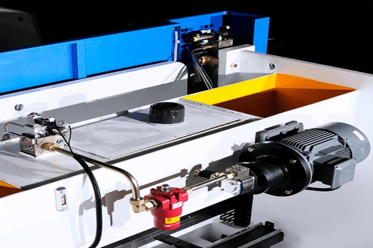
2.1 Hydraulic System: The Machine’s “Heart” (Pump, Valves, Hoses, Hydraulic Oil)
The hydraulic system is the driving force behind the press brake, converting electrical energy into hydraulic power to move the ram with precision. It serves as the machine’s “heart,” while the hydraulic oil is its “blood,” transporting energy and information throughout the system. Maintaining this heart’s health hinges on keeping its “blood” absolutely clean and stable.
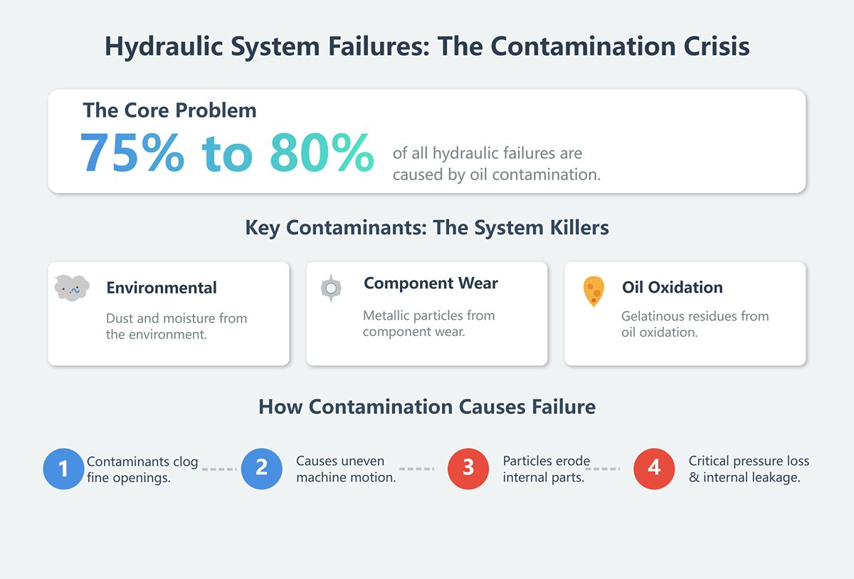
- Hydraulic Oil: More Than Just Lubricant—It’s the Carrier of System Health Data It’s time to rethink what hydraulic oil does. Beyond transmitting power, it also lubricates, cools, and protects against corrosion. Yet, a startling fact often overlooked is that 75% to 80% of hydraulic failures worldwide are caused by oil contamination. Microscopic impurities—whether dust and moisture from the environment, metallic particles from component wear, or gelatinous residues from oil oxidation—are the system’s “blood clots.” They can clog the fine openings of servo valves, causing delayed or uneven motion, and act like abrasive sandpaper, eroding pump vanes and cylinder walls, leading to pressure loss and internal leakage.
- The Essence of Maintenance: Shifting from “Scheduled Oil Changes” to “Condition-Based Oil Changes” The old rule of thumb—changing hydraulic oil every 6,000 hours—is neither economical nor scientific. The modern approach relies on Oil Analysis, essentially a “blood test” for the machine. By taking periodic samples and having them spectrographically analyzed, we can track key indicators such as cleanliness level (NAS/ISO class), viscosity, water content, and trace metal composition. The benefits are game-changing: this enables condition-based oil changes, avoiding premature replacement of healthy oil and the risks of running degraded oil too long. More importantly, analyzing abnormal increases in specific metal elements (like copper, iron, or aluminum) allows us—like a skilled physician—to predict which component (such as a copper-plated piston shoe, steel bearing, or gear) is beginning to wear abnormally. This transforms maintenance from reactive “damage control” into proactive “predictive health management.”
- Key Details Not to Be Overlooked:
- Temperature Control: Hydraulic oil performs best between 45°C and 50°C. Sustained temperatures above 60°C rapidly accelerate oxidation, causing darkened oil, viscosity loss, hardened seals, and greater leakage risks. Regularly clean the coolers and fins to maintain efficient heat dissipation.
- Filters: Acting as the system’s “kidneys,” filters must have their elements replaced regularly. A best practice is to carefully cut open the old filter and inspect the mesh for shiny metal flakes—one of the most direct indicators of internal wear.
- Hydraulic Lines: Conduct regular visual inspections, especially at bends and joints, to check for aging cracks or abnormal swelling. A minor leak can escalate into a burst hose under high pressure with catastrophic results.
2.2 Mechanical Structure: The “Skeleton” Ensuring Rigidity and Consistent Precision (Frame, Ram, Worktable)
The frame, ram, and worktable form the press brake’s “skeleton.” Their rigidity and assembly accuracy are the physical foundation for achieving consistent bending angles across the full length. The essence of structural maintenance lies in combating its greatest enemy—deformation.
- Frame and Deflection Compensation: The Art of Controlling “Breathing” Under full load, the press brake’s frame—especially around the throat—experiences micron-level elastic deformation, known as the machine’s “breathing.” This causes the distance between the ram and worktable to slightly expand in the center, resulting in larger bend angles there than at the ends. To counteract this, modern press brakes use hydraulic or mechanical crowning systems that apply a controlled counterforce beneath the worktable. Effective maintenance ensures this system remains precise and responsive. Yet, a more fundamental but often overlooked prerequisite is perfect machine leveling. An uneven floor subjects the frame to long-term torsional stress, not only disrupting crowning accuracy but eventually causing permanent structural distortion that ruins machine precision. Therefore, performing annual level checks and adjustments with a precision level is a highly cost-effective investment.
- Ram and Guideways: The Right Way to Lubricate The ram glides rapidly along the frame’s guideways—a critical zone for transmitting precision. The key to maintaining smooth, accurate movement is meticulous lubrication and cleanliness. Always follow manufacturer recommendations for lubrication intervals and grease type. A common but harmful mistake is applying new grease over dirty old grease. Contaminated lubricant, full of metallic dust, turns into an abrasive paste that gradually grinds down guideways and ball screws. The professional approach is simple: before adding new grease, thoroughly wipe away all old lubricant with a clean cloth. This small step can multiply the lifespan of moving components.
2.3 Tooling System: The “Teeth” That Define Bending Quality (Punches and Dies)
If the hydraulic system is the heart and the structure is the skeleton, then the tooling is the “teeth” that directly engage the workpiece to shape the final form. Even a micron-level change in tool condition can have a magnified impact on product quality.
- Wear: The Invisible “Angle Killer”
Tool wear is gradual and often uneven, making it easy to overlook. Rounding at the punch tip or indentation at the die shoulders increases the bend radius, forcing the operator to bend deeper to achieve the desired angle—disrupting angle linearity and program accuracy. We must develop a new mindset: attention to tooling shouldn’t wait until defects appear. Cleaning and inspection should be part of every tool change or end-of-day routine. - Use a magnifying glass and bright flashlight to examine the cutting edges, watching for even the smallest chips, scratches, or impressions, and periodically verify critical dimensions with precision gauges.
- Storage and Management: Professionalism Lies in the Details
Carelessly stacking precision-ground tooling in a metal cabinet is one of the leading causes of premature damage. The impact between cutting edges is far more destructive than most imagine. The professional approach is to use dedicated die racks, placing each die segment vertically or horizontally in an individual slot with protective padding, while periodically applying rust-prevention oil. A more advanced practice is paired management of segmented dies. Each die set leaves the factory with precisely matched segment heights. Mixing segments from different sets will cause height variations along the bending line, leading to angle deviations. Assign a unique matching number to every die set and ensure it’s always stored and used together—this seemingly small habit is the mark of true professionalism.
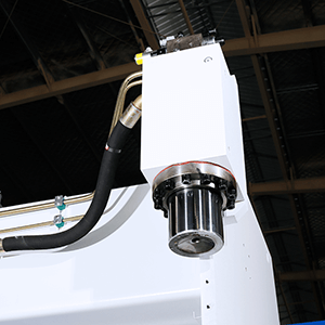
2.4 Backgauge and Control System: The “Brain” of Precision Positioning (CNC, Servo Motors, Sensors)
The CNC control unit and the servo-driven backgauge system together form the machine’s “brain” and “nervous system.” The brain issues commands, and the nerves execute them with precision—together they determine the dimensional accuracy of each bent part.
- Backgauge: Precision Begins with Absolute Cleanliness The repeatable accuracy of the backgauge positioning directly defines flange dimensional tolerance. Its drive elements—whether ball screws or synchronous timing belts—are high-precision components highly sensitive to dust and debris. The golden rule of maintenance: keep it impeccably clean. Any buildup of metal dust on the guides or screw can hinder smooth movement or even seize the system. Excess lubricant acts like flypaper, trapping contaminants and accelerating wear. Regularly clean with a lint-free cloth and compressed air. Each month, use calibrated calipers or gauge blocks to compare the backgauge’s actual position with the CNC display value, adjusting parameters when necessary.
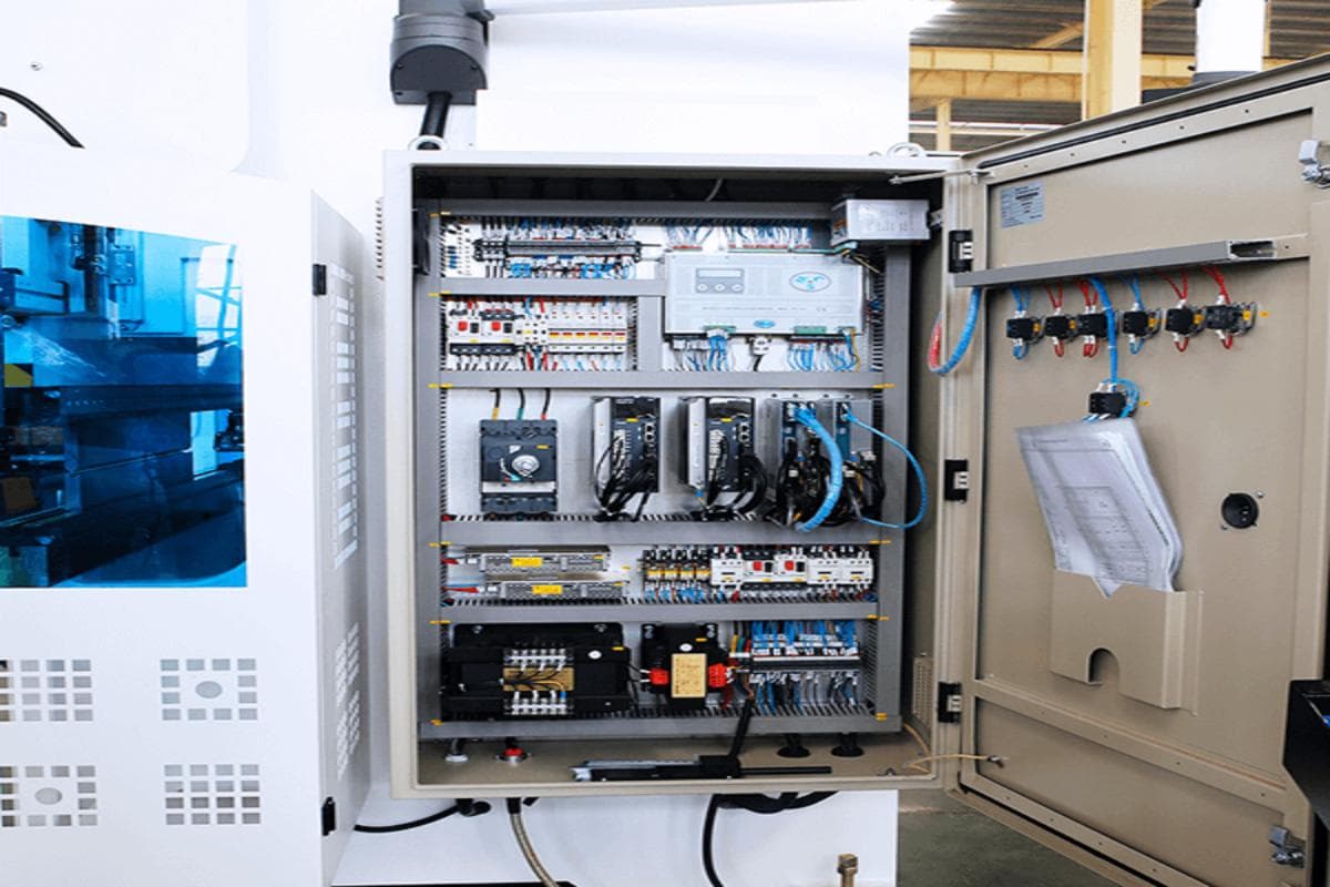
- CNC and Electrical System: Stability Above All Else For the CNC system—the “brain” of the press brake—the key to reliability is maintaining a stable, cool, and clean environment. Regularly clean dust filters on the electrical cabinet and verify that cooling fans are functioning properly to prevent heat-induced failures of electronic components. An often-overlooked “hidden threat” is power quality. Voltage spikes and harmonic distortions can trigger system freezes and data loss. Equipping precision press brakes with a dedicated industrial-grade Automatic Voltage Regulator (AVR) is an investment that pays dividends in uptime and reliability.
2.5 Safety System: The Non‑Negotiable Lifeline (Light Curtain, Emergency Stop, Foot Switch)
Among all systems, the safety system holds the highest priority. It exists not merely to satisfy regulatory requirements but as the operator’s true “lifeline.” Any compromise here is a direct disregard for human safety.
- Laser or Photoelectric Guards (Light Curtain): The Daily “Life Check” The light curtain is the core safety barrier preventing hand injuries. Its maintenance rule is absolute: conduct a full function test before the first operation of every day. This is not a symbolic ritual—it’s a lifesaving procedure. Operators must use the manufacturer’s standard test rod, simulating a finger, to block the upper, middle, and lower zones of the curtain one by one, verifying that the ram immediately stops and retracts when the beam is interrupted. Ensure that the curtain’s installation maintains the required safety distance from the die’s danger zone, in compliance with international or national standards (such as OSHA or EN ISO 13855), preventing operators from reaching into the hazardous area.
- Two-Hand Buttons, Emergency Stops, and Foot Switches: Ever‑Ready Guardians Whether it’s dual-hand operation buttons, red emergency-stop buttons scattered across the machine frame, or foot switches protected by safety covers, all must remain mechanically sound and electrically responsive. They represent the final line of defense in an emergency. Establish a zero-tolerance culture: under no circumstance—convenience, time pressure, or otherwise—should any safety device be bypassed, disabled, or removed. Maintenance of the safety system reflects not just technical discipline but an organization’s entire safety culture and core values.
3. Field Handbook: Multi‑Cycle Maintenance Checklists and Action Plans Ready for Immediate Use
Theory finds its true worth only when it guides practical action. This chapter transforms the preceding maintenance philosophy and system understanding into a concrete, measurable, and executable plan. It is not a rigid set of rules but a dynamic playbook designed to integrate maintenance seamlessly into daily operations—from the operator’s 5‑minute pre‑shift inspection to annual overhauls—building layer upon layer a robust “immune system” for the equipment.
3.1 Daily “Pre‑Flight” Inspection (5‑Minute Operator Check)
This is not an extra burden—it’s a ritual essential for safe and efficient production. Much like a pilot’s pre‑flight walk‑around, it quickly uncovers obvious abnormalities, safeguarding both safety and productivity for the shift ahead. It marks the operator’s transformation from a mere “user” to a true “guardian” of the machine.
3.1.1 Visual Inspection: Check for Leaks or Loose Connections
- Execution: Walk around the machine, scanning as if with a visual scanner—the floor, cylinder seals, hydraulic valve blocks, and every oil and air line connector. Lightly touch critical bolts to detect any looseness by feel.
- Deep Insight: Remember—every drop of oil on the floor tells a story. Learn to interpret it: a light-yellow, free-flowing leak points to hydraulic fluid; darker, more viscous traces may indicate slideway lubrication oil. The exact location of the stain enables you, like a detective, to quickly pinpoint the source. This is more than a check—it’s a daily “snapshot diagnosis” of the machine’s health.
3.1.2 Functional Test: Verify Light Curtain, Emergency Stops, and Foot Switches
- Execution:
- Start the machine and, using only the manufacturer’s standard test rod (never your hand or arm), block the upper, middle, and lower sections of the light curtain to confirm the ram halts instantly and retracts upon signal interruption.
- Press each red emergency-stop button on the machine to ensure power is completely cut off and cannot be restored until the stop is manually reset.
- Test the foot switch to verify responsive start‑stop action and confirm that its protective cover is intact and undamaged.
- Deep Insight: This test is not about ticking a compliance box—it’s a daily pact of trust between you and this powerful machine. Any malfunction breaks that pact, and the equipment must be treated as “grounded” until repaired. Turning this process into muscle memory is the most direct and effective investment in your own safety.
3.1.3 Cleaning and Lubrication: Remove Debris and Inspect Key Lubrication Points
- Execution: Use an industrial vacuum or lint‑free soft cloth to thoroughly remove all metal chips and dust from the worktable, tool slots, and backgauge guides. Visually confirm that the automatic lubrication system’s oil level is within the normal range.
- Deep Insight: A hallmark of manufacturing excellence is the belief that cleaning is inspection (Seisou wa tenken nari). As you wipe the guides, your fingertips can detect burrs or scratches that eyes might miss. Removing seemingly trivial metal debris in time prevents it from being drawn into moving parts, avoiding the potentially catastrophic “secondary damage” it could cause.
3.1.4 Status Verification: Check Tool Installation Security and Back Gauge Homing Function
- Execution: Visually inspect and gently push the upper and lower dies with a gloved hand to ensure they are firmly secured in the clamps without any play. On the control panel, run a full “home” cycle for the back gauge, observing its motion for smoothness and listening for any unusual noises. Confirm that it returns precisely to its programmed zero position.
- Deep Insight: When the back gauge fails to return to zero, beginners tend to blame sensors or motors. Seasoned technicians, however, know that in about 80% of cases, the root cause lies elsewhere—tiny obstructions on the guide rails or poor lubrication causing slight sticking. This simple homing check, performed before operation, can reveal and eliminate hidden alignment issues at no cost.
3.2 Weekly “Deep Health Check” (30-Minute Technician Inspection)
This procedure, led by a team leader or technician, goes beyond basic visual and tactile checks. It introduces preliminary quantification of core performance metrics, aiming to detect early-stage defects before they escalate.
3.2.1 Hydraulic System: Inspect Oil Level, Temperature, and Cleanliness
- Execution: When the machine is cold, check the hydraulic oil tank level to ensure it sits between the mid and upper marks on the gauge. After running the machine for 15–20 minutes, measure oil temperature via the control panel or an infrared thermometer—it should remain below 60°C. Through the sight glass or sample port, confirm that the oil is clear and free of emulsion (milky color) or excessive foaming.
- Deep Insight: A milky appearance in the oil signals water contamination, which drastically reduces lubrication performance and can corrode precision components. Persistently high oil temperatures often point to blocked cooling fins or internal leakage in the hydraulic pump—both red flags indicating the system is “overheating.”
3.2.2 Mechanical Components: Lubrication and Wear Check of Key Guide Rails and Ball Screws
- Execution: Thoroughly clean the slider guide rails, back gauge ball screws, and linear guides. Then, use the automatic lubrication system or apply the specified lubricant manually. Run a clean finger (or wear a thin glove) along the rail in its motion direction to feel for scratches, dents, or irregular wear.
- Deep Insight: The golden rule of lubrication is “thin and even.” A common but critical mistake is over-lubrication, assuming “more is better.” In reality, excess grease acts like a magnet for dust and metal particles, creating a destructive “grinding paste” that exponentially accelerates wear on precision components.
3.2.3 Accuracy Testing: Preliminary Check of Back Gauge Repeatability and Ram Parallelism
- Execution: Mount a dial indicator on a magnetic base or use a calibrated digital caliper. Command the back gauge to move repeatedly between several fixed points (at least five cycles), then measure positional consistency. The ideal tolerance should be within ±0.03 mm.
- Deep Insight: A simple yet effective method for checking ram parallelism—a “veteran’s trick”—is to place two precision blocks of equal height near the left and right frame ends of the table. Lower the ram slowly until it lightly presses both blocks. Then use a feeler gauge to test the gap between the ram and each block. Under ideal conditions, the same thickness gauge will fit on both sides—or the difference should be minimal.
3.2.4 Tooling Inspection: Detailed Assessment of Upper and Lower Die Edge Wear and Chipping
- Execution: Dismount one or more of the most frequently used die sets. Clean them thoroughly with an appropriate solvent, then, under adequate lighting, use a 5x–10x magnifier to examine the upper die tip and the shoulders of the lower die’s V-groove. Look for micro-chipping, dents, or rounding of edges.
- Deep Insight: Tool wear is notoriously “contagious.” When one section of a die is badly worn, operators instinctively increase overall bending pressure or penetration depth to compensate. This not only produces inconsistent bend angles but also accelerates wear in otherwise healthy die segments and strains the machine’s deflection compensation system.
3.3 Monthly / Quarterly Preventive Maintenance (PM Program)
These planned, proactive maintenance actions are designed to “defuse” potential failures before they occur—by replacing consumables, performing deep cleaning, and recalibrating key parameters.
3.3.1 Filter Replacement: Hydraulic Oil and Air Filters
- Execution: Follow the manufacturer’s recommended intervals (or use oil condition monitoring results) to replace high-pressure, return, and suction filter elements. At the same time, clean or replace the dust filters in the electrical cabinet and hydraulic station.
- Deep Insight: Never dispose of old filters without inspection. Cut them open carefully and spread the media on white paper—it’s an inexpensive internal reconnaissance method. Finding shiny copper or steel particles indicates severe wear in internal parts such as pumps or bearings. That discovery is an early warning of immense value.
3.3.2 Electrical System: Tighten Connections and Clean Cabinets and Cooling Fans
- Execution: (Warning: This procedure must only be performed by a qualified electrician after complete power-off and lockout/tagout!) Open the control cabinet and, using an insulated torque wrench, retighten all high-power connections, contactors, and circuit breaker terminals according to the torque values listed in the electrical schematic. Use a vacuum or low-pressure dry compressed air to remove all dust inside, paying close attention to cooling fans on the CPU, drives, and power modules.
- Deep Insight: An astonishing industry statistic shows that over 70% of electrical failures stem not from component defects but from loose and overheated connections. Continuous vibration during operation gradually loosens screws, increases contact resistance, and generates abnormal heating—leading to a vicious cycle that can destroy costly parts. A monthly tightening routine is the most cost-effective electrical maintenance step you can take.
3.3.3 Comprehensive Calibration: System Backup, Precision Verification, and Adjustment
- Execution: The first rule before any adjustment is always parameter backup. Use a USB drive or network interface to make a complete copy of all CNC parameters, servo settings, program libraries, and tool compensation files—store them securely off-site. Next, use standard-thickness sheets and verified angle gauges to perform several test bends. Check the resulting angles and refine CNC angle and depth compensation parameters to ensure accuracy.
- Deep Insight: Parameter backups are your essential “regret remedy” and “insurance policy” in the digital age. Power outages, malware, static discharge, or operator error can all wipe critical data. Losing these parameters can be catastrophic—restoration may take factory engineers days or even weeks, and the production downtime can be immeasurable.
3.3.4 Hydraulic Lines: Inspect for Aging or Cracks
Execution: Put on a headlamp and carefully inspect all hydraulic hoses—especially those that frequently bend with the movement of the slider—for signs of fine surface cracks, blistering, abrasion, or leakage around fittings. Also check that all rigid pipe clamps are securely fastened to prevent wall wear caused by vibration and friction.
Deep Insight: Almost every hydraulic hose is stamped with a string of numbers that includes its manufacturing date. Even if the hose appears visually intact, it should be scheduled for preventive replacement once it exceeds 5–7 years of use (or follow the manufacturer’s stricter recommendation). Rubber naturally ages, and over time its internal strength and pressure resistance decline—turning it into a potential ticking time bomb.
3.4 Annual “Comprehensive Overhaul” and Professional Service
Performed once a year, this is the most thorough and professional health assessment of the machine. It is strongly recommended that it be carried out by the manufacturer or an authorized service provider, as the process typically requires specialized precision equipment and in-depth technical expertise beyond the capability of ordinary users.
3.4.1 Hydraulic Oil Analysis and Replacement: Conduct spectroscopic analysis and completely replace and flush the hydraulic system
Execution: Send a sample of hydraulic oil taken from the system to a certified laboratory for spectroscopic testing, scientifically analyzing its cleanliness, viscosity, moisture content, and the composition of wear metals. Based on the report and service period, schedule a full oil replacement and use dedicated circulation filtration equipment to thoroughly flush the entire hydraulic circuit—removing sludge and contaminants trapped on pipe walls and internal components.
Deep Insight: A simple “drain and refill” oil change is actually self-deception. That method only replaces 60–70% of the oil in the reservoir, leaving a large portion of dirty oil and pollutants clinging to cylinders, valves, and complex piping—and they quickly contaminate the fresh oil. Only a professional circulation flush ensures that the new oil is being pumped into a truly clean system.
3.4.2 Precision Calibration: Adjust the parallelism between the ram and table using laser interferometers and other high-precision instruments
- Execution: Professional engineers use laser interferometers or high-accuracy electronic levels—metrology-grade instruments—to measure and fine-tune the full-length parallelism between the ram and worktable as well as the synchronization accuracy of the Y1/Y2 axes, restoring the system to factory-level standards.
- Deep Insight: The laser interferometer is the highest-precision measuring tool available in modern industrial metrology—it quantifies microscopic geometric and positioning errors that are invisible to the naked eye or ordinary gauges. For companies pursuing ultimate precision, annual laser calibration serves as a decisive competitive advantage—their “ultimate weapon” for maintaining product excellence.
3.4.3 Structural Integrity Assessment: Inspect frame welds for fatigue cracks
- Execution: Thoroughly clean critical load-bearing areas of the frame, such as the throat and the welds connecting the worktable. Qualified non-destructive testing (NDT) personnel should then apply dye penetrant or magnetic particle inspection techniques to detect minute fatigue cracks that may have developed from long-term alternating stress.
- Deep Insight: Fatigue cracks are extremely fine in their early stages—imperceptible to the naked eye—but they are the lethal precursors of steel structure failure. Once a crack begins to propagate, its growth accelerates exponentially, eventually causing catastrophic frame fracture. Annual NDT testing functions like a CT scan for the machine’s skeletal structure, revealing and resolving critical hidden threats before they escalate.
3.4.4 Safety System Certification: Conduct annual safety performance audits by professional agencies
- Execution: Engage a qualified third-party certification organization (e.g., TÜV, SGS, Pilz) or the manufacturer to perform comprehensive functionality and response time tests on the entire safety system—including safety PLCs, relays, light curtains, dual-hand controls, and emergency stop circuits—ensuring full compliance with the latest international or regional safety standards such as OSHA, ANSI, or CE.
- Deep Insight: Annual safety certification represents far more than a piece of paper. In today’s increasingly stringent regulatory environment, it stands as formal evidence of the company’s commitment to workplace safety responsibility. More importantly, it sends a clear message to employees and clients alike: human safety is the company’s highest priority. In the event of an incident, it provides a vital layer of both legal and moral protection.
3.5 Tools and Spare Parts: Logistics Before Action
An excellent maintenance system relies on robust logistical support. The right tools ensure the quality of maintenance work, while a well-managed spare parts inventory determines the speed with which unexpected failures can be addressed.
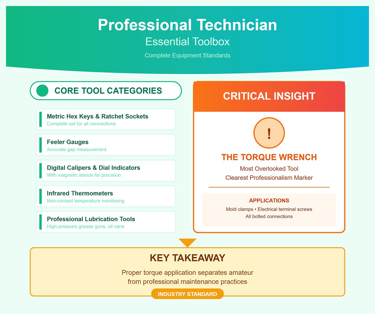
3.5.1 Essential Toolbox: Torque wrenches, feeler gauges, dial indicators, infrared thermometers, and more
- Checklist: A complete set of metric hex keys and ratchet sockets; torque wrenches to ensure precise preload on all bolted connections; feeler gauges for measuring small gaps; digital calipers and dial indicators with magnetic stands for precision measurement; infrared thermometers for quick, non-contact temperature checks on oil, motors, and electrical joints; and a range of professional lubrication tools (e.g., high-pressure grease guns and oil cans).
- Deep Insight: Among this list, the torque wrench is the tool most often overlooked by amateur technicians—but it’s also the clearest marker of professionalism. Whether tightening mold clamps or electrical terminal screws, incorrect torque—whether too loose or too tight—is a hidden root cause of precision loss, connection failure, and even equipment damage.
3.5.2 Strategic Spare Parts Inventory: Identify and stock critical wear items (seals, filters, relays, etc.)
- Class A Parts (Mandatory, High Turnover): Everyday consumables such as hydraulic oil filters, air filters, commonly used relays, contact tips, and fuses.
- Class B Parts (Recommended, Moderate Risk): High-impact wear items where downtime is costly—such as complete seal kits for main hydraulic cylinders and backgauge servo motors, vulnerable encoder cables, foot switches, and light curtain transmitters/receivers. Failures are rare, but lead times may stretch to weeks, potentially causing severe production standstills.
- Class C Parts (Reference Only, High Value): Expensive yet low-failure components like proportional servo valves, servo motors/drives, CNC controller mainboards, and hydraulic pumps. These generally need not be stocked but should be documented—recording model numbers, specifications, supplier contact details, and confirming lead times and emergency sourcing channels.
- Deep Insight: Building a spare parts inventory is a balancing act between financial investment and downtime risk. A highly efficient advanced approach is to proactively form a spare parts alliance with nearby plants that use the same equipment brand and models—sharing information and even physical stock of B- and C-class high-value components. This collaborative network provides strong risk protection at minimal cost.
IV. Advanced Strategies: Beyond the Manual—Toward Predictive and Intelligent Maintenance
When standard maintenance routines become second nature, true excellence begins with going beyond them. The earlier chapters have laid a solid foundation for your maintenance practices; now, this chapter will guide you from being a meticulous executor to becoming a forward-looking strategist. Together, we’ll explore how to harness data, advanced technology, and systematic thinking to transform the maintenance department from a reactive cost center into an intelligent hub that anticipates risks and generates substantial economic value. This is no longer just about “repairing” equipment—it’s about strategically managing the health and future of your assets.
4.1 Data-Driven Decision Making: From Paper Logs to CMMS Digital Transformation
The modernization of maintenance begins with a revolution in how records are kept. Moving away from scattered, smudged, and unsearchable paper logs to fully embracing a Computerized Maintenance Management System (CMMS) is the first—and most critical—step toward maintenance excellence.
- CMMS: More Than “Paperless”—It’s the Enterprise’s Maintenance Brain We must recognize that the true value of CMMS lies not in merely digitizing paper records, but in building a centralized, deeply analyzable “maintenance brain” for the organization. It integrates every machine’s asset log, full maintenance history, spare parts inventory and consumption, work order tracking and closure, as well as all technical documents into a dynamic, interconnected database.
- From Reactive to Proactive Triggers: You can schedule precise preventive maintenance based on calendar intervals (e.g., every 30 days) or actual usage metrics (e.g., every 1,000 operating hours or 50,000 bending cycles). When preset conditions are met, the system automatically generates detailed work orders and sends them directly to the assigned engineer. This automation eliminates maintenance lapses caused by human oversight or communication gaps.
- Deep Insight: Identifying a Machine’s “Failure Fingerprint”: The key differentiator between professional and amateur maintenance is data analysis capability. Mining years of historical data, CMMS can uncover the hidden “failure fingerprint” of specific equipment beneath seemingly random breakdowns. For example, analysis might reveal: “The main hydraulic pump bearing on press brake #3 shows abnormal vibration every 4,150 hours,” which is far earlier than the manufacturer’s recommended replacement at 6,000 hours. Acting on this insight, you could set the preventive replacement interval to 3,800 hours, effectively preventing costly, unplanned downtime at minimal expense. This is the first solid step from “scheduled maintenance” toward “predictive maintenance.”
4.2 Introduction to Predictive Maintenance: Using Vibration Analysis and Thermal Imaging to Detect Issues Early
The core philosophy of Predictive Maintenance (PdM) is to detect early, subtle physical signs that indicate potential problems—before visible symptoms like cracks or machine stoppages appear—using advanced condition monitoring technologies. For press brakes, vibration analysis and thermal imaging are two entry-level PdM techniques that deliver fast, high-return results.
- Vibration Analysis: Listening to a Machine’s “Heartbeat” Every rotating component generates a unique vibration frequency spectrum, much like every person has a distinct heartbeat. Changes in the machine’s internal health will be reflected in alterations to this spectrum.
- Execution Method: Use a portable vibration analyzer to periodically (e.g., quarterly) collect vibration data from fixed measurement points on critical rotating components such as hydraulic pumps and main motors.
- Deep Insight: The Art of Decoding Frequency Spectra: Raw vibration velocity readings (in mm/s) reveal only the magnitude of vibration, whereas FFT spectrum charts show its composition, revealing the true nature of the issue. For example:
- 1× frequency (rotational speed frequency) anomalies typically point to rotor imbalance.
- Significant 2× frequency signals often indicate shaft misalignment.
- Concentrated high-frequency noise is a classic early warning of bearing raceway pitting. This decoding allows you to receive clear alerts weeks or even months before bearing failure leads to severe pump damage.
- Thermal Imaging: Letting Potential Faults Reveal Themselves In the physical world, nearly all energy losses—whether caused by abnormal friction, excessive electrical resistance, or hidden internal leakage—ultimately dissipate as heat. Infrared thermal cameras make these invisible, fault-indicating temperature anomalies visible.
- Execution Method: Conduct regular (e.g., monthly) thermal scans of electrical control cabinets, hydraulic stations, motors, and all moving joints.
- Deep Insight: Look for “Temperature Differences,” Not Just “Absolute High Heat”: The essence of thermal diagnostics lies in comparative analysis.
- Electrical Systems: A properly functioning circuit breaker should have nearly identical temperatures across its three-phase terminals. If one terminal is more than 15°C hotter than the others, it is almost certain that the connection bolt is loose or oxidized—a clear indicator of a potential fire hazard.
- Hydraulic Systems: A normally closed relief valve should have a surface temperature close to ambient when the system is not over-pressurized. If thermal imaging shows it significantly hotter than surrounding pipes, it suggests internal leakage, continuously diverting high-pressure oil back to the tank. This not only identifies a major energy waste but also pinpoints the root cause of abnormal system oil temperature.
4.3 Mastering Tool Management: Advanced Cleaning, Storage, Repair, and Lifespan Techniques
Cutting tools are the “final millimeter” in direct contact with the product, determining its ultimate quality. Master-level, full lifecycle management of these tools can deliver quality and cost benefits beyond expectations.
- Advanced Cleaning and Storage:
- Ultrasonic Cleaning: For complex-structured or finely engraved specialty forming tools, manual wiping often fails to clean thoroughly and risks scratching the surface. Industrial-grade ultrasonic cleaners can safely and completely remove stubborn oil deposits and metal particles from edges and grooves within minutes, without dead spots.
- Smart Vertical Storage: Intelligent vertical lift tool cabinets can save up to 85% of valuable shop floor space compared to traditional shelving. With access control and automated retrieval records, they enable precise tracking of each tool segment, eliminating costly mix-ups, misuse, and losses.
- Repair and Lifespan Management:
- Deep Insight: Building a “Health Record” for Every Tool Set — In your CMMS or dedicated tool management software, create a unique “lifecycle profile” for each critical tool set—or even each individual segment. Record details such as purchase date, machine assignment, total bending cycles/meters, material types, and repair history (including the number of regrinds and amount of material removed). This allows for precise life expectancy assessment and provides solid, data-based guidance for procurement planning.
- Professional Restoration Over Premature Scrapping — Tools showing minor wear don’t necessarily need to be downgraded or discarded. Many reputable tool manufacturers offer high-precision regrinding services that can restore original sharpness and geometry at a fraction of the cost of purchasing new tools.
- Surface Hardening Technologies — For demanding, high-wear applications, consider applying laser surface hardening or PVD coatings (such as TiN or TiCN) to new or refurbished tools. These advanced treatments can double surface hardness and wear resistance, substantially extending the tool’s functional life and dimensional stability.
4.4 Calibration Deep Dive: Step-by-Step Guide to Perfect Angle Compensation and Full-Length Consistency
When working with different materials and varying sheet thicknesses, achieving consistent bending angles requires more than single-point corrections—it calls for a structured, data-driven calibration and compensation system.
- Create a Dedicated “Material–Tool” Compensation Database — Most modern CNC systems allow operators to assign specific angle compensation values for combinations of material grade, thickness, V-die width, and punch radius. Though time-consuming upfront, this precision setup delivers long-term efficiency gains.
- Standardized Implementation Process:
- Select a Reference Material — Start with your most common material (for instance, 3.0 mm-thick Q235 mild steel).
- Run a Test Bend — Use a perfectly maintained standard tool set (e.g., an 85° punch and 24 mm V-die) to perform a 90° bend.
- Measure with Precision — Using a digital protractor, measure the bend angle at three positions—left, center, and right—and take the average (say, 90.8°).
- Input Compensation — In the CNC system’s angle compensation menu, enter a −0.8° correction for that specific combination.
- Systematic Replication — Carefully repeat this process for all commonly used material–tool combinations. Establishing an accurate compensation archive dramatically reduces trial bends and material waste when setting up new programs.
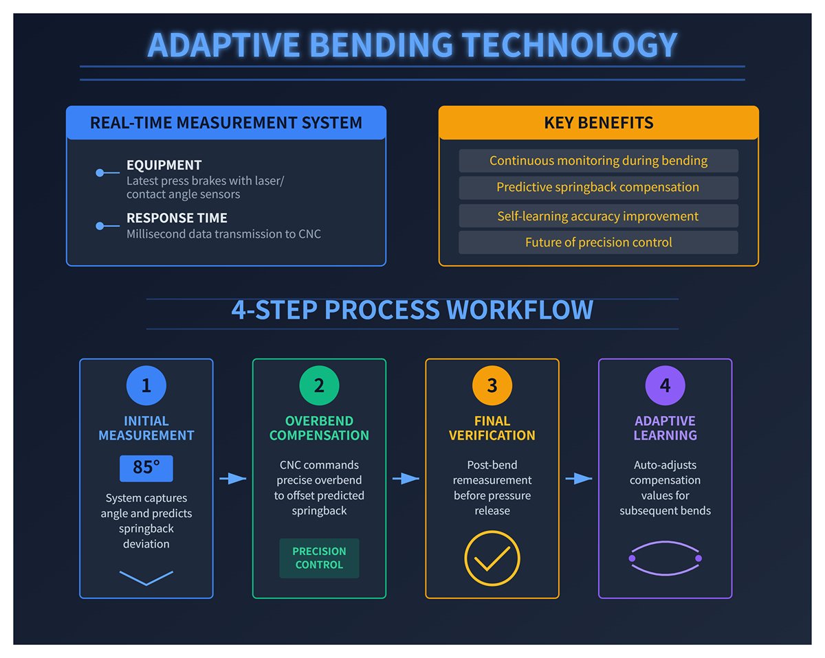
- Deep Insight: Embrace “Adaptive Bending”—Real-Time Angle Measurement and Compensation — The latest generation of press brakes is equipped with laser or contact-based angle measurement systems, representing the future of precision control. These systems continuously measure the angle during bending and send data to the CNC in milliseconds. Their logic is as follows:
- When the bend reaches approximately 85°, the system takes an instantaneous measurement and, based on the material’s springback characteristics, predicts the final angle deviation.
- The CNC then commands a slight “overbend” to precisely compensate for the predicted springback.
- After the bend and before pressure release, the system remeasures the final angle to verify accuracy. If minor deviations remain, it automatically adjusts compensation values for subsequent bends through adaptive learning.
This true “closed-loop control” system virtually eliminates angle variations caused by material batch differences (such as hardness or thickness fluctuations), reducing scrap rates to nearly zero.
4.5 Energy Optimization: Reducing Hydraulic Power Consumption and Noise Through Precision Maintenance
Conventional hydraulic press brakes are often labeled the workshop’s “energy guzzlers” and “noise generators.” However, through meticulous maintenance and forward-looking upgrades, energy efficiency can be improved dramatically.
- Identify and Eliminate Hidden Energy Losses:
- Internal Leakage — As mentioned earlier, using thermal imaging to locate and repair “hot spots” indicating valve internal leakage is the essential first—and most frequently overlooked—step toward reducing energy waste.
- Excessive Pressure Settings — Confirm that system working pressure is set to the minimum level necessary for the current operation rather than the habitual maximum. Excessive pressure forces the pump to perform needless work every cycle.
- Cooling Efficiency — Regularly clean the hydraulic oil cooler’s fins to maintain unobstructed airflow. Dust- or oil-clogged radiators cause fans to run at high load for extended periods, raise oil temperature, and waste energy.
- Deep Insight: From Constant Speed to Demand-Driven Pumping—A Technological Revolution — The inherent inefficiency of traditional hydraulic press brakes lies in their pump design: a fixed-speed induction motor drives the hydraulic pump at full speed regardless of whether the machine is actively bending. This wastes vast amounts of energy during idle and loading phases.
- Servo-Hydraulic (Hybrid) Systems — This state-of-the-art energy-saving technology replaces the conventional motor with a high-response servo motor to drive the pump. Its innovation lies in:
- During idle or material handling, the servo motor slows dramatically—or even stops completely—reducing energy consumption to nearly zero.
- Only when pressing force is needed does the servo motor instantly ramp up speed and torque to deliver precise, on-demand hydraulic power.
- Remarkable Benefits — This “on-demand hydraulic supply” model can cut total energy usage by 50% to 80%. Because the pump often runs at low speed or is stationary, it also significantly reduces machine noise and oil temperature, extending the service life of hydraulic oil and key components such as seals and pumps. For older machines, adding a variable frequency drive (VFD) offers a practical retrofit option. While less responsive than a full servo system, it can still achieve around 30% energy savings.
- Servo-Hydraulic (Hybrid) Systems — This state-of-the-art energy-saving technology replaces the conventional motor with a high-response servo motor to drive the pump. Its innovation lies in:
5. Troubleshooting and Pitfall Avoidance: A Frontline Emergency Guide
Even with the most comprehensive maintenance program, equipment failures and human errors are an inevitable part of shop-floor reality. This chapter isn’t a dry technical manual—it’s a hands-on “emergency guide” and “pitfall checklist” designed for frontline personnel. Its mission is to help you quickly diagnose problems, prevent costly mistakes, and understand a critical truth: amid all uncertainties, it’s the human factor that remains both the strongest and most fragile link in maintenance.
5.1 The Three Fatal Maintenance Mistakes—and How to Avoid Them
Through countless equipment failure analyses, we've discovered that catastrophic breakdowns are rarely caused by rare, high-profile issues. Instead, they stem from three long-neglected, seemingly trivial “fatal mistakes.” Avoiding these is what separates a professional from an amateur—and defines the baseline for keeping equipment running reliably over the long term.
- Mistake 1: Using the wrong hydraulic oil grade
- Fatal Consequences: This is far from the simplistic “any oil will do” notion. The viscosity grade of hydraulic oil directly determines the thickness and strength of its lubricating film. The wrong viscosity can cause abnormal wear on precision components such as pumps and valve spools over millions of high-pressure cycles, gradually eroding accuracy. Even more dangerous, however, is the difference in additive compositions (anti-wear, antioxidant, anti-foam agents) among oil brands and models. Mixing them is like triggering a destructive chemical reaction in the machine’s “bloodstream,” forming sludge and gels that clog micron-sized openings in servo valves, leading to sluggish or erratic slide movement—or causing seals to swell and harden, ultimately resulting in widespread system leakage.
- Prevention: Always treat the equipment manufacturer’s (OEM’s) recommended oil specification as your sole authority. Clearly label the oil reservoir with waterproof tags showing the correct oil name and grade. If a brand change is unavoidable, only use a product that fully matches the viscosity and additive profile of the original—and has the manufacturer’s written approval. Before refilling, use dedicated flushing equipment to completely circulate and clean the entire hydraulic system.
- Mistake 2: Ignoring “minor” leaks or unusual noises
- Fatal Consequences: A single unnoticed oil drop on the floor is often an early distress signal from your machine. One drop per minute equals roughly 200 liters of lost oil per year. But remember—the cost of lost oil is the least of your worries. Every leak point also serves as a gateway for contamination. During each on/off cycle, temperature fluctuations make the oil reservoir “breathe,” drawing in humid, dust-laden air through even the tiniest leak. These microscopic contaminants are exponentially more damaging than the oil loss itself. Likewise, a new unusual noise is a mechanical component’s (bearing, gear, etc.) “cry for help” in the early stages of damage. Ignoring it is like letting a $20 maintenance issue snowball into a $20,000 emergency repair.
- Prevention: Foster a strict team culture of “zero leaks and zero abnormal noise.” Treat every new leak or odd sound—no matter how small—as an incident requiring documentation, reporting, and a corrective plan. Investigate each case like a detective, applying the “Five Whys” analysis until the true root cause is found and eliminated, rather than merely wiping off the oil or getting used to the noise.
- Mistake 3: Poor tooling maintenance triggering a chain of accuracy failures
- Fatal Consequences: Proper care of precision tooling goes far beyond “just clean and store.” Failure to thoroughly clean and apply rust preventive after use can lead to microscopic corrosion along cutting edges—imperceptible pits that, under high-pressure bending, can emboss imperfections onto sensitive materials like stainless steel, creating scrap. More critically and insidiously, unaligned, unclean, or loosely mounted tools cause severe off-center loading during bending. This uneven stress continually and irreversibly distorts the slide guides’ linear accuracy, accelerates deflection-compensation wear, and ultimately causes permanent geometric errors in the entire machine. This is a textbook case of chain failure—a tiny tooling issue escalating into structural damage to the machine itself.
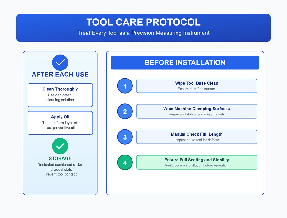
- Prevention: Treat every tool as if it were a precision measuring instrument. Establish an unwavering protocol: after each use, clean thoroughly with a dedicated solution and apply a thin, uniform layer of rust preventive oil. Store tools in dedicated, cushioned racks with individual slots to prevent contact. Before installation, wipe both the tool base and machine clamping surfaces clean and dust-free, then manually check along the full length to ensure the tool is fully seated and completely stable.
5.2 Rapid Troubleshooting and Solutions (Quick Reference Table)
This quick-reference table is designed to help you build a clear diagnostic mindset amid production chaos—following the golden rule of troubleshooting: from simple to complex, from the outside in.
| Issue | Most Likely Troubleshooting Path (from simple to complex) | Key Insights & Solutions |
|---|---|---|
| Inconsistent bending angles | 1. Material variation: Check whether the sheet’s thickness, hardness, or grain direction differs significantly from the previous batch. 2. Tooling issues: Inspect upper and lower dies for wear or chipping, and confirm multi-segment tooling alignment. 3. Workpiece positioning: Ensure operators are placing the workpiece firmly and vertically against the backgauge. 4. Program & compensation: Verify that the correct program is called and the deflection compensation value matches the current process. | Insight: 90% of angle problems stem from material, tooling, or human factors—not the machine itself. Always perform a test bend on new material batches and recalibrate the angle compensation. Align the bending centerline with the machine’s centerline to prevent angle deviation caused by off-center loading. |
| Hydraulic system overheating | 1. Low oil level: Check the tank level—insufficient oil sharply reduces cooling efficiency. 2. Clogged cooler: Inspect air or water coolers for dust and oil buildup, and verify coolant flow. 3. Relief valve pressure: Confirm standby pressure isn’t set excessively high, causing continuous relief valve operation and heat generation. 4. Internal leakage: Use an infrared thermal camera to scan valve groups or pumps for abnormal hot spots indicating internal leakage. | Insight: Overheating is essentially “wasted power.” Cleaning the cooler is the cheapest and fastest fix. If that fails, internal leakage—such as a valve that doesn’t fully close—is highly likely, causing pressurized oil to perform useless work and convert energy into heat. |
| Backgauge drift or inaccurate positioning | 1. Dirty guideways/lead screws: Check linear guides or ball screws for chips, debris, or dried lubricant. 2. Loose timing belt: Remove the guard and inspect the motor’s timing belt tension and wear. 3. Origin switch: Verify that home or limit switches are clean and not loosened by vibration. 4. Servo drive: Check for alarm codes or unexpected parameter drift. | Insight: Before suspecting the expensive servo “brain,” ensure its “legs”—the mechanical parts—are clean and secure. Most backgauge positioning issues originate from neglected cleaning and mechanical checks. |
| Ram slowing down or erratic motion | 1. Insufficient system pressure: Check the gauge; ensure pressure remains stable during rapid descent and bending. 2. Proportional/servo valve: The valve spool may be jammed by microcontaminants or have faulty electrical feedback. 3. Speed transition point: Verify the CNC’s fast-to-slow transition point isn’t set too high or low. 4. Pump wear: Internal pump wear reduces volumetric efficiency, lowering flow and hindering high-speed ram movement. | Insight: Ram motion irregularities—especially impact or delay during fast/slow transitions—usually point to valve control or CNC parameter issues. Persistent overall speed reduction is more likely caused by the power source (pump) itself or insufficient system pressure. |
5.3 Deep Insight: Human Factors—The Hidden Abyss of Maintenance
After analyzing tens of thousands of equipment failure cases, a disturbing truth emerges: most incidents and secondary faults caused by poor maintenance stem not from technology or parts—but from human factors. Yet, simply blaming “lack of responsibility” is lazy and ineffective management. We must understand the deeper psychological and environmental roots that lead to mistakes.
- Three Types of Human Error: According to cognitive psychology, front-line mistakes can be classified into three precise categories:
- Skill-based errors (Slips & Lapses): The everyday “oversights” that occur during routine tasks. For example, forgetting to tighten the final screw after performing a familiar operation thousands of times—an unintentional lapse during “autopilot” mode.
- Rule-based mistakes: Misapplying a rule (“This fix worked last time, so it’ll work again”) or consistently following a flawed shortcut or “old-timer’s method.”
- Knowledge-based mistakes: When facing an entirely new, unfamiliar fault, limited experience or understanding leads to incorrect analysis, judgment, or action.
- The Breeding Ground of Error: Normalization of Deviance
Coined by sociologist Diane Vaughan during her investigation of the Challenger space shuttle disaster, this concept profoundly reshaped how we view organizational failure. It describes a dangerous process: when individuals or teams knowingly violate a safety or operational rule for the first time, discomfort arises—but if no catastrophe follows, the second and third violations feel easier. Over time, this “deviation” becomes the new normal, eroding safety boundaries unnoticed until accumulated risks trigger an irreversible disaster. Examples include repeatedly disabling safety light curtains to speed up work or routinely skipping the full LOTO procedure for convenience—classic cases of normalization of deviance, and the most insidious type of maintenance-related hazard.
5.4 Safety First: LOTO (Lockout/Tagout) and Standardized High-Risk Operations
LOTO (Lockout/Tagout) is not optional—it is a safety regulation written in blood and lives. It forms the final and strongest barrier protecting maintenance personnel from unexpected energy release. Its core principle: before any repair, maintenance, cleaning, or adjustment, ensure the machine is in an absolute zero-energy state.
- The Standard Six-Step LOTO Procedure:
- Preparation & Notification: Identify all energy sources and inform everyone affected (operators, supervisors, etc.).
- Shutdown: Turn off the machine following normal operating procedures.
- Energy Isolation: Locate and disconnect every energy source—such as switching off the main electrical supply and closing air or hydraulic valves.
- Lockout/Tagout: Each maintenance worker personally attaches their own lock and identification tag to the isolation device. One person, one lock, key retained personally.
- Residual Energy Release: Discharge any stored energy. For press brakes, this includes pressing the start button to drain capacitor charge, opening pressure-release valves to vent hydraulic pressure, and—most crucially—using certified physical safety blocks to securely support the ram and prevent accidental descent due to gravity.
Verify Isolation: Attempt to start the machine to ensure it truly cannot be powered on. This is the most critical—and most often overlooked—step! Only after a failed start attempt can you confirm that isolation is effective.
- Grey Areas vs. Absolute Red Lines
A common debate goes: “I’m just changing a tool—it’ll only take a few minutes. Do I really need to go through the full LOTO process?” Some people argue this counts as a minor adjustment during production and can be exempted. This is a dangerously fatal misunderstanding. The clear, indisputable rule is: If any part of your body needs to enter the machine’s danger zone (Point of Operation), you must follow the complete LOTO procedure. Changing a tool obviously falls within this rule. “Saving time,” “being in a hurry,” or “I think it’s fine” can never justify bypassing LOTO. In press brake maintenance, electrical isolation (Lockout) and physical blocking (Blockout) together form a dual safeguard against accidental ram drops and crushing injuries—both are essential, with no room for compromise.
6. Final Mindset: Building a Culture of Excellence in Maintenance and a Blueprint for the Future
Once every technical detail and procedure is second nature, we reach the true “endgame” of this guide—a strategic level that goes beyond quick fixes and focuses on long-term value creation. True excellence does not come from a single technique or a flawless process, but from fostering a maintenance culture that can evolve on its own and continuously generate value. This chapter provides a full blueprint—from mindset to action—helping you turn today’s knowledge into tomorrow’s unshakable competitive advantage, guiding your team from being outstanding executors to visionary industry leaders.
6.1 Core Principles Recap: Three Key Guidelines for Immediate Action
Across this entire book, every complex technology, strategy, and concept can ultimately be distilled into three unshakable core principles. They are the philosophical foundation of any outstanding maintenance system—the constant beacon that guides you through uncertainty. Keep them firmly in mind:
- Financial Principle: Maintenance is a profit center, not a cost center. This is the most crucial mindset shift. We must move away from the passive view of “spending money to fix” toward the proactive view of “investing to generate returns.” Every proactive maintenance action directly improves productive output, extends asset lifespan, and avoids massive financial risks. Its ROI often exceeds that of most other business activities.
- Data Principle: Data—not dates—drives decisions. Replace experience-based guesswork with science-based decisions informed by condition monitoring and historical data. Let objective, honest numbers tell you when maintenance is needed, what needs to be done, and how it should be executed. This is the only path from reactive “fix after failure” to proactive “prevent before it happens,” and ultimately to predictive “foresee the future.”
- Cultural Principle: Full participation, not departmental isolation. Excellence in maintenance is not solely the responsibility of the maintenance department. Operators are the first line of defense for equipment health, production teams are key partners in planning, and management provides essential strategic resources. Only when “caring for equipment and creating value” becomes a shared belief and responsibility flowing through everyone’s veins can a maintenance culture truly take root and unleash unparalleled collective strength.
6.2 30-60-90 Day Implementation Roadmap: A Step-by-Step Plan from Kickoff to Habit Formation
Every great transformation requires a clear, practical action plan. This 90-day phased roadmap is designed to help you systematically turn the concepts in this book into tangible, measurable results on your shop floor.
- First 30 Days: Listen, Assess & Quick Wins
- Objective: Understand the current state, establish a baseline, and secure maximum buy-in from both the team and management with minimal investment.
- Actions:
- Listen to the Frontline: Put down the manuals and engage in one-on-one, in-depth conversations with the most experienced operators and maintenance engineers. Hear about their daily pain points, recurring “problem child” failures, and improvement ideas they’ve long had but which haven’t been implemented.
- Conduct a Comprehensive Audit: Create a digital health record for every critical press brake. Systematically evaluate their current maintenance condition, collect and analyze repair logs from the past 12 months, and pinpoint the machine with the highest failure frequency, longest downtime, and highest defect rate—the “number one problem asset.”
- Execute a Quick Win Project: Identify 1–2 persistent issues that have long frustrated the team and can be resolved quickly (for example, completely replacing all seals on a chronically leaking machine, or designing and implementing a simple, effective 5S tool management system for a chaotic tool storage area). Delivering these wins will spark confidence in the transformation—lighting the first flame of change.
- Second 30 Days: Plan, Pilot & Empower
- Objective: Develop a systematic preventive maintenance plan, validate and refine it through a small-scale pilot, and begin empowering the frontline team.
- Actions:
- Create the PM Plan: Using audit results, select the “number one problem asset” as the pilot and design a detailed, actionable daily, weekly, and monthly preventive maintenance checklist. Ensure each task has a clear owner, a standard operating procedure (SOP), and a completion marker.
- Launch the Pilot Project: Officially begin executing the PM plan for the pilot asset. During this phase, track changes in key performance indicators (KPIs) with scientific rigor—such as increases in mean time between failures (MTBF), reductions in unexpected downtime, and decreases in defect rate.
- Empower and Train: Provide the pilot asset’s operators with systematic autonomous maintenance training—teaching them professional cleaning, inspection, lubrication, and tightening methods. More importantly, give them the authority and formal channels to report even minor anomalies, transforming them from passive “users” into proactive “guardians.”
- Third 30 Days: Roll Out, Standardize & Measure
- Objective: Replicate the pilot project’s success across all assets, cement temporary processes into company standards, and build a data-driven system for continuous improvement.
- Actions:Full Rollout: Using the success metrics and valuable feedback from the pilot, refine and optimize the PM plan, then confidently extend it to every press brake in the workshop.
- Standardization: Transform all verified maintenance procedures, LOTO safety protocols, and inspection checklists into clear, illustrated Standard Operating Procedures (SOPs). Post these permanently in the most prominent position on each machine.
- Establish a KPI Dashboard: Set up a large, visual maintenance KPI board in the most visible area of the workshop. Update it daily with key metrics—such as Overall Equipment Effectiveness (OEE), Mean Time Between Failures (MTBF), and Mean Time to Repair (MTTR)—so that everyone on the team can clearly see the results of their efforts and stay motivated to achieve shared goals.
6.3 Managing Upward: Quantifying and Presenting the Strategic Value of Maintenance Investments
To secure ongoing support and resources from management, technical arguments must be translated into the only language executives truly care about—finance. Stop saying “I need a budget to fix the machines,” and instead state confidently, “I have an investment proposal that will directly increase company profits and reduce operational risks.”
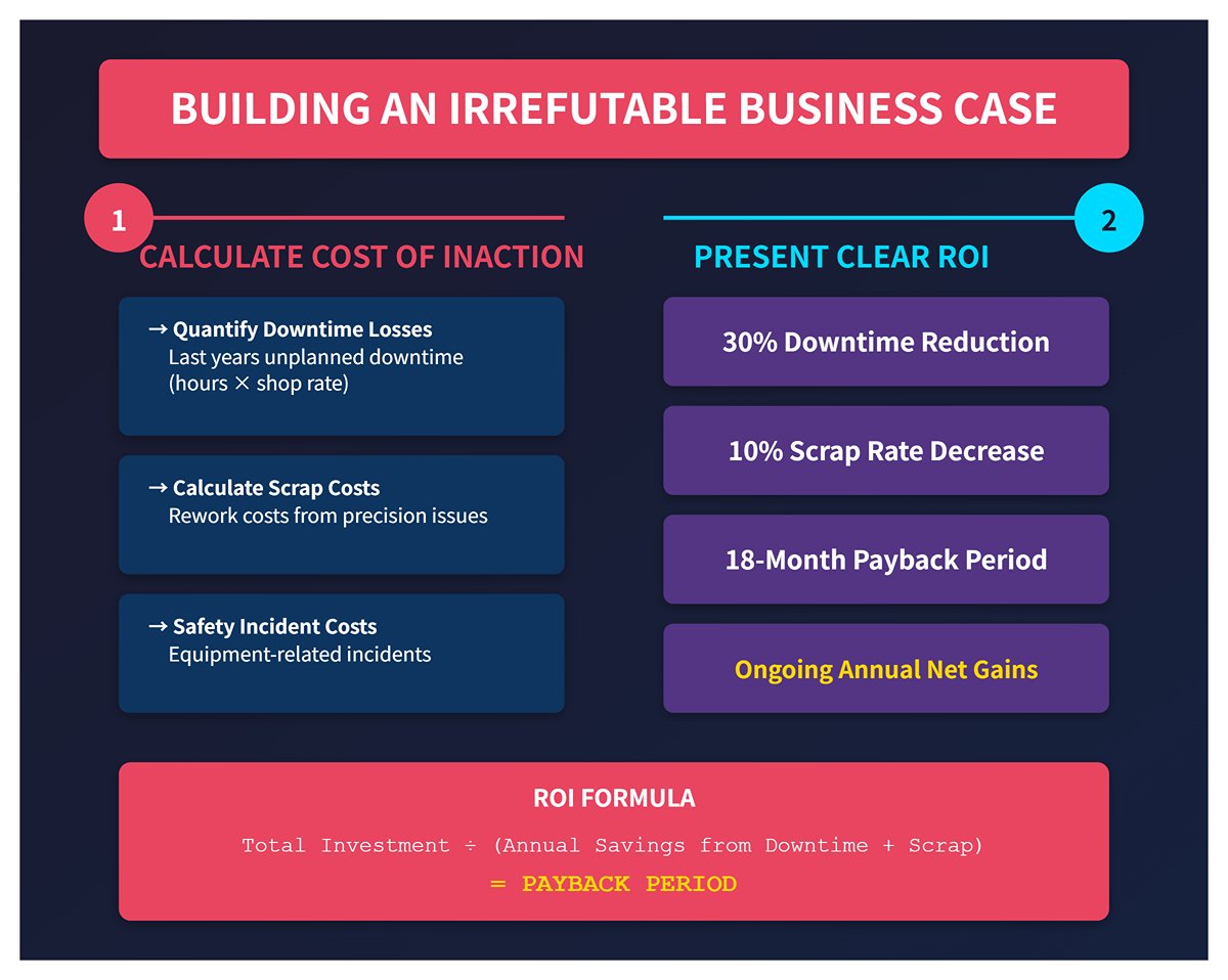
Build an Irrefutable Business Case:
- Step 1: Calculate the Cost of Inaction: This is your problem statement—the “pain point” that captures decision-makers’ attention. Use financial data to quantify last year's losses caused by unplanned equipment downtime (hours × average shop rate), the cost of scrap and rework due to precision issues, and any direct or indirect costs tied to equipment-related safety incidents.
- Step 2: Present a Clear ROI: This is your proposed solution. Based on your maintenance improvement plan, quantify expected returns using conservative and credible data. For example: “By implementing this preventive maintenance system, we expect to reduce unplanned downtime by 30%, recovering XX hours of productive time annually—equivalent to an output value of XX currency units. Scrap rates will drop by approximately 10%, saving XX units in material and rework costs each year. The total investment is XX, with a full payback period of 18 months and annual net gains of XX thereafter.”
Go Beyond the Obvious: Communicate Strategically Using a ‘Value Driver Tree’ This advanced tool connects seemingly operational maintenance activities directly to top-level financial outcomes—such as shareholder return and operating profit—through a clear, visual logic.
How to Present It: During your report, sketch out a simple tree: “Our core financial objective is to increase Earnings Before Interest and Taxes (EBIT). EBIT is composed of two main branches—revenue growth and cost reduction. Our advanced maintenance initiative contributes to both simultaneously:”
On the Revenue Growth side: By systematically improving Overall Equipment Effectiveness (OEE), we can increase total factory output and delivery capability without any additional capital investment, thereby directly driving sales growth.
On the Cost Reduction side: By sharply cutting emergency repair expenses, abnormal spare parts consumption, production waste, and energy losses caused by inefficiencies, we will directly lower operational costs.
Through this approach, you fully redefine how management perceives your role—you are no longer merely a “budget spender,” but a strategic business partner who understands the company’s goals and actively creates value.
6.4 Future Outlook: AI-Driven Diagnostics, Sustainable Maintenance, and Integrated Automation
Excellence in maintenance never ends. Standing at today’s technological frontier, we can clearly envision a future where artificial intelligence, sustainability, and deep automation together shape the next generation of maintenance.
- AI-Driven Predictive and Prescriptive Maintenance is already here. Artificial intelligence is fundamentally reshaping the rules of maintenance.
- From Prediction to Prescription: AI’s power goes far beyond analyzing massive sensor datasets to forecast, for example, “Pump No.3’s Bearing No.2 will fail from wear in 30 days”—that’s predictive maintenance. Advanced AI can integrate production schedules, spare part inventories, technician availability, and logistics time to recommend an optimal action: “Since a planned shutdown is scheduled for next Tuesday and the spare part is in stock, assign Engineer Zhang to perform the replacement, estimated at two hours”—that’s prescriptive maintenance.
- Computer Vision’s Sharp Eye: High-resolution cameras installed at critical machine points, combined with AI image recognition, can monitor continuously and detect subtle oil leaks, fatigue cracks, or surface scratches—issues that human inspection often misses. Its precision and tireless vigilance surpass any manual routine check.
- Sustainable Maintenance: In an era when ESG (Environmental, Social, and Governance) factors define long-term corporate value, the maintenance function has evolved from being a production supporter to a key enabler of sustainability goals.
- A Little-Known Fact: Data from your CMMS directly contributes to the company’s ESG performance reports. By implementing servo-hydraulic energy efficiency upgrades or repairing internal hydraulic leaks, you not only save costs but also generate measurable energy data for reporting: “This year, through maintenance optimization, we reduced electricity consumption by XX kWh—equivalent to cutting XX tons of carbon emissions.” These are no longer internal achievements; they become tangible “green milestones” that enhance corporate reputation and investor confidence.
- Automation and Human–Machine Collaboration: The future smart factory will be highly automated, with maintenance deeply integrated into automation systems. Small maintenance robots will handle high-risk or repetitive tasks—like lubrication in elevated areas or replacing heavy tools. Human maintenance experts will evolve from hands-on technicians to data scientists and tactical commanders leading robotic maintenance teams, focusing on system monitoring, root cause analysis, strategy optimization, and cross-domain innovation.
The “endgame” is not an end—it is the beginning of a new, higher-level cycle. By fostering a culture of maintenance excellence, you are no longer simply safeguarding machines—you are forging the company’s most fundamental and enduring competitive strength, laying the firmest foundation for the grand era of intelligent manufacturing ahead.
VI. FAQs
1. How often should I lubricate my press brake?
The frequency of lubrication for a press brake depends on the specific components and usage. Generally, certain moving parts like the backgauge and guiding systems should be lubricated weekly, while other components such as the guides of the mobile beam may only require yearly lubrication.
Always refer to the manufacturer’s maintenance manual for the exact lubrication schedule tailored to your press brake model, and adjust intervals based on operating conditions, such as multiple shifts. Regular lubrication reduces friction, prevents wear, and ensures smooth operation, but avoid excessive lubrication to prevent dirt and debris accumulation.
2. What is the preventive maintenance on a brake press?
The hydraulic oil and oil filters should be changed after every 2000 hours of operation, or about once a year. Existing oil must be drained and disposed of properly, then the tank should be cleaned, and a new oil filter installed.
3. What is the OSHA regulation for press brakes?
The OSHA standard related to mechanical power press brakes is 29 CFR 1910.212. Point of operation safeguarding is regulated under 29 CFR 1910.212(a)(3)(ii) and shall be in conformity with any appropriate standards.
4. What are the golden rules of press brake operation?
Wear personal protective equipment, such as gloves and goggles. Never wear loose clothing, wristwatch, and rings when operating machinery to avoid being dragged into the danger area.
VII. Conclusion
With proper press brake installation and maintenance, the press brake will well exceed its lifetime. Maintenance of the press brake includes the hydraulic circuit, hydraulic accessories, tooling system, and electronic accessories. Additionally, lubrication of mechanical parts, guide rails, back gauges, axes, ball screws, and other parts is necessary, as well as the cleaning of the foundation.
In addition to keeping the press brake machine clean, it is also important to clean the work area. A clean work area will reduce the frequency of cleaning the machine. Even though your operator and shop staff may be knowledgeable, it is a good idea to keep a trusted service technician or company on speed dial for those issues that aren’t easily resolved. If you need professional assistance or technical support, don’t hesitate to contact us for expert guidance or to explore our detailed brochures for more maintenance insights.


