Press Brake Bending Thickness is the most misunderstood metric in metal fabrication. It is not a single number on a spec sheet, but a dynamic result of tonnage, material science, and tooling choices. This guide moves beyond guesswork, providing the definitive formula for calculating your true capacity and the critical checklist for avoiding catastrophic bending errors.
I. Dispelling Myths and Pinpointing the Real Question
When you type “How thick can a press brake cut?” into a search bar, you’ve already taken a key step toward exploring the limits of sheet metal fabrication. But before we dive into an answer, we need to clarify a fundamental concept that could completely overturn the premise of your question.
1.1 Key Distinction: “Cutting Thickness” vs. “Bending Thickness”
Let me illustrate with a metaphor: Cutting is like a surgeon’s scalpel, designed for precise separation; bending, on the other hand, is like a sculptor’s hands, aimed at reshaping form.
- Cutting uses high-energy heat sources (laser, plasma) or powerful shearing forces (shears) to completely separate the material. The focus is on energy concentration and penetration.
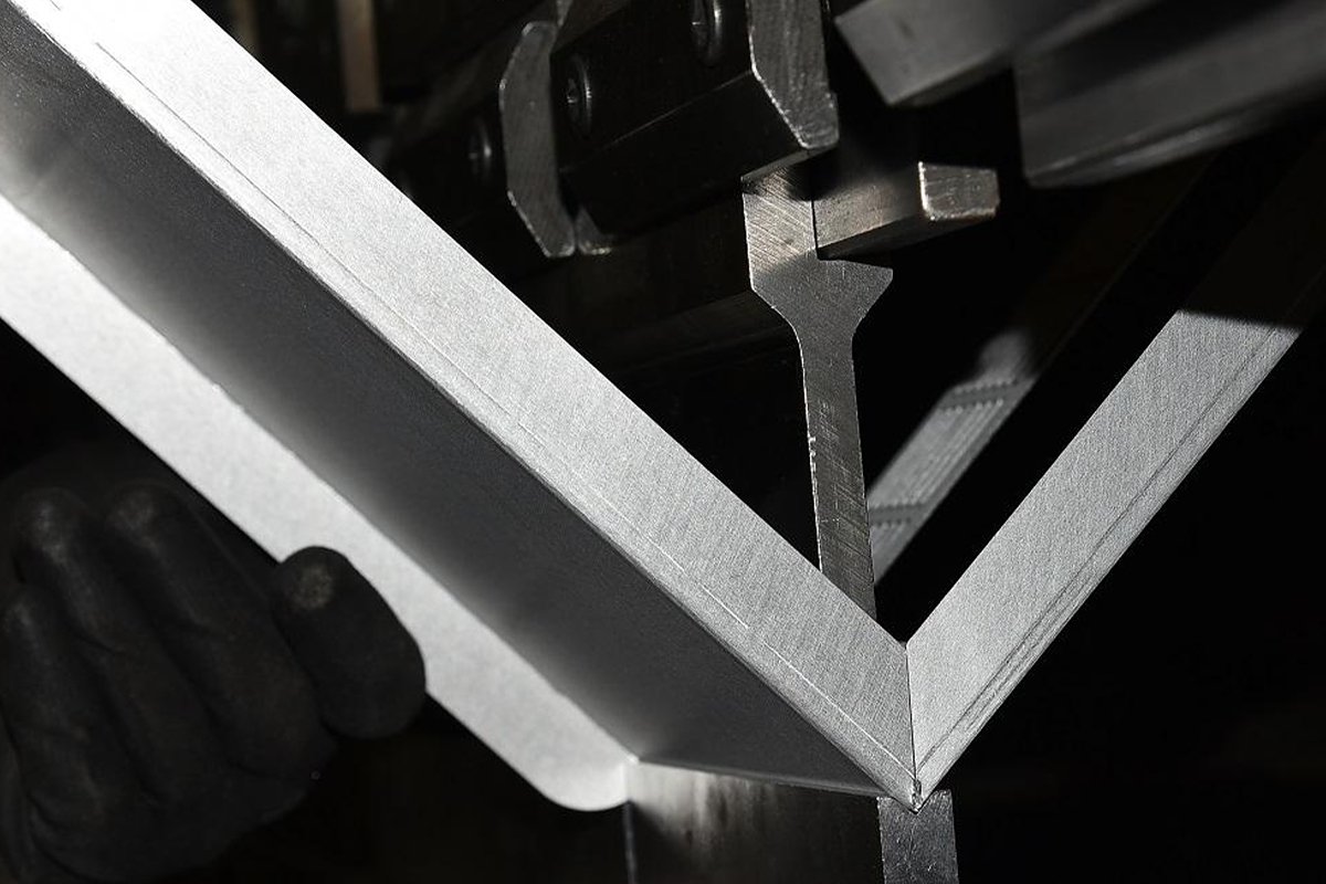
- Bending applies substantial pressure to force metal into plastic deformation without breaking it, focusing on controlled force and the material’s yield point.
These two processes differ entirely in physics, mechanical models, and equipment requirements. A laser cutter that slices through 20 mm steel effortlessly would never be claimed by its manufacturer to bend material of the same thickness. In fact, bending that thickness often requires several times—or even tens of times—the force needed for cutting.
Therefore, your real question isn’t “How thick can a press brake cut?” but rather—“How thick a metal plate can a press brake safely and precisely bend into shape?”
This question has no straightforward numeric answer. It’s determined not by a single parameter, but by a finely tuned mechanical system supported by four fundamental pillars.
To accurately assess a press brake’s maximum capacity, you need to think like an experienced structural engineer, examining the four pillars that support its performance. A weakness in any one of them can sharply reduce the system’s overall load-bearing capability.
- Pillar One: Machine Tonnage – The Absolute Foundation of Force
This is the maximum pressure the press brake can deliver—a starting point for all calculations. But remember, tonnage is only potential power. A key insight: required bending tonnage increases proportionally to the square of material thickness. Double the thickness, and the tonnage requirement quadruples. This exponential jump is why thick plate bending poses such a steep technical challenge. You can further explore this concept in Understanding Press Brake Tonnage for deeper technical insight. - Pillar Two: Tooling – The Intelligent Lever of Force
If tonnage is brute strength, tooling is how you wield it wisely. The V-opening width of the lower die acts as a lever. The well-known “Rule of 8”—using a V-opening eight times the material thickness—is a baseline, but not a universal solution. A wider opening can greatly reduce tonnage requirements, enabling thicker bends, but it sacrifices the inner bend radius. Conversely, forcing thick material into a narrow V risks damaging both tooling and machine. - Pillar Three: Material Properties – The Opponent You Can’t Ignore
Different metals have vastly different “bone hardness”—their tensile strength. Tonnage formulas usually assume mild steel. Switch to stainless steel, and you might need about 50% more tonnage; with soft aluminum, you could need 50% less. Ignoring a material’s temperament and blindly applying formulas is a common cause of project failure and equipment damage. - Pillar Four: Machine Geometry – The Hidden Physical Boundaries
Even if tonnage, tooling, and material are all ideal, the machine’s physical dimensions may impose limits. Throat depth determines the maximum plate width you can feed in, and distance between uprights limits the maximum bend length in a single pass. For thick, oversized plates, these seemingly minor specs often become decisive deal-breakers.
Mastering how these four pillars interact is essential for evolving from a basic operator or buyer into an expert capable of precise evaluation and process optimization. In the next sections, we’ll break each pillar down, offering quantifiable, actionable calculation methods and decision tools.
II. The Underlying Principles: Why There’s No Universal “Maximum Bending Thickness”
The core reason is that metal bending is a complex stress–strain process driven by a dynamic system, not a simple linear relationship. Changing any variable alters the load distribution in non-linear ways. Attempting to summarize it with a single “maximum thickness” figure is simply impractical.
2.1 Source of Force: The Decisive Role of Machine Tonnage
As mentioned earlier, tonnage is the foundation of bending force. Its decisive role lies in overcoming the material’s yield strength.
- Stress and Strain: When the punch contacts the plate and begins pressing, stress (force per unit area) builds within the material. Initially, the metal undergoes elastic deformation—like a spring—returning to its original shape once the force is removed. When stress reaches the yield point, the metal enters plastic deformation, producing a permanent bend. Essentially, press brake tonnage must be sufficient to push most of the material’s cross-section beyond its yield strength.
- Behind the Tonnage Formula: The simplified formula $P \propto S^2/V$ models a three-point bend (punch as one point, die shoulders as two points) where the goal is to make the beam’s (plate’s) center reach yield. The thickness (S) squared term reflects that increasing thickness not only enlarges the cross-sectional area but also raises the section modulus—a geometric property tied to shape and size—at a quadratic rate, demanding disproportionately greater force to induce yield.
- The Little-Known Fact: More tonnage isn’t always better. Excess tonnage leads to “coining,” where the punch forces the material deeply into the die, compressing it thinner at the bend and producing an ultra-sharp inner radius. While coining yields extreme angle precision and repeatability, it greatly accelerates wear on both machine and tooling, and requires 5–10 times the tonnage of air bending. Modern bending typically uses air bending to achieve precise shaping with far less force.
2.2 Core Variable: How a Material’s “Temperament” Influences Bending
A material’s “temperament”—its mechanical properties—is the most complex and unpredictable factor in the bending equation.
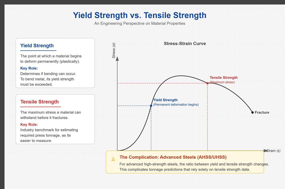
- Yield Strength vs. Tensile Strength: While tensile strength—the maximum stress a material can withstand before breaking—is often used to estimate required tonnage, it is actually the yield strength that determines whether bending can occur. Tensile strength is, however, easier to measure and standardize, making it the industry’s go-to benchmark. Typically, there is a fairly consistent ratio between the two, but for advanced high-strength steels (AHSS, UHSS), that ratio changes, complicating tonnage predictions.
- Ductility and Strain Hardening:
- Ductility defines how much plastic deformation a material can endure before fracturing. Materials with poor ductility—such as certain high-strength steels or cast iron—are prone to cracking on the outer surface during bending, even if the applied force is sufficient.
- Strain Hardening is a key phenomenon: as metal bends, its internal crystal structure undergoes dislocation and slip, which raises both yield and tensile strength in the deformed zone. This means that to keep bending, you must apply more force than was required at the initial yield point. The effect is especially pronounced in stainless steel and some high-strength steels—one reason they demand significantly higher tonnage.
- Springback: Nearly all metals will experience some degree of angular recovery once the upper die is released. This occurs because part of the material—usually near the neutral axis—remains elastically deformed. That residual “spring” action tries to restore the sheet toward its original shape.
- Springback Complexity: The magnitude of springback depends on multiple factors: stronger materials spring back more; wider V-die openings cause greater recovery; and a larger bend radius relative to material thickness also increases it. Predicting and compensating for springback is a core function of CNC press brake software, and a major challenge when bending thick plate or high-strength steel.
2.3 Force Leverage: How Tooling Achieves “More With Less”
Tooling—especially the V-shaped lower die—creates mechanical leverage, transforming the bending model in a way that delivers high force efficiency.
- Lever Principle: In air bending, the force (F) applied by the upper die is distributed across the two shoulders of the lower V-die (each bearing roughly F/2). The V-opening width (V) determines the horizontal distance from the upper die’s center line to the lower support points—this is the lever arm (approximately V/2). According to the lever principle, the bending moment (M) ≈ F/2 × (V/2) = F × V/4. Since the bending moment required to reach material yield is relatively constant, increasing the V-opening width allows the same bend to occur with less applied force (F).
- Formation of the Bend Radius: In air bending, the inner bend radius (Ir) isn’t determined directly by the punch tip radius (Rp); it forms naturally based on the V-die opening. A widely accepted rule of thumb is Ir ≈ V / 6.
- The “Sharp Bend” Threshold: When the material thickness exceeds this naturally formed radius, the bending process transitions into a “sharp bend.” The punch tip begins to penetrate the material, concentrating stress and often causing cracks on the outer surface while sharply increasing the required tonnage. This threshold must be avoided when working with thick plate. To bend such materials safely, use a punch with a sufficiently large radius so that the process remains a “radius bend” rather than a “sharp bend.”
- The Hidden Factor Few Consider: Tool wear is another invisible variable. When the shoulders of the V-die or the punch tip become worn after prolonged use, their geometry changes—directly affecting the consistency of bend angle and radius. In high-precision operations, even minor wear can push parts beyond tolerance limits.
In summary, the limiting thickness a press brake can bend is a dynamic equilibrium point defined jointly by tonnage, material properties, and tooling selection. It isn’t a fixed number you can stamp on a machine’s nameplate; rather, it’s a value that engineers determine for each specific application through a combination of calculation, experience, and deep understanding of the underlying mechanics.
III. The Three-Step Mastery: Precise Rules for Calculating Press Brake Tonnage and Thickness
Accurately calculating bending tonnage is a vital skill for ensuring product quality, equipment longevity, and operator safety. This three-step framework guides you from theoretical computation to practical application, enabling precise prediction of required machine force and preventing the risks and losses caused by trial-and-error operation.
3.1 Step One: Understand the Core Tonnage Calculation Formula
All tonnage calculations derive from a fundamental physics equation that quantifies the relationship between bending force, material thickness, die opening, and material characteristics. The most useful and accurate is the air-bending formula, as it describes the actual mechanical state of the sheet freely bent inside a V-die—precisely how most modern press brakes operate.
- Metric Tonnage Formula: This optimized formula corresponds directly to practical engineering parameters:
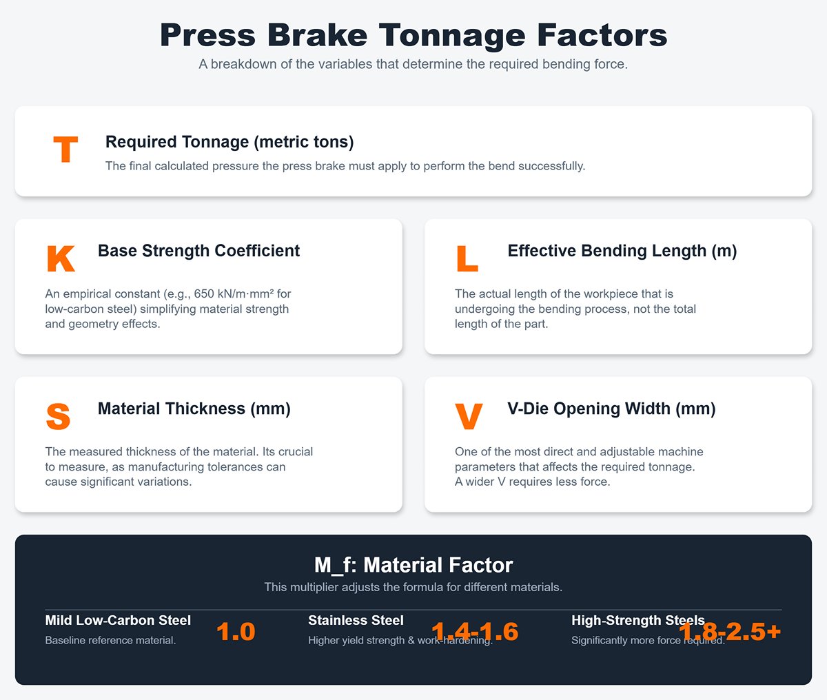
- T: Required tonnage (metric tons)—the total pressure applied by the press brake during bending.
- K: Base strength coefficient. For low-carbon steel with tensile strength around 450 MPa, K is typically 650 kN/m·mm². This empirical constant simplifies the combined effects of material strength, geometry, and the complex stress state during bending.
- L: Effective bending length (meters)—the length actually being bent, not the total length of the workpiece.
- S: Material thickness (millimeters)—always use measured thickness, as manufacturing tolerances can vary between batches.
- V: V-die opening width (millimeters)—one of the most direct and adjustable parameters affecting required tonnage.
- M_f: Material factor, used to adjust the base coefficient K to match different material behaviors during bending.
- Mild low-carbon steel (e.g., Q235/SS400, tensile strength ≈ 400–500 MPa): M_f = 1 (reference baseline).
- Stainless steel (e.g., 304, tensile strength ≈ 550–690 MPa): M_f ≈ 1.4–1.6. Its higher yield strength and pronounced work-hardening effect significantly raise the required tonnage.
- High-strength steels (e.g., AHSS, UHSS): M_f may reach 1.8–2.5 or higher, depending on the specific grade.
- Soft aluminum (such as 1050 or 5052, tensile strength about 100–200 MPa): M_f ranges from 0.5 to 0.7. Because aluminum has a relatively low yield strength, the required bending tonnage is correspondingly smaller.
- Hard aluminum alloys (such as 6061-T6 or 7075-T6): M_f typically falls between 0.8 and 1.2, with strengths comparable to—or even higher than—that of mild steel.
- Key Insight: The essence of this formula lies in the ratio S² / V, which reveals the fundamental mechanics of bending. The required tonnage increases proportionally to the square of the material thickness and inversely with the V-die opening width. In other words, doubling the V opening cuts the required tonnage in half, while doubling the material thickness quadruples it. Grasping this nonlinear relationship is crucial for mastering thick plate bending. Furthermore, the inclusion of the material correction factor allows the formula to extend beyond a single material’s idealized condition and reflect real-world operating scenarios, making its predictions far more practical.
3.2 Step Two: Hands-on Practice and Case Calculation
Bridging theory and practice is the path to true mastery. Now, let’s apply the formula to a concrete case and experience firsthand how powerful tonnage calculations can be.
- Task: Bend a 3-meter-long (L = 3 m), 10-millimeter-thick (S = 10 mm) sheet of 304 stainless steel.
Select the V opening (V): According to the industry-standard “Rule of 8,” the recommended minimum V opening for a 10 mm-thick sheet is 10 mm × 8 = 80 mm. This rule provides a safe starting point for setting the V opening, helping prevent excessive stretching of the material or potential die damage during bending. Hence, we choose V = 80 mm.
- Expert Tip: While the 8× rule offers a baseline, thick or high-strength materials may require a 10× or even 12× V opening. This reduces required tonnage, increases the bend radius, and helps prevent cracking.
Determine the material correction factor (M_f): Since the material being bent is 304 stainless steel, we select a moderately high correction factor of M_f = 1.5, based on earlier references.
Substitute into the formula:
Convert kilonewtons (kN) to metric tons: Since 1 metric ton-force ≈ 9.80665 kN, the conversion is
- Conclusion: To safely and successfully complete this bending operation, you’ll need a press brake capable of delivering at least 373 tons of pressure. This figure represents the theoretical minimum requirement.
3.3 Step Three: Considering Safety and Process Tonnage Margin
The calculated 373 tons is a theoretical minimum—much like a car’s top speed, it’s not advisable to operate continuously at this limit. In actual production, you should never run a machine at its maximum rated tonnage. Always maintain sufficient safety margin; a buffer of 20–30% is typically recommended, and for critical operations or unfamiliar materials, a margin of 30–50% may be warranted.
Why Maintain a Margin?—It’s not just about safety; it’s also about balancing cost and efficiency:
- Material batch variations and uncertainty: Even within the same grade, minor differences in melting or rolling processes cause fluctuations in tensile strength and thickness within tolerance. The next batch might be slightly “harder” (higher yield strength) or a bit thicker, requiring more tonnage than anticipated. Without margin, these small variations can lead to failed bends or machine overloads.
- Machine and tool wear and deviation: Over time, hydraulic seals age, pump efficiency drops slightly, and die shoulders wear under repeated pressure—even microscopic changes increase the tonnage needed for the same bend. A reserve in tonnage effectively absorbs this “depreciation cost.”
- Preventing overload and extending equipment life: Running near 100% capacity accelerates fatigue in hydraulic pumps, seals, hoses, and frame structures, shortening service life and raising failure risk. More critically, it can lead to overheating, frame cracking, or even serious accidents. A machine with built-in tonnage margin operates more smoothly, efficiently, and economically.
- Process flexibility and future scalability: Tonnage margin provides the flexibility to handle more demanding jobs—for instance, using a slightly smaller V opening to achieve a tighter bend radius (though this increases tonnage). It also allows bending coated or uneven surfaces and offers headroom for future materials with greater thickness or strength, avoiding premature equipment upgrades.
- Springback compensation and angle correction: During real bending operations, operators often “overbend” slightly to compensate for material springback, which likewise requires additional tonnage.
Final Tonnage Selection: Considering all these factors, at least a 20% margin should be added to the theoretical result.
What most people don’t realize: For this kind of job, a seasoned engineer would select a press brake rated at 450 tons or more. When purchasing new equipment, it’s always wiser to choose a machine with capacity slightly beyond your current maximum tonnage requirement rather than one that barely meets theoretical limits. Moreover, modern CNC press brake controllers come equipped with advanced tonnage monitoring and limiting systems, allowing the operator to preset a maximum tonnage threshold. If a mistake occurs—such as putting in the wrong material or miscalculating required force—the controller automatically stops the downward stroke the moment it reaches that preset limit, thus protecting the costly dies and machine from damage. This safeguard prevents expensive repairs due to operator error and is a key indicator of a press brake’s intelligence and safety level.
IV. Avoiding Pitfalls — The 5 Deadly Mistakes in Thick Plate Bending
4.1 Mistake One: Relying on Experience Instead of Accurate Calculation
This is the most common—and the most dangerous—error. Many operators depend on their “feel” gained from years of bending thin sheets when tackling thick plates. This approach is fundamentally flawed. They often assume that simply opening the V-die a bit wider and applying more pressure will make everything work, just like thin material. It won’t.
- Faulty reasoning: “I’ve bent 3 mm sheets for ten years; for 15 mm steel, I’ll just use a larger V-die and push a bit harder—it should do.” This mindset ignores physics entirely, reducing a nonlinear problem to a linear one.
- Fatal consequences:
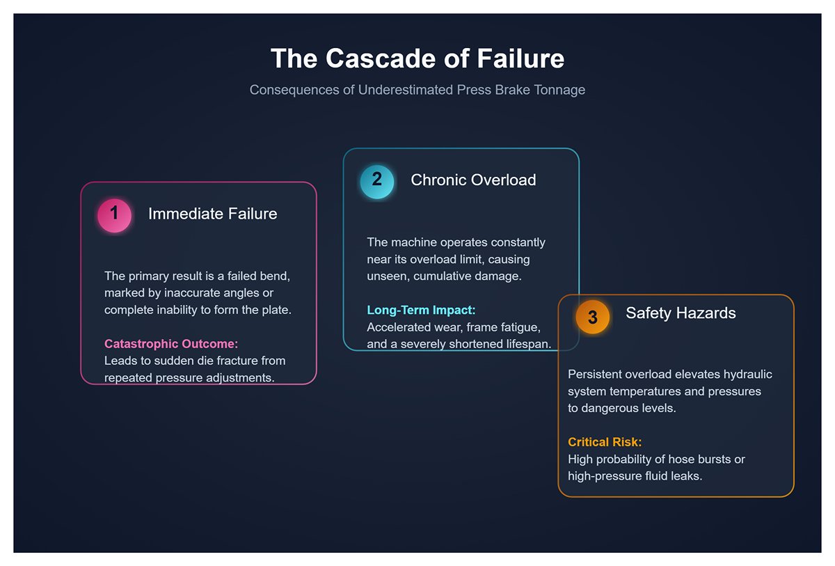
- Underestimating required tonnage: The immediate outcome is failure to form the bend—angles are inaccurate, or the plate simply won’t bend. Repeated pressure adjustments often lead to sudden die fracture.
- Chronic machine overloading: Even if the bend appears successful, insufficient tonnage calculation may keep the press brake operating near its overload limit without anyone noticing. This accelerates hydraulic wear, damages seals, fatigues the frame, and accumulates irreversible stress. The machine’s lifespan shortens dramatically, and sudden breakdowns can occur.
- Safety hazards: Persistent overload raises hydraulic oil temperatures, pressurizes hoses and fittings dangerously, and increases the risk of leaks or bursts.
- Underlying principle: As discussed earlier, required tonnage increases proportionally to the square of material thickness. Doubling plate thickness quadruples the bending tonnage. For example, moving from 3 mm to 15 mm plate multiplies thickness by five, but required tonnage could jump by a factor of 25 (assuming proportional V-die scaling). This exponential increase places the task far beyond what experience alone can manage. Small variations that are harmless in thin-sheet bending become major deviations in heavy plates—relying only on intuition is blind guesswork.
- What most people don’t realize: True professionals never rely solely on theory or past experience. For each new batch of thick material, they cut a small sample and perform a trial bend while watching the CNC readout of actual tonnage. They compare this to the theoretical value to gauge the material’s actual characteristics—its strength, springback, and behavior—and then fine-tune the settings for production. They trust tested reality over paper calculations, combining theory with practice for precision and safety.
4.2 Mistake Two: Chasing a Small Inner Radius (R) by Using an Undersized V-Die
To achieve a sharp, aesthetically small inside radius, some operators recklessly choose a V-die much narrower than the recommended “8× thickness rule.” In thick plate bending, this shortcut is especially dangerous and frequently causes severe die or machine damage.
- Faulty reasoning: “The drawing requires an R of 5 mm. For this 15 mm plate, I’ll use a smaller V-die—otherwise the radius will be too big and won’t meet specs.”
- Fatal consequences:
- Die rupture: The most immediate and dangerous outcome. A narrow V opening concentrates immense bending force on a tiny surface area, creating extreme localized stress. When that stress exceeds the die steel’s strength limit, the punch tip or die shoulder can fracture instantly. High-speed fragments can shoot out like shrapnel, seriously injuring nearby personnel.
- Material cracking: A narrow V forces the plate to “stab” into the die, creating an excessively sharp bend. The outer surface experiences extreme tensile stress beyond the metal’s ductile capacity, leading to cracks or even complete breakage along the bend line—rendering the part scrap.
- Machine damage: Even if the die somehow survives, the enormous tonnage required can deform the ram and bed, misalign guideways, or rupture hydraulic seals—causing permanent precision loss and costly structural damage.
- Underlying principle: In air bending, the inner radius (Ir) is not set directly by the punch tip but primarily determined by the V-die width (V), following the guideline Ir ≈ V/6. When the V opening is much narrower than the plate thickness, the punch begins to pierce or shear the material rather than bending it smoothly. This “sharp bending” mechanism drastically increases tonnage demand and concentrates stress in a small area.
- What most people don’t realize: If a design truly requires a very small inner radius, the correct approach is to machine a V-groove along the bend line before forming, using a dedicated grooving tool. This process thins the material at the bend, dramatically reducing tonnage and tensile stress and enabling small-radius bends safely and efficiently. It’s a standard, professional method—not brute-force bending with a small die. Engineers should discuss this process with clients early in the design stage to ensure the best technical solution.
4.3 Mistake Three: Off-Center Loading—Bending Thick, Short Parts at One End of the Machine
For convenience, operators bending smaller thick parts sometimes position both the workpiece and die at one end of the press brake instead of at the center of the bed. This seems harmless but is actually a silent killer of machines.
- Faulty reasoning: “It’s just a short piece—centering it is extra work. Placing it off to the side saves effort, and since the machine’s tonnage is high, it should be fine.”
- Fatal consequence: This practice introduces severe torsional stress, causing permanent deformation and alignment loss in the machine structure, ultimately leading to costly repairs or total equipment failure.
- Underlying Principle: Modern press brakes—particularly electro-hydraulic models with independently controlled Y1/Y2 axes—are engineered to distribute load evenly across the full length of the worktable. Each hydraulic cylinder (Y1 and Y2) operates via its own proportional valve and linear encoder system, synchronizing precisely to keep the ram perfectly parallel during descent. If you apply excessive bending force to only one side of the machine (for example, the Y1 side), the load between the two cylinders becomes severely unbalanced. To maintain parallelism, the control system will push extremely high pressure into the loaded cylinder (Y1), while the other (Y2) may carry minimal or almost no load. This extreme imbalance can have catastrophic consequences for the machine’s structure:
- Ram Torsion and Guide Damage: In trying to maintain parallelism, the heavily loaded hydraulic cylinder forces the ram upward while the unloaded cylinder does little to assist. This subjects the ram’s mechanical frame and its guide system (gibs) to intense torsional stress. Over time, this leads to uneven wear on the guides, structural fatigue in the ram, and potentially permanent deformation. Once the ram is deformed, the machine can no longer produce accurate angles across its full length, rendering all precision work impossible.
- Hydraulic System Shock: Uneven pressure inflicts severe stress on the hydraulic system, causing premature wear and failure of components such as proportional valves, seals, and hoses on the overloaded side—driving up maintenance costs and downtime.
- Frame Deformation: With extremely thick plate work, eccentric loading can even cause permanent deformation of the machine’s C-frame structure—a serious and often irreparable form of damage.
- What Most People Don’t Know: Many high-end CNC press brakes feature built-in eccentric load monitoring and limits. If the system detects that the load difference between Y1 and Y2 exceeds a preset safety threshold, it will trigger an alarm and immediately halt operation. This safeguard is not there to inconvenience the operator—it’s the machine’s self-protection mechanism, designed to prevent “internal injuries” caused by improper use and to shield costly equipment from irreversible harm. Even with small workpieces, always position them centrally or balance the load evenly to ensure the long-term health of the machine.
4.4 Misconception Four: Ignoring Machine Deflection While Chasing Long-Part Accuracy
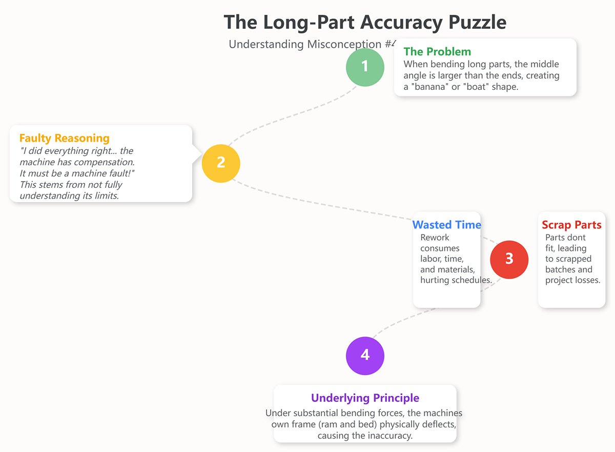
When bending long, thick workpieces, even if your tonnage calculations are spot-on and your technique sound, you may still find that the angle in the middle differs from the angles at the ends—often with a larger angle in the center, producing a “banana” or “boat” shape. This can render the entire part unusable, wasting both material and labor.
- Faulty Reasoning: “I calculated the tonnage correctly, and the machine has a deflection-compensation feature—so why aren’t my bends accurate? Is the machine faulty?” Such confusion stems from an incomplete grasp of how deflection compensation works and its limitations.
- Serious Consequences:
- Scrap Parts: Inaccuracies in long workpieces mean they won’t fit properly with subsequent components, leading to entire batches being scrapped. With thick plate, the high material cost and waste rates can directly cause project losses.
- Wasted Time and Resources: Repeated adjustments and rework to correct deviations consume significant labor, materials, and time—severely impacting production efficiency and delivery schedules.
- Underlying Principle: Under substantial bending forces,
V. Conclusion: From “How Thick Can It Bend” to “How Well Can It Bend”
Mastering press brake bending begins with the core principle that required tonnage is proportional to the material thickness squared and inversely related to the V-die opening. Beyond this formula, true precision demands managing complex variables like material springback and machine rigidity, while always maintaining a 20-30% tonnage reserve and strictly prohibiting eccentric loading for safety.
For more detailed technical specifications and reference materials, you can explore our Brochures to gain deeper insight. Practical mastery involves creating a custom database from real-world bending data, enforcing centered loading protocols, optimizing your tooling inventory for thick materials, and adopting offline programming software to simulate and perfect bends digitally.
If you need tailored solutions or professional guidance for your bending projects, feel free to contact us for expert support. Looking ahead, the industry is moving towards eliminating uncertainty with intelligent technologies; innovations like adaptive control with real-time laser correction, predictive AI models, and synchronized multi-machine bending are ushering in an era where data-driven precision replaces reactive guesswork. Stay ahead of these advancements by partnering with ADH Machine Tool, a leader in modern bending technologies.


