Learning how to align a press brake back gauge is the single most important step toward achieving dimensional accuracy in your parts. While many operators see it as a minor setup task, it is the absolute foundation of precision, and any error—no matter how small—guarantees costly scrap and cumulative inaccuracies.
This guide moves beyond guesswork and provides a definitive, four-stage protocol to achieve true parallelism. We will dissect the causes of hidden errors like thermal drift and backlash, giving you the expert-level knowledge to transform your machine's accuracy from "good enough" to perfect.
I. Core Cognition: The Strategic Significance and In-Depth Analysis of Backgauge Alignment
In modern precision sheet metal fabrication, the backgauge system is no longer a simple “stop block”; it has become one of the neural centers of the entire bending unit. Neglecting its accuracy is like planting a time bomb in the foundation of a skyscraper. Before we discuss the “how,” we must first elevate our understanding to a higher cognitive level.
1.1 The Essence of the Backgauge: More Than Positioning—It’s the Cornerstone of Accuracy and Efficiency
At its core, the backgauge serves as the sole physical reference for bending dimensional accuracy (i.e., flange length). It forms the critical bridge between digital design and physical product. When the operator pushes the sheet metal against the backgauge finger, the position of the backgauge directly defines the distance between the bending line and the edge of the sheet.
- Foundation of Accuracy: During bending, angular precision is governed by the punch depth along the Y-axis, while dimensional accuracy almost entirely depends on the precision and repeatability of the backgauge (primarily the X-axis). For parts with multiple bends, each bend’s cumulative error is directly tied to the backgauge’s precision. If the reference point is off, every subsequent dimension will be incorrect—resulting in scrap parts.
- Foundation of Efficiency:
- Reduced Setup Time: A highly accurate and reliable backgauge system allows the operator to trust the CNC controller’s numerical values completely. There’s no need for repeated caliper measurements, fine-tuning, or trial bends—significantly reducing the setup and adjustment time for the first piece.
- Enabling Complex Bends: Modern multi-axis backgauges (featuring R-axis and Z1/Z2 axes) can automatically lift and shift laterally to avoid pre-bent flanges or support tapered and irregular parts. Without a precise and flexible backgauge system, automated bending of complex components would be impossible.
- Lower Scrap Rates: A stable backgauge ensures dimensional consistency across batch production, minimizing scrap. When working with expensive materials such as stainless steel or aluminum, the economic benefits of precision become even more pronounced.
1.2 Concept Differentiation: The Subtle Distinctions Between Calibration, Alignment, and Referencing
These three terms are often used interchangeably in daily conversation, yet in professional practice they represent different dimensions and cycles of operation. Confusing them is the root cause of many production issues.
| Concept | Calibration | Alignment | Referencing / Zeroing |
|---|---|---|---|
| Essence | Verifies and corrects the absolute accuracy across the full travel of the backgauge—essentially engraving precise markings on the machine’s “ruler.” | Ensures the movement path of the backgauge fingers is perfectly parallel to the bending die (Y-axis)—making sure the “ruler” itself is straight. | Establishes a relative starting zero point for backgauge movement—determining where measurement begins on the “ruler.” |
| Operator | Typically performed by professional service engineers or metrology specialists. | Conducted by experienced operators or maintenance personnel. | Performed daily by machine operators. |
| Frequency | Long interval—annually, or after major servicing, relocation, or collision. | Periodic—weekly or monthly, or after tool changes or detected dimensional deviations. | Frequent—usually after daily startup, job changeover, or tooling replacement. |
| Tools | Precision metrology instruments such as laser interferometers and high-accuracy linear scales. | Gauge blocks, dial indicators, straightedges, or dedicated alignment tools. | Calipers, sample blocks, or built-in controller routines. |
| Consequence | Without calibration, the machine develops nonlinear, cumulative systemic errors across its travel range. | Without alignment, parts emerge with uneven dimensions—wider on one side, narrower on the other—forming a tapered piece. | Without referencing or with incorrect zeroing, all bend dimensions will shift by a fixed offset. |
1.3 Common Pitfalls: Moving Beyond the Illusion of “Close Enough”
Phrases like “looks aligned” or “it’s roughly right by caliper” are among the most dangerous misconceptions in precision sheet metal fabrication outside of heavy-plate work.
- Pitfall 1: Ignoring Cumulative Error and Leverage Effects — A mere 0.2 mm misalignment at the backgauge finger can be amplified across a 1000 mm-wide sheet, resulting in several millimeters of deviation at the far edge due to leverage effects. For parts with multiple bends, this error compounds with each operation.
- Pitfall 2: Overlooking Thermal Expansion — This is a detail only top-level technicians truly appreciate. As a press brake runs for hours, its frame, hydraulic oil, ball screws, and guide rails expand microscopically with heat. The “zero point” set when the machine was cold may drift after reaching operating temperature. For ultra-high-precision jobs with ±0.1 mm tolerances, re-referencing the machine once it’s thermally stabilized is the secret to consistent all-day accuracy.
- Pitfall 3: Ignoring Mechanical Backlash — In older or lower-tier machines, the backgauge drive system (e.g., ball screw or timing belt) can develop mechanical play. When the motor stops and reverses direction, this slack causes a lag in actual movement. Experienced operators know that for consistent positioning, the backgauge should always approach the final stop from the same direction and at a reduced speed. Modern CNC controllers often include “backlash compensation” parameters, but correct setup and periodic validation remain essential.
II. Principles Unveiled: The Structure and Sources of Error in Backgauge Systems
To master the backgauge, one must understand its inner workings as precisely as an anatomist studies the human body. Operational skill stems from a deep grasp of the underlying physics. This chapter takes you inside the “heart” of this precision mechanism—exposing how it functions and identifying the invisible forces that quietly erode accuracy.
2.1 The Backgauge System: A Precision Journey from Digital Command to Physical Accuracy
A modern CNC press brake’s backgauge system is a mechatronic masterpiece that converts digital commands from the virtual world into micrometer-level physical motion. It comprises four core components working in harmony:
- Drive Unit: The Brain and the Muscle — At its core lies the AC servo motor, which, unlike a stepper motor that blindly executes “move N steps,” operates within a closed-loop system capable of self-perception. Equipped with a high-precision encoder, it acts like a sensory nerve, continuously feeding back its exact rotational angle and speed to the CNC controller—the brain of the machine.
- Operating Mechanism: It’s a continuous, ultra-precise dialogue between intelligence and motion.
- Brain Command: “X-axis, advance to 250.00 mm.”
- Muscle Execution: The servo motor rotates, driving the transmission system to move the backgauge accordingly.
- Neural Feedback: The encoder reports in real time, “Control center, I have rotated 2,457.6 degrees; current physical position is at 249.98 mm.”
- Brain Adjustment: “Command not yet complete—continue fine-tuning!”
This closed-loop cycle of command, execution, feedback, and correction is the fundamental guarantee for achieving high-speed, high-precision positioning of the backgauge.
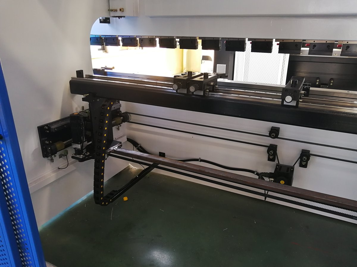
- Transmission System: The Power Expressway – Its role is to convert the servo motor’s high-speed rotation into smooth, precise linear movement of the backgauge beam. The industry’s uncontested standard today is the High-Precision Ball Screw, revered because it replaces inefficient sliding friction with rolling friction, delivering three unmatched advantages:
- Maximum Efficiency: Transmission efficiency exceeds 90%, with minimal power loss and rapid responsiveness.
- Exceptional Longevity: Ultra-low friction and wear ensure stable accuracy over prolonged operation.
- Negligible Backlash: Applying preload to the internal ball bearings virtually eliminates play in the drive mechanism.
- Guiding System: The Absolute Track Guardian – Its mission is to keep the backgauge beam moving in a perfectly straight path, resisting any lateral forces or torsion. Linear guideways are the definitive choice, providing exceptional rigidity and smooth rolling motion to maintain stability and precise direction during rapid acceleration and deceleration, eliminating any sway or drift.
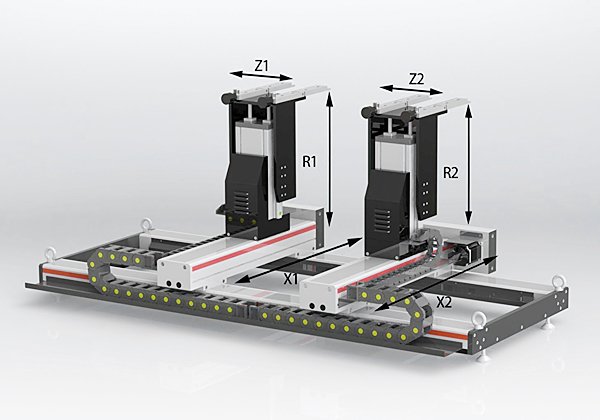
- Multi-Axis System: Agile Limbs – Modern backgauges have evolved beyond a single dimension, gaining multiple degrees of freedom akin to human limbs:
- X-Axis: The core axis, controlling overall forward/backward movement, directly defining bend flange dimensions.
- R-Axis: Controls overall up/down movement, useful for clearing pre-bent flanges or accommodating dies of varying heights.
- Z-Axis (Z1/Z2): Moves the fingers left/right along the beam, providing precise positioning for asymmetrical workpieces.
- Advanced Axes: For example, X1/X2 axes allow each finger to move independently forward/backward, enabling unlimited possibilities for highly complex bends.
2.2 Sources of Error: Where the Ghosts of Precision Hide
Even with such meticulous construction, backgauge accuracy can still drift due to various factors. Understanding these sources of error is essential for effective maintenance and compensation.
- Internal Factors (Innate or Developed Over Time)
- Mechanical Backlash: The primary suspect in accuracy loss. While ball screw backlash is minimal, it still exists and tends to increase with wear over long-term use. When the motor reverses direction, this tiny gap causes a delay in actual movement, undermining repeat positioning accuracy.
- Thermal Expansion: A well-known physical “trick” among top technicians. In high-speed reciprocating motion, ball screws generate heat through friction and elongate. A 1.5 m steel screw will lengthen about 0.018 mm for each 1°C rise in temperature. Continuous heavy-duty operation can raise temperatures by 10–20°C, meaning an extra 0.18–0.36 mm in length compared to its cold state. This explains why a machine calibrated in the morning may show systematic dimensional drift by afternoon.
- Structural Deflection: The backgauge beam is not infinitely rigid. If an operator forcefully slams a heavy sheet against the fingers, it can cause slight permanent bending, disrupting parallelism with the die.
- Encoder Error: Rare, but possible—servo motor encoders can produce false readings due to oil contamination, vibration, or electronic faults, akin to the brain receiving incorrect nerve signals.
- External Factors (Usage and Environmental Conditions)
- Collision: The most direct and violent cause of accuracy loss. Whether the upper die strikes the fingers or the workpiece interferes with them during bending, such impacts can physically deform or displace the fingers, finger mounts, or even the entire backgauge beam.
- Incorrect Zeroing/Alignment: As discussed earlier, using imprecise tools, flawed methods, or performing zeroing in unsuitable machine states (e.g., cold conditions) can introduce a systematic starting error.
- Contamination and Lack of Lubrication: Dust or metal shavings entering the ball screw or linear guide raceways act like clots in an artery, impeding smooth motion, increasing wear, and potentially causing permanent damage.
- Foundation and Level Changes: A press brake’s accuracy depends on a stable, level foundation. Uneven floor settlement or a shift in machine level affects geometric precision, compromising backgauge-to-die parallelism.
Master-Level Insight: The ‘Black Technology’ Behind Top Accuracy – Ever wondered how high-end press brakes counter the ever-present thermal expansion problem? The secret lies in the design. Many premium machines use pre-stretched installation at one end of the ball screw—applying a specific tension during assembly. As the screw heats and expands, this pre-tension offsets part of the elongation. Some even install temperature sensors near the screw, allowing the CNC controller to apply dynamic, micron-level thermal compensation to X-axis positioning commands. This is the true hardcore engineering behind elite precision.
III. Real-World Drill: The Four-Stage Protocol for Nano-Level Backgauge Alignment
Theoretical depth must ultimately serve practical accuracy. This chapter abandons all empty talk to present a standardized, reproducible workflow forged in the world’s top factories. This “Four-Stage Protocol” takes backgauge alignment from a skill based on feel to a precision science grounded in data.
3.1 Stage One: Preparation & Safety First
The foundation of any precision operation is an environment that is absolutely clean and unquestionably safe. This stage’s goal is not adjustment, but the creation of a flawless, interference-free baseline for zero-error measurement.
- Activate Maximum Safety Protocols: LOTO (Lockout/Tagout) — This is absolutely not the same as simply pressing the red emergency stop button. You must rigorously follow the full lockout/tagout procedure: shut off and lock the machine’s main power isolation switch, attach a warning tag stating “Under Maintenance – Do Not Operate,” ensure the hydraulic system is completely depressurized, and secure the ram at bottom dead center or supported by a solid physical block. This is the most fundamental safeguard for your own safety and a hallmark of professional discipline.
- Create the ‘Golden Reference Surface’: Establish an Absolute Benchmark — All precision is ultimately about comparison. Therefore, we first need to create a flawless reference point.
- Dust-Free Zone: Using industrial cleaner and lint-free cloths, meticulously wipe down the press brake’s lower bed and the upper ram’s die-mounting surfaces. Even the tiniest speck of dust, trace of oil, or metal chip can become a magnified source of measurement error down the line.
- Embodiment of the Benchmark: Select the longest, straightest, and least worn upper die you own (a straight blade is ideal) along with a matching lower die, and mount them across the full length of the work table. From this moment on, the centerline of this die set becomes your ‘absolute truth’ for judging parallelism.
- Deploy Your Measurement Arsenal: The Right Tools for the Job
- Main Instrument: High-Precision Dial Indicator — At least one is required; if possible, use two for cross-verification. Resolution must be 0.01 mm or finer; for extreme accuracy, a 0.001 mm indicator is the tool of choice.
- Solid Base: Magnetic Stand — A strong, stable magnetic base is critical to keeping the dial indicator absolutely stationary during measurement.
- Optional Aid: Alignment Rod or Precision Straightedge — A certified perfectly straight, deformation-free metal ruler or specialized alignment rod can provide additional confidence during later checks.
3.2 Stage Two: Baseline Measurement & Deviation Diagnosis
The essence of this stage is to ‘let the data speak’—turning invisible parallelism errors into clear, quantifiable numbers that will guide every subsequent adjustment.
- Define the Measurement Path: Establish a Data Collection Channel — Secure the dial indicator, via its magnetic base, to the ram or the upper die’s shank. Adjust the indicator so its probe is perfectly vertical, with about 1 mm of preload, contacting the front plane of one backgauge finger.
- Perform a Full-Travel Scan: Leave No Error Undetected
- Move the backgauge (X-axis) to a forward position (e.g., X = 100 mm).
- At one end of the machine (e.g., far left), use the Z-axis to position the finger directly in front of the dial indicator probe. At this point, rotate the dial indicator’s bezel to force the reading to zero.
- Switch the CNC controller to manual (JOG) mode and, at a slow, steady speed, move the entire backgauge beam from the far left to the far right, allowing the indicator’s probe to ‘linearly scan’ along the finger’s front face.
- Watch closely and record the full range of readings (highest and lowest) throughout the scan.
- Interpret the Data: Translating Numbers into Physical Reality
- Example: If you zeroed on the left side and, when the finger reaches the far right, the dial shows +0.20 mm, it means the right end of the backgauge is 0.20 mm closer to the operator than the left end. This 0.20 mm ‘taper’ is what needs to be corrected physically.
- Expert Insight: Dual-X Position Cross-Check — Measuring at only one X position is amateur practice. Professional diagnosis requires repeating the full-travel scan after moving the backgauge to a rearward position (e.g., X = 500 mm).
- Case A (Ideal): Taper readings are essentially the same (e.g., +0.20 mm at X = 100 mm and +0.22 mm at X = 500 mm). This points to a straightforward issue: the backgauge beam isn’t parallel to the tooling.
- Case B (Warning): Significant change in taper readings (e.g., +0.35 mm at X = 500 mm) reveals a deeper, serious problem — the backgauge’s travel path (guide rails) themselves are not parallel to the die centerline. Stop adjustments immediately; this likely requires guide rail replacement or complex geometric correction. Seek assistance from a qualified service engineer.
3.3 Stage Three: Precision Adjustment & Iterative Verification
This is the ‘heart’ of the protocol — a micrometer-level surgical operation of bold hypotheses and meticulous validation. Patience and precision are your only tickets through.
- Identify the Adjustment Point: Locate the Mechanism — Find where the backgauge beam connects to its drive unit (typically the ball screw’s carriage). In most designs, one end is a fixed pivot, and the other is an adjustable end. On the adjustable side, you’ll find large locking bolts and nearby ‘push-pull’ set screws for fine-tuning.
- Execute the Loosen–Adjust–Tighten–Measure Micro-Cycle — Using the earlier diagnosis (e.g., right end forward +0.20 mm), our goal is to push the right end backward.
- Loosen: With the correct wrench, slightly loosen the locking bolts at the adjustable end — just enough to allow slight movement under force. Avoid fully loosening them.
- Adjust: Locate the set screw responsible for pushing the beam backward. Turn it clockwise by a very small angle (e.g., 1/8 turn or 45°). Remember: in the micrometer world, even tiny hand movements translate into amplified changes in linear dimensions.
- Tighten: Retighten the locking bolts immediately to the specified torque.
- Measure: Immediately repeat the full-travel scan from Stage Two and check whether the taper has decreased as intended (e.g., from +0.20 mm down to +0.08 mm).
- Iterate Towards Perfection — This process demands extreme patience. Repeat the loosen–adjust–tighten–measure cycle, gradually reducing the error with each micro-adjustment. Like a sculptor removing excess material stroke by stroke, continue until the dial indicator’s variation over the full scan is within your facility’s highest precision standard (e.g., ±0.02 mm).
3.4 Stage Four: Physical Verification & Final Software Calibration
The readings on the dial indicator serve as proof of the process—but the finished bent part is the ultimate judge of truth.
The Ultimate Test: The “Diagonal” Bend Test — This is the gold standard for verifying physical parallelism.
- Select a sufficiently long test sheet (for example, 1–2 meters) with a moderate width (around 200 mm).
- Create a simple bending program. Position one corner of the sheet using the far-left backgauge finger (Z1), then make a 90° bend.
- Next, rotate the sheet 180 degrees along its length, position the opposite corner using the far-right backgauge finger (Z2), and make an identical 90° bend.
- Remove the workpiece and use a high-precision digital caliper to measure the flange dimensions at both ends. If the measurements match exactly—or fall within your tolerance range—give yourself a round of applause: your backgauge has achieved top-tier physical parallelism.
The Final Safeguard: Correct Use of Software Compensation
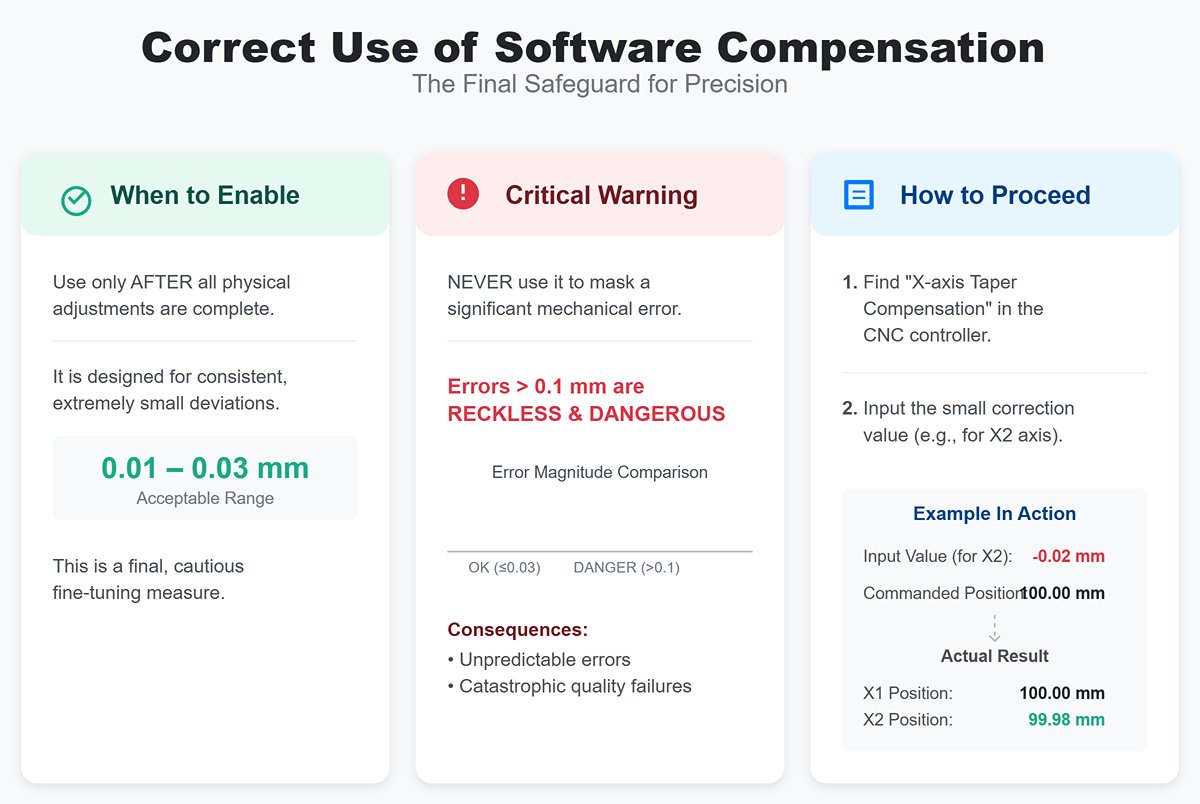
- When to enable: Only after completing all physical adjustments and still having an extremely small (e.g., 0.01–0.03 mm) but consistent residual deviation should you cautiously consider software compensation.
- Critical Warning: Software compensation is meant for fine-tuning—never to mask a significant physical misalignment. Attempting to “cheat” away a mechanical error greater than 0.1 mm with software is reckless and dangerous; it can introduce unpredictable errors at different X-axis positions, ultimately leading to catastrophic quality failures.
- How to proceed: In the CNC controller’s advanced or maintenance parameters, you’ll typically find a setting called “X-axis Taper Compensation” or something similar. This allows you to input a minute correction value for one backgauge drive axis (e.g., X2). For example, entering -0.02 mm means that when the controller commands X1 and X2 to move to 100.00 mm, it will actually drive X2 to 99.98 mm—digitally eliminating the final micro-deviation.
By rigorously completing these four stages, your backgauge system will be perfectly aligned with the die centerline—laying the most rock-solid foundation for all precision production to follow.
IV. Troubleshooting & Maintenance Strategy: Preventing Issues Before They Arise
By now, you’ve mastered the scientific method for precise backgauge alignment. However, true manufacturing excellence comes not from a single flawless calibration, but from a disciplined, systematic approach that maintains peak accuracy over time.
Backgauge precision is cultivated, not merely repaired. In this chapter, we’ll elevate our role from “healer” to “preventive medicine specialist,” establishing a proactive diagnostic and maintenance system.
4.1 Common Alignment Issues & Rapid Diagnosis
When bend dimensions deviate, the worst mistake is to start “turning screws” blindly without diagnosis. An experienced expert works like a skilled physician—examining symptoms, applying logic, and pinpointing the root cause. The diagnostic matrix below is your pocket-sized CT scanner.
| Symptom | Key Characteristic | Prime Suspect | Action Protocol |
|---|---|---|---|
| Fatal “Tapered Part” | One end’s flange dimension is consistently and systematically larger or smaller than the other end. | Physical Misalignment | Stop production immediately. This is the clearest alarm for lost parallelism. Strictly follow the four-stage alignment procedure in Chapter 3 to reestablish the physical baseline. |
| Stubborn “Consistent Offset” | All flange dimensions are precisely off from the target by the same fixed value (e.g., +0.5 mm or -0.5 mm). Highly repeatable, but inaccurate. | Incorrect Referencing | No mechanical adjustment needed. The problem lies in the software’s “zero” point. Perform the daily re-zeroing procedure immediately. Verify that your reference block is accurate and that your method is correct. |
| Ghost-like “Random Error” | Under the same program, consecutive parts vary unpredictably in size, with no discernible pattern—like a haunting. | 1. Excessive Backlash 2. Loose Components 3. Electrical Noise | Perform “touch” and “listen” diagnostics: 1. Use a dial indicator to systematically measure backgauge backlash. 2. With the machine powered down, push and pull the gauge fingers and beam firmly to detect any play or wobble. 3. Check that servo motor cables are secure and not bundled with high-power cables. |
| Progressive “Distance Error” | Dimensions are accurate for short X-axis travel (e.g., X=50 mm) but noticeably off for long travel (e.g., X=500 mm). | Transmission Accuracy Decay | Report immediately and seek professional support. This is beyond routine maintenance—likely uneven wear on the ball screw or expired linear error compensation parameters. A service engineer will need to recalibrate using a laser interferometer. |
| Mysterious “Afternoon Drift” | Parts produced in the morning are flawless, but by afternoon dimensions begin to steadily and systematically shift. | Thermal Expansion | A hallmark challenge of ultra-high precision control. The ball screw lengthens as it heats from friction. Solution: After the machine is fully warmed up (1–2 hours of continuous operation), re-zero to set a new baseline under thermally stable conditions. |
4.2 Maintenance & Preventive Measures: The Four-Tier Care Protocol
Maintaining precision is like conducting a never-ending symphony, with different players—operators, technicians, engineers—performing their parts at defined intervals with exacting accuracy.
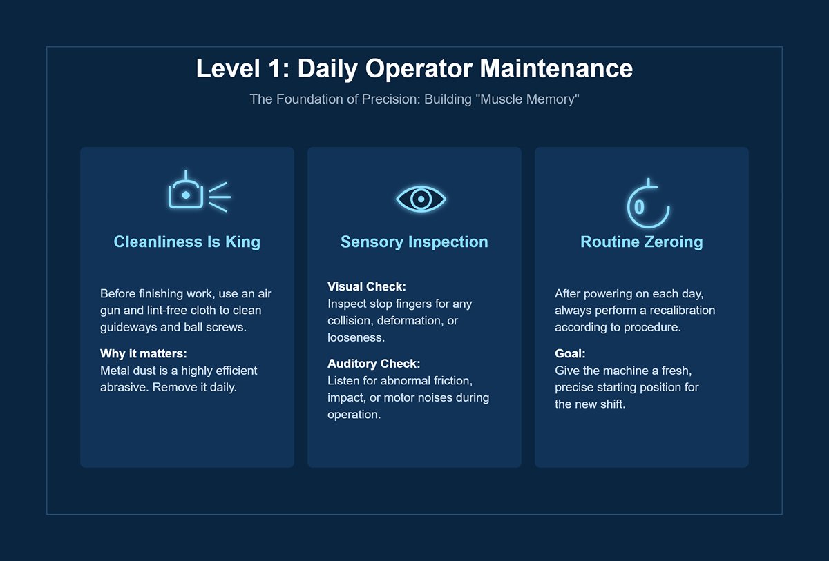
Level 1: Daily · Operator Level
This is the foundation upon which the entire precision structure rests—it’s about building “muscle memory.”
- Cleanliness Is King: Before finishing work each day, use an air gun and lint-free cloth to clean the visible parts of the rear stop’s linear guideways and ball screws. Metal dust acts as the most efficient abrasive—remove it daily without exception.
- Sensory Inspection:
- Visual Check: Inspect the stop fingers for any signs of collision, deformation, or looseness.
- Auditory Check: As the backgauge runs automatically, listen carefully for abnormal friction, impact, or motor noises.
- Routine Zeroing: After powering on each day, no matter how perfect the last shift was, always recalibrate according to procedure to give the machine a fresh, precise starting position.
Level 2 Maintenance: Weekly · Technician Care
This serves as a preventive “quick health check.”
- Random Parallelism Check: Attach a dial indicator to the upper die and quickly scan the full travel of the backgauge. The goal isn’t adjustment but to confirm that parallelism hasn’t shifted significantly.
- Fastener Verification: Ensure that all screws securing the backstop fingers remain tight. Vibration is every screw’s natural enemy.
- Lifeline Inspection: Visually inspect the cable drag chain connecting the backgauge motor to ensure there’s no damage, twisting, or interference.
Level 3 Maintenance: Monthly/Quarterly · Maintenance Level
This is a deep “nutritional boost” and functional assessment for the machine.
- Focus: Precision Lubrication! Follow the manufacturer’s exact recommendations when applying specified grades of grease or oil to the ball screws and linear guides. Expert Warning: Using the wrong lubricant can be just as harmful as none at all—it may trigger chemical corrosion, oil film breakdown, or degraded performance.
- Backlash Measurement & Recordkeeping: Use a dial indicator to systematically measure and record backlash values on the X and R axes. Don’t focus on single measurements—watch the trend. A steady but slightly high value means wear; a sudden increase signals a potential fault.
- Drive Tension Check (if applicable): If your backgauge uses a timing belt drive, verify its tension. Too loose causes positioning delay, while too tight accelerates bearing wear dramatically.
Level 4 Maintenance: Annual · Professional Service
This is the highest level of “complete precision diagnostics,” much like giving the machine an MRI.
- Comprehensive Geometric Calibration: Engage a certified service engineer to use metrology instruments such as a laser interferometer to measure and calibrate positioning accuracy, repeatability, linearity, and parallelism of all backgauge axes, then refresh the CNC system’s error compensation database.
- Servo System Optimization: Specialists can analyze servo drive load curves to assess mechanical smoothness. They will fine-tune acceleration, deceleration, and gain settings to balance efficiency with minimal mechanical stress and energy loss.
Expert Insight: The Invisible Guardians
- The Hidden Threat of Power Quality: Servo systems are highly sensitive to power fluctuations. Voltage instability or high-frequency interference from heavy machinery like presses or welders can inject “noise” into servo controllers, causing random positioning errors. Equipping a top-tier press brake with a dedicated industrial-grade voltage stabilizer or power filter is one of the ultimate secrets to achieving extreme stability.
- The Pneumatic System’s “Breathing”: Many high-end backgauges use miniature air cylinders to lift or eject stop fingers. Regularly inspect for air leaks, stable pressure, and a clean air–oil separator—these are vital for reliable performance. A “short-breathed” finger can be just as fatal to positioning accuracy.
V. Conclusion
In conclusion, the precision of your press brake is not a factory setting, but a standard you actively maintain. We have deconstructed the critical difference between calibration, alignment, and zeroing, revealing that true accuracy lives in the details beyond what the eye can see.
By understanding the mechanical and thermal sources of error—from backlash to heat expansion—and by implementing a rigorous four-stage alignment protocol, you can systematically eliminate the root causes of tapered parts and dimensional inaccuracy.
This journey from a "good enough" mindset to one of scientific precision, supported by a proactive maintenance strategy, is what separates a proficient operator from a true craftsman. It transforms the back gauge from a simple stop into the very bedrock of your quality, efficiency, and profitability. For more insights into precision engineering and bending solutions, explore the latest Brochures from ADH Machine Tool.
Is your team ready to elevate its bending precision to the next level? If you're facing persistent alignment challenges or wish to implement a professional-grade maintenance program, the experts at ADH Machine Tool are here to help. Contact us today for a comprehensive consultation and discover how our deep knowledge of press brake technology can unlock the full potential of your workshop.


