The question of how to build a hydraulic press brake is a serious engineering challenge that ends in failure for most. This is not a hobbyist guide; it is a professional roadmap for the dedicated builder.
We will move from the critical "build-or-buy" decision and detailed design blueprint to a step-by-step fabrication and commissioning protocol. This is the unvarnished truth, designed to ensure you succeed where others have failed. For those aiming to deepen technical mastery beyond this guide, you can explore Advanced Press Brake Techniques to refine your bending precision and process efficiency.
I. Strategy Command Room: Winning 90% of the Battle Before the First Steel Plate is Cut
Welcome to the most critical stage of the entire project—the phase of strategic decision-making. Here, we won’t discuss welding techniques or hydraulic oil types. Instead, we’ll engage in a cold, brutally honest, yet absolutely essential simulation. History is littered with ambitious projects that ended up as rusty, expensive scrap piles in garage corners—and in 90% of cases, their downfall can be traced directly back to misjudgments made during this stage.
Before picturing your powerful machine bending steel plates into perfect angles, pause for a moment. You’re standing at a crossroads: one path leads to a truly valuable production tool; the other, to a bottomless pit that will devour your time, money, and enthusiasm. This chapter is both your map and your compass.
1.1 Build or Buy? A Brutally Honest Pros-and-Cons Analysis and Decision Matrix
Let’s strip away the romantic illusions of “saving money” and the personal urge to “show off skills.” Approach this with the mind of an engineer—a cold, quantitative assessment. The decision matrix below is a reality check that every serious builder must examine line by line.
| Decision Dimension | Build Your Own Hydraulic Press Brake (The DIY Path) | Purchase a Commercial Hydraulic Press Brake (The Professional Path) |
|---|---|---|
| 1. Initial Investment | Deceptively “low.” What you see are material costs—steel and hydraulic components. What you don’t see are outsourcing fees, costs to remake failed parts, the purchase of special tools, and the “trial-and-error” expenses that can easily exceed the raw material value. | Transparent, fixed, and expensive. It’s a clearly defined capital expenditure (CAPEX) that includes R&D, assembly, testing, safety certification, and profit—what you see is what you get. |
| 2. Precision & Repeatability | A massive unknown. Precision depends not only on components but on a triad that’s hard to achieve: ① Rigidity—micron-level deformation control under hundreds of tons of pressure; ② Stress relief—heat treatment for large welded parts; ③ Alignment—accurate calibration with large CNC gantry machines. | Guaranteed out of the factory. That’s the core value of commercial machines. Structures are optimized by finite element analysis, machined on large milling centers, and laser-calibrated to ensure consistent accuracy across the full length and pressure range. |
| 3. Efficiency & Output | Very low. This is fundamentally a long-term R&D project, not a production tool. Most of your time will go into endless debugging, repairing, and optimizing. | Very high. Unbox, install, train, and start producing cash flow immediately. Comes with mature software, quick tool-change systems, and stable performance—predictable productivity from day one. |
| 4. Safety & Legal Liability | Unlimited risk, 100% personal responsibility. A high-pressure hydraulic system (>20MPa) is effectively a bomb. Any weld defect or design flaw can cause catastrophic failure. Legally, as the manufacturer, you bear full liability for all consequences. | Controlled risk, protected liability. Designed under strict international safety standards (CE/OSHA), equipped with light curtains, safety valves, and emergency stops. The manufacturer assumes design safety responsibility. |
| 5. Technical Support & Maintenance | None. You are the only tech support. Forum advice and endless trial and error are your only lifelines. A single critical component failure can mean weeks of downtime. | Comprehensive and professional. Manufacturers provide full parts supply chains, expert hotlines, and on-site repair services—ensuring high equipment availability. |
| 6. Time & Opportunity Cost | Extremely high. A mid-sized hydraulic press brake build can require 400–1500 man-hours—time that could instead generate revenue easily exceeding the cost of a commercial unit. | Almost zero. The lead time from order to production is predictable and manageable, allowing you to focus on your core business. |
| 7. Final Asset Value | Resale value close to scrap metal. It’s a one-off “personal creation” with no brand, no standardization, and no secondary market—useless as a corporate asset. | A defined fixed asset. It follows a predictable depreciation curve and has an active resale market—an investment that can retain or even increase in value. |
1.2 Self-Assessment Checklist: Are You Truly Ready?
Before you spark the welder, confront these questions with absolute honesty. This isn’t a test—it’s a risk audit. If even one answer is “uncertain” or “no,” you should stop immediately, without hesitation.
Level 1: Mechanical & Fabrication Capabilities
- Precision Machining Capability: Do you own or have easy access to large gantry milling or boring machines to precisely machine multi-ton welded frames, ensuring parallelism and flatness of guide and mounting surfaces within 0.05 mm/m?
- Welding & Heat Treatment: Are you proficient in welding thick structural steel plates, and do you have the means to perform full-frame stress-relief annealing to eliminate internal stresses that could cause long-term precision drift?
- Structural Analysis Skills: Can you independently design a frame and ram structure with theoretical deflection under rated load of less than 0.1 mm, and validate it using finite element analysis software (e.g., ANSYS)?
Level 2: Hydraulic & Electrical Expertise
- High-Pressure System Experience: Can you design and build a hydraulic system operating over 20MPa (about 200 kg/cm²) and guarantee absolute safety and zero leakage?
- Valve Knowledge: Do you have a deep understanding of solenoid directional valves, relief valves, and throttle valves, and the ability to select, install, and tune them correctly?
- Electrical Safety: Can you safely design and wire an industrial control circuit including motor starters, overload protection, limit switches, and emergency stop circuits?
Level 3: Resources & Risk Tolerance
- Time Commitment: Have you set aside at least 500 man-hours (roughly equivalent to three months of full-time work) for this project, without it affecting your primary business or income?
- Financial Buffer: Does your budget include at least 20–30% contingency for unexpected costs (e.g., damaged parts, design changes, subcontracting overruns)? And are you prepared for the possibility that one major mistake could double your total cost?
- Risk Awareness: Are you fully prepared to take complete legal and financial responsibility if your homemade machine malfunctions and causes injury or significant property damage?
Final Verdict:
If your goal is to relish the challenge of solving extraordinarily complex engineering problems, without concern for cost or practical output, then building your own hydraulic press brake could be a deeply rewarding intellectual adventure.
However, if your objective is to own a reliable, precise, and safe tool for productive work and profit generation, then there is only one rational choice: purchase a professionally engineered, market-proven machine. This is not retreat—it is strategic wisdom. It allows you to focus your valuable energy on creating true value, rather than endlessly fabricating equipment.
II. Blueprint Bureau: Designing a Machine That’s Powerful, Precise, and Safe
If you thought Chapter One’s strategic planning was abstract theory, welcome to the real battlefield. The Blueprint Bureau is where ideas collide with the laws of physics—where dreams wrestle with budgets. Every line you draw, every tolerance you specify, every component you choose will determine the destiny of several tons of steel.
The blueprint of an amateur is merely an assembly guide; the blueprint of a Chief Engineer is a codex of the future—one that anticipates every possibility and eliminates every fatal flaw. This chapter will teach you how to write that codex.
2.1 Defining Requirements: Three Questions That Decide Success or Failure
Before launching any CAD software, shut down the computer and grab a sheet of paper. Approach it like an entrepreneur reviewing a business plan—cold, clear-minded, brutally honest. Answer the following three questions, which will define your machine’s soul and structure. Their importance outweighs all subsequent technical details combined.
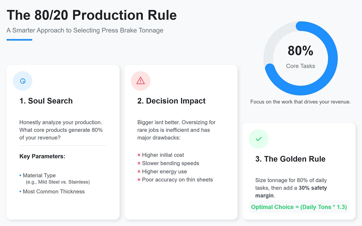
Question 1: What Are You Actually Bending 80% of the Time? (The 80/20 Production Rule)
- Soul Search: Forget that hypothetical “someday” job requiring 20mm stainless steel bends. Instead, analyze with honesty and precision which core products account for 80% of your revenue—whether current or foreseeable.
- Key Parameters: Identify the material type (is it docile mild steel or defiant stainless?) and the most common thickness you work with.
- Decision Impact: This directly determines your machine’s core tonnage. Tonnage is the defining attribute of a press brake—but bigger isn’t always better. Designing for rare, heavy-duty jobs means higher manufacturing costs, slower bending speeds (large cylinders are inefficient at light loads), greater energy consumption, and poorer accuracy on thin sheets.
- Professional Rule: The optimal strategy is to size your machine’s tonnage for 80% of daily tasks, with a 30% safety margin. For example, if your typical 1.5mm stainless sheet requires 30 tons of pressure, a machine rated at 50–60 tons is the golden choice.
Question 2: What Does Your Typical Workpiece Look Like? (The Geometry Rule)
- Soul Search: Close your eyes and picture your most frequent part. Is it a simple flange along a strip—or a complex box that demands deep reach inside the machine to complete its final bend?
- Key Parameters: What is the maximum bending length you need to handle? What is the overall width of your typical workpiece (not just the bending length)?
- Decision Impact:
- Maximum Bending Length: Dictates your machine’s distance between housings and the total bed length.
- Overall Workpiece Width: A crucial yet often overlooked metric—90% of beginners miss it. It determines the throat depth, the distance from the side frame to the upper die’s center. A machine with insufficient throat depth might be 3 meters long but still unable to bend a relatively small 400mm-wide sheet because the frame obstructs it.
Question 3: How Do You Define “Precision”? (The Precision Rule)
- Soul Search: Is your product an artistic piece that allows “close enough,” or an industrial component that demands absolute accuracy? Do your clients measure with a tape or with a coordinate measuring machine?
- Extract key parameters: What are your product’s tolerance requirements for dimensions and angles? Are they within ±1 mm, or as tight as ±0.1 mm? Are your components simple 90° flanges, or do they feature complex multi-angle geometries that require clearance considerations?
- Decision implications:
- Tolerance requirements: These determine how much you must invest in your feedback system. At ±0.1 mm precision, you can’t rely on open-loop control; you’ll need a high-end closed-loop system built around precision linear scales (resolution at least 5 µm) and electro-hydraulic servo proportional valves—both costly, but indispensable for accuracy.
- Part complexity: This affects the required number of axes for your backgauge. For simple flanges, one X-axis (back and forth) is enough. If the workpiece needs to clear pre-bent edges, an additional R-axis (up and down) is necessary. Tapered or irregular parts require independently moving Z1/Z2 axes (left and right)—a standard configuration for advanced systems.
2.2 Structural Design: Building a Frame That Never Deforms
The machine frame is the foundation of precision—the absolute reference for all moving parts. If it bends or twists under hundreds of tons of force, every subsequent effort toward accuracy will be futile.
- Core design principle: Aim for rigidity, not just strength. A typical DIY approach assumes “if it’s thick enough, it won’t break”—a dangerously wrong mindset. Professional design focuses on rigidity: minimizing elastic deformation of the frame and moving beam under full load (generally required <0.1 mm per meter), and ensuring deformation is uniform. Fracture is an accident; deformation is a permanent precision failure.
- The necessity of Finite Element Analysis (FEA) Don’t design by instinct. Today, even free CAD tools like Fusion 360 include robust FEA capabilities. Apply loads to your 3D model—like an X-ray scan, FEA reveals stress concentrations and deformation magnitudes. This helps you achieve maximum rigidity with minimal material by intelligently adding reinforcing ribs and adjusting geometry, instead of blindly piling on steel.
2.3 The Power Core: Hydraulic System Matching Strategy
The hydraulic system is the machine’s source of power—and the key actuator for CNC closed-loop control. The quality of your choices here will directly determine the machine’s level of “intelligence.”
- Core component: Electro-hydraulic Servo Proportional Valve — This is not optional; it’s essential for a CNC press brake. To achieve real-time, micron-level synchronization of the Y1 and Y2 axes, this valve is indispensable (choose top brands like Bosch Rexroth, Parker, or Eaton). It interprets subtle voltage commands (e.g., 0–10 V) from the CNC controller, precisely and continuously modulating hydraulic flow and pressure—like a finely tuned mechanical hand.
- The key difference: A standard solenoid valve has only two states—on and off—like a light switch. It cannot offer positional or speed precision, reducing the machine to a hydraulic press that merely stops at limit switches.
- The closed-loop interplay between linear scales and proportional valves This control logic operates like a skilled race driver managing throttle and brakes:
- Command (Brain): The CNC controller issues an order—“Y1 axis, move to -100.05 mm at 50 mm/s.”
- Execution (Throttle/Brake): The controller sends a precise voltage to the Y1-side proportional valve, adjusting the hydraulic flow accordingly.
- Sensing (Eyes): A high-precision linear scale mounted on the Y1 frame continuously measures the ram’s absolute position, feeding data back to the controller thousands of times per second.
- Error detection (Micro-adjustment): The controller compares the target position (-100.05 mm) to the actual feedback (say, -100.03 mm) and detects any deviation.
- Correction: The controller instantly fine-tunes the valve voltage, increasing or decreasing oil flow to eliminate the error in real time.
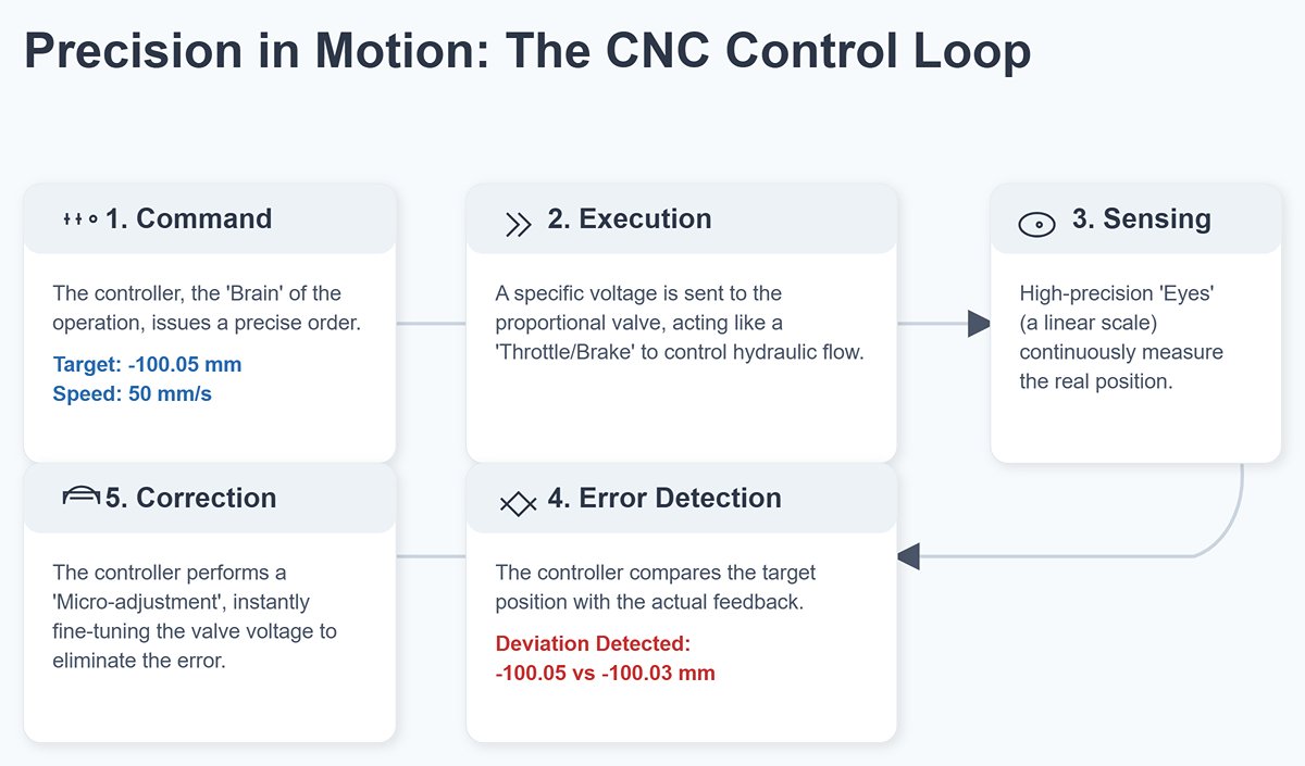
This “command–execute–sense–correct” loop runs hundreds or even thousands of times per second. It forms the heartbeat of CNC closed-loop control, ensuring both sides of the ram remain in perfect micron-level sync—even under uneven loads.
2.4 Source of Precision: Die System Configuration
The die set is the machine’s direct language of communication with the workpiece. A wrong “dialect” produces nothing but scrap.
- Iron rule: Never fabricate your own dies. Professional press brake dies are made from high-carbon tool steel (e.g., 42CrMo), hardened, tempered, and high-frequency heat-treated at the blade edge (HRC 47–52), then ground as a whole with precision surface grinders. These demands are far beyond what an ordinary workshop can achieve.
- Choose one standard, embrace one ecosystem. In tooling, the single smartest decision is to adopt a mainstream global standard.
- Top recommendation: European/Promecam type. This is currently the world’s most widespread, universally compatible standard. By selecting it, you gain access to thousands of standard and custom dies from countless global suppliers—ensuring the broadest availability and the best cost-performance ratio.
- Key point: Once chosen, the punch clamping system (upper die interface) and the die holder on your worktable must strictly conform to the selected standard in both design and manufacturing.
2.5 The Ultimate Bill of Materials (BOM) and Tool Library
This list is a reality check—a distilled summary of what truly determines success or failure. It doesn’t include every screw, but it does capture every crucial lifeline.
- Structural section
- High-strength structural steel plates (e.g., Q345 / S355JR, thickness 15–80 mm)
- [Hidden cost] Outsourced large-format laser or plasma cutting services
- [Hidden cost] Post-weld stress-relief annealing services
- [Hidden cost] Precision machining on large gantry mills (e.g., guide rail and reference surface finishing)
- Hydraulic section
- High-precision main cylinders × 2
- Electro-hydraulic servo proportional valves (with integrated amplifiers) × 2
- High-pressure variable piston pump or precision gear pump
- Three-phase asynchronous motor (power matched to oil pump)
- Integrated manifold block assembly and cartridge valves
- High-pressure seamless tubing, hoses, and premium Parker-standard fittings
- Hydraulic oil tank (usable capacity > 3× pump’s minute flow), high-precision filters, and air- or water-cooled heat exchangers
- Control & electrical section
- Industrial-grade CNC press brake controllers (entry-level models from brands such as Delem, Cybelec, or ESA)
- High-precision linear scales (resolution ≤ 5 µm) with two reading heads
- AC servo motors with drivers for the backgauge (configured according to the number of axes)
- High-precision ball screws and heavy-duty linear guides for the backgauge
- Safety PLC module or safety relay
- Dual-hand operation console, emergency stop buttons, and foot switches
- Professional-grade electrical cabinet fitted with Schneider or Siemens series contactors, circuit breakers, switching power supplies, and cabling
- Tooling & Tools
- European-standard upper die quick-clamping system (manual or hydraulic)
- European-standard lower dies and die holders
- A starter tooling set (for example, one 85° sharp upper die and one multi-V lower die)
- [The Mother of Accuracy] Precision Measurement Toolkit: frame-type level with 0.02 mm/m accuracy, dial indicators with 0.001 mm resolution and heavy-duty magnetic bases, a set of precision gauge blocks for calibration, large-format vernier calipers, and a 90° precision square. Without these, final assembly and calibration will be impossible—like trying to embroider while blindfolded.
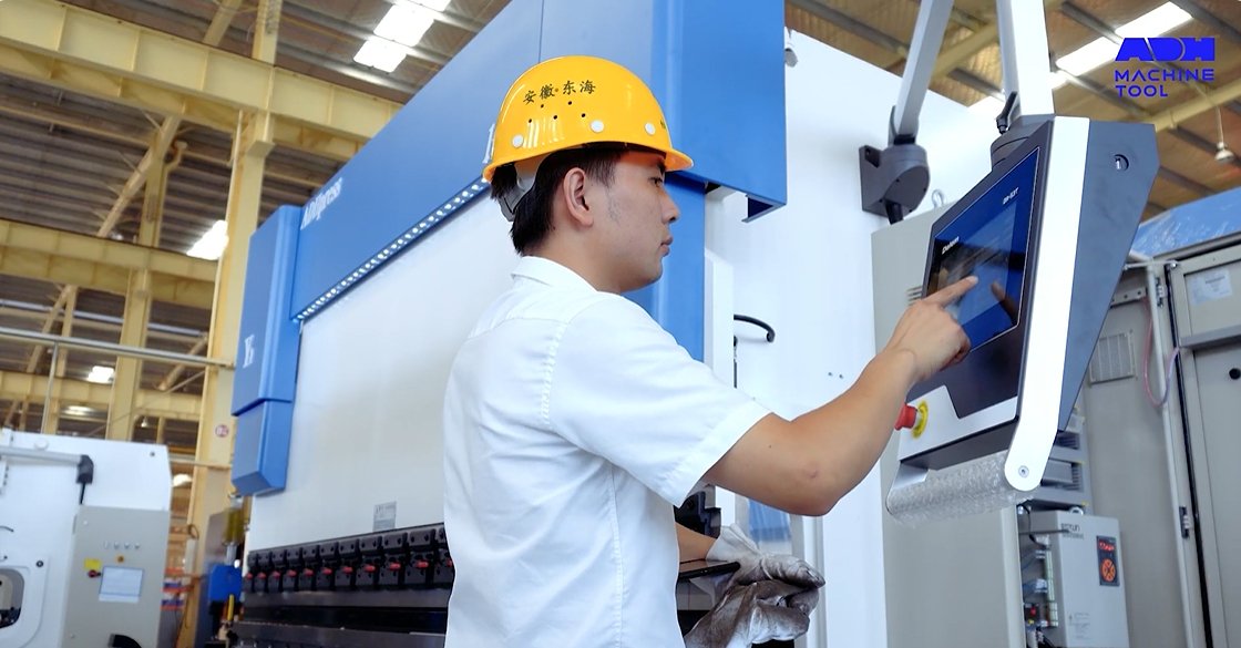
III. The Workshop – A Step-by-Step Practical Guide from Steel Plate to Precision Tool
At this stage, your theoretical blueprint enters the realm of cutting fluid and welding sparks. Welcome to the “Workshop,” where virtual design is forged into physical reality. Here, every millimeter of deviation, every careless weld, every loose bolt will be magnified by the relentless force of hydraulics—leaving costly marks of failure on steel. This phase tests not your passion, but your discipline, patience, and absolute respect for the laws of physics.
3.1 Phase One (Days 1–7): Forging the Skeleton — Cutting, Welding, and Calibrating the Frame
This is the foundation of the entire physical build—and the stage with the highest failure rate. The frame is the machine’s “absolute reference.” Its inherent precision defines the upper limit of your final machine’s accuracy. A single mistake here is nearly irreversible unless you’re willing to remelt several tons of steel.
3.1.1 Precision Cutting: Dimensional Accuracy Is the Starting Point
- Action Directive: Send your CAD drawings (preferably in DXF or DWG format) directly to a professional supplier equipped with large-scale CNC laser or high-precision plasma cutting capabilities. This is your first outsourcing expense—and by far the most cost-effective one.
- Professional Warning: Never use a handheld grinder or plasma cutter on any main structural component. This is not a question of skill—it’s a matter of physics. The slight angular deviations and thermal deformation caused by handheld tools will accumulate during welding, eventually turning into catastrophic geometric errors.
- Expert Technique: When submitting drawings to your supplier, clearly mark all surfaces that will later require precision machining (such as guide rail mounts, cylinder flange faces, and worktable planes). Specify a machining allowance of 3–5 mm on these areas. At this stage, your goal is to obtain a geometrically accurate “blank,” not a finished piece. This allowance provides crucial room for later corrections during precision machining.
3.1.2 Pre-Weld Assembly: Ensuring Perfect Squareness of All Components
- Action Directive: Before striking an arc for any structural weld, perform a full “mock assembly.” Arrange all cut steel plates on a level surface using as many heavy-duty angle clamps, F-clamps, and G-clamps as you can find, following the design drawings precisely.
- Core Objective: This is not mere assembly—it’s a “three-dimensional verification.” Use long steel tapes, precision levels, and large squares to repeatedly check every key vertical, parallel, and perpendicular relationship.
- Operational Essence: Begin by temporarily fixing critical structural nodes with small tack welds. Then perform a thorough geometric measurement. Key checkpoint: Measure the lengths of the two diagonals across the main frame structure; their difference must be kept within 1 mm. If it exceeds that, adjust using copper and sledge hammers. Proceed to full welding only when all geometric relationships are confirmed and the frame is securely fixed in place.
3.1.3 Structural Welding Techniques: Best Practices for Thick Plate Welding and Post-Weld Stress Relief
- Welding Method: For structural plates thicker than 10 mm, use a multi-layer, multi-pass welding process. Never attempt full penetration in a single high-current pass. The correct procedure is to grind a V- or X-shaped groove, then fill it layer by layer like embroidery. To minimize distortion, strictly follow the symmetrical welding principle—after completing a section at point A on the left, immediately weld the matching section at point B on the right. This alternating heat input helps balance internal stresses.
- Post-Weld Stress Relief: The Critical Line Between Success and Failure
- Severe Warning: This is the step that 99% of DIY builders skip—either for cost reasons or out of ignorance. It is also the reason 99% of homemade machines end up as rough “hydraulic toys” rather than true precision tools.
- Action Directive: After all structural welding is complete and the welds have cooled, transport the entire frame to a professional heat treatment facility for full annealing.
- Deadly Consequences of Skipping This Step: The immense internal stress generated during welding behaves like a trapped demon—it will slowly release over months or years, twisting and stretching your frame. All your precision calibrations will be ruined. You’ll notice that bending angles drift unpredictably and never stabilize. Remember this iron rule: a welded frame without annealing is nothing more than a heap of stressed scrap metal—it can never serve as a stable machine base.
3.1.4 Precision Alignment: Using Diagonal Measurement and Levels to Ensure Vertical and Parallel Accuracy
- Timing: Perform this inspection after annealing but before precision machining. This is the final acceptance of your structural “skeleton.”
- Action Directive: Mount the annealed frame on a known perfectly level platform (such as a large cast-iron surface plate). Using a frame level with an accuracy of 0.02 mm/m, carefully check the horizontal alignment of the base and top beam. Re-measure all key diagonal dimensions and record the data. These measurements will serve as essential reference points for the machining shop when determining alignment and processing adjustments.
3.2 Phase Two (Days 8–12): Installing the Heart — Hydraulic System Assembly and Piping Layout
Once the sturdy frame is in place, it’s time to implant its powerful core—the hydraulic system. This is the source of force, but also of potential danger. Every connection must be treated with the same seriousness as working on a high-pressure vessel.

3.2.1 Hydraulic Cylinder Installation: Ensuring Absolute Vertical and Concentric Alignment
- Core Principle: The central axis of the hydraulic cylinder must remain perfectly parallel to the motion guide rails of the moving beam. Even a slight off-center misalignment will generate destructive lateral forces under high pressure, rapidly wearing out seals and causing internal or external leakage.
- Operational Tip: After the hydraulic cylinder is roughly secured, manually move the moving beam close to its bottom dead center. Using a precision square and feeler gauges, carefully check the contact and perpendicularity between the cylinder’s flange and the machine frame’s mounting surface. Take measurements at several positions to ensure consistent alignment throughout the entire stroke.
3.2.2 Hydraulic Line Safety Layout: Prevent Wear, Interference, and Sharp Bends
- Safety Rule: The rated working pressure of all high-pressure hydraulic lines—whether rigid or flexible—must be at least 1.5 times higher than the system’s maximum design pressure. Pay special attention to fittings: only use high-quality, reputable brand components.
- Layout Principle: The routing of hydraulic lines should be as smooth as a highway. Avoid 90-degree elbows, as they cause major pressure losses and fluid turbulence. Instead, form gentle curves using a large-radius tube bender, or connect two 45-degree fittings to create a gradual transition. All lines must be firmly secured to the frame with specialized clamps to prevent vibration from pressure pulsations. Ensure no line rubs against other parts—persistent friction can eventually wear through even the strongest steel tubing.
3.2.3 Installation of Oil Tank and Control Valves: Prioritizing Accessibility and Maintenance Space
- Heat Dissipation Consideration: The hydraulic oil tank is not just a reservoir—it serves as the system’s main heat exchanger. Install it in a well-ventilated area, with sufficient clearance from the ground to allow air to circulate underneath.
- Ease of Maintenance: The manifold block should be placed in a location that allows easy observation and operation. Always leave enough space for manual activation of solenoid valve emergency buttons, adjusting relief valve pressure, or replacing valve cartridges in the future.
3.2.4 System Air Bleeding: Essential Techniques for Removing Air After Initial Oil Filling
- Hazards of Air: Air is the number one enemy of hydraulic performance. Because it is compressible, air can cause sluggish or weak cylinder movement, “creeping” motion, and harsh noise. Under extreme pressure, compressed bubbles can generate localized heat through the diesel effect, potentially damaging seals.
- Professional Bleeding Procedure:
- After filling the oil tank for the first time, let it sit for at least one hour to allow large air bubbles to escape naturally before starting the motor.
- With no load applied, set the system pressure to its lowest value and very slowly raise and lower the moving beam through its full stroke several times (at least 10 cycles).
- Advanced Technique (Warning: Risky Operation—Wear Safety Goggles and Gloves!): When the moving beam is at its topmost position and pressure is maintained, very slowly and slightly loosen the fitting on the topmost port of one cylinder (usually the inlet to the rodless chamber) until you hear a hissing sound and see a small amount of oil seep out. Then, promptly tighten it. Repeat for the other cylinder. This step effectively releases trapped air at the system’s highest points.
3.3 Phase Three (Days 13–15): Installing the Arms—Moving Beam, Worktable, and Die Holders
With the frame and heart in place, it’s time to install the machine’s “arms” and “hands.” The precision of this step directly determines whether the angles of your bent parts will be consistent.
3.3.1 Ensuring Perfect Parallelism Between Moving Beam and Worktable
- Importance: This is the second most critical precision parameter after frame accuracy. It ensures that the pressure exerted by the upper die is uniform along the entire bending length.
- Calibration Method: Place three (or four) equal-height precision gauge blocks on the left, center, and right of the worktable (large bearing rings can serve as substitutes). Slowly lower the moving beam until it lightly contacts the blocks. Then, use feeler gauges to measure the gap between the beam’s lower surface and each block. Adjust the side guide mechanisms—typically adjustable wedges or bronze wear pads—until all measured gaps are less than 0.05 mm or the thinnest feeler gauge cannot be inserted.
3.3.2 Installing and Aligning the Die Holders

- Cleanliness Is Fundamental: Thoroughly clean the mounting surfaces of both upper and lower die holders with a solvent to remove any oil, chips, or dust. Even a tiny particle of metal shavings can compromise flatness and precision.
- Alignment Is Key: After securing both die holders, install your straightest, most accurate set of upper and lower dies. Lower the upper die until it nearly touches the lower one. Insert an A4 sheet of paper along the full length of the die gap and feel for uniform resistance. Alternatively, place a light source behind the dies and visually inspect whether the gap is even along the entire length. This ensures the centerlines of the upper and lower dies are perfectly aligned in the same vertical plane.
3.4 Phase Four (Days 16–18): Connecting the Nerves—Control and Safety System Integration
Now, we connect the “nervous system” and infuse this steel giant with a “safety-conscious soul.” In electrical work, any trace of complacency can lead to equipment damage—or serious injury.
3.4.1 Electrical Wiring (Motor-Driven Pump Version): Correct Connection of Motor Starter and Switches
- Safety Rule: Never control a high-power hydraulic pump motor with a simple on-off switch. You must use a proper Motor Starter, which typically consists of a Contactor and a Thermal Overload Relay. The contactor handles high current switching, while the overload relay acts as an intelligent fuse—it automatically interrupts the control circuit if the motor stalls or runs overloaded for too long, protecting your expensive motor from burnout.
3.4.2 Safety Device Integration: Installing Limit Switches, Pressure Relief Valves, and Emergency Stop Buttons
- Emergency Stop Button (E-Stop): It must be a red, mushroom-head, self-latching button. In the wiring, it must be connected in series with the control contactor coil’s main circuit. This setup ensures that pressing the E-stop immediately and unconditionally cuts off the main motor power—not just sends a “stop” signal to the PLC or controller. This is the most reliable hardware-level safety measure.
- Pressure Relief Valve: This component acts as the hydraulic system’s “seat belt”—its last line of defense against overpressure. It must be installed directly at the hydraulic pump outlet, with the relief pressure set to the system’s maximum safe value (for example, if the design pressure is 20 MPa, set it to 21–22 MPa). If system pressure rises abnormally for any reason, the valve automatically opens, diverting high-pressure oil back to the tank to protect the system.
- Limit Switches: Install mechanical, positive-break limit switches at both the upper and lower travel limits of the moving beam. Their purpose is to forcibly cut off the relevant solenoid valve or motor power before the beam can “crash top” or “slam bottom” in case of control failure or operator error, preventing mechanical collision accidents.
Only when the final safety mechanism is connected does this machine truly transcend from a heap of cold metal into a living organism—one with bones, a heart, arms, and a nervous system. After this long and grueling journey of construction, the most exhilarating moment—the “awakening”—is about to arrive.
IV. The Awakening: Commissioning, Calibration, and the First Successful Bend
This stage is no longer about building—it’s about taming. The steel giant before you, forged through sweat and intellect, now stands silent, awaiting its first heartbeat. From this moment on, you are no longer merely a builder, but a commander. Every instruction you issue must be grounded in absolute safety awareness and systematic logic. A single wrong command could mean costly rework—or an irreversible accident. This is the moment when respect for the machine and professional discipline must reach their highest point.
4.1 Final Pre-Start Inspection Checklist (7 Key Points)
Before your finger touches the “Start” button, focus with the same absolute attention as a pilot inspecting an aircraft before a storm. Go through each life-critical checkpoint one by one. A single “No” or “Uncertain” answer means you stop and recheck.
Hydraulic System Integrity Check:
- Is the oil level in the tank above two-thirds of the gauge? Low oil levels are the leading cause of pump cavitation and burnout.
- Have all high-pressure hose fittings been finally tightened using a torque wrench? A loose fitting under high pressure is essentially a nail gun waiting to fire.
- Has the main relief valve (pressure safety valve) been turned counterclockwise to the lowest pressure setting? — This is a non-negotiable, top-priority safety step! We never want the system to hit every new seal and valve with maximum pressure on its very first startup.
Electrical Insulation and Grounding Check:
- Using a multimeter, verify that the resistance between the motor housing, electrical cabinet, and workshop ground line is less than 1 ohm. This is your last line of electrical defense.
- Confirm that high-voltage (motors, contactors) and low-voltage (controllers, encoders) cables are properly routed separately and shielded. Preventing electromagnetic interference is essential to maintaining control system stability.
Mechanical Obstruction and Foreign Object Check:
- Slowly rotate each backgauge ball screw by hand. Feel for smooth motion and ensure there’s no unnatural resistance or sticking.
- Using a bright flashlight and a mirror, carefully inspect the working area—especially the beam guideways and under the die holder—to make sure no tools, screws, or welding debris remain.
Safety Device Functionality “Hard” Test:
- With the main power off, manually press each emergency stop button. Use a multimeter’s continuity setting to ensure the normally closed contacts actually open the circuit physically.
- If a safety light curtain is installed, confirm that it’s powered correctly, the transmitter and receiver are aligned and unobstructed, and all status indicators show normal operation.
Core Feedback System Verification:
- Power on only the CNC controller (do not start the main motor) and enter the diagnostic or I/O monitoring screen.
- Gently and slowly move the ram (if structure permits) or backgauge finger by hand. Watch the Y1, Y2, and X coordinate readings on screen—each should change smoothly and continuously without erratic jumps. This quick test confirms that your most vital “eyes” (linear scales or encoders) are functioning correctly.
Software Parameter Sanity Check:
- Quickly review the key geometric parameters in the CNC controller (such as stroke, throat depth, and table length) and make sure they are within expected magnitudes based on your design drawings.
- Check that each servo drive’s motor and encoder configuration parameters exactly match the values printed on their nameplates.
Personal Protective Equipment (PPE) Check:
- Impact-resistant safety goggles and steel-toed safety shoes are the absolute minimum—no exceptions. Make sure you know where the nearest fire extinguisher and first-aid kit are located.
4.2 First Test: Step-by-Step Machine Calibration
Proceed exactly as outlined below—methodically, step by step, as if you were diffusing a bomb. Complete and verify one step before moving on to the next. The goal is control, not speed.

- Step 1: Main Motor Start-Up and Rotation Direction Check (Time: 1–2 minutes)
- Action: Ensure no one is near the machine, then briefly tap the main motor start button (run for one second, then stop immediately).
- Observation: Watch the cooling fan on the motor like a hawk—does its rotation direction match the arrow marked on the motor or pump housing?
- Correction: If it turns the wrong way, cut power immediately, swap any two of the incoming three-phase lines at the main switch, and retest. A reversed direction causes the pump to run backward—it won’t pump oil and can suffer severe damage in just seconds from lack of lubrication.
- Step 2: Establish Minimum System Pressure (Time: 5 minutes)
- Action: Once motor rotation is correct, start the main motor and let it run unloaded.
- Observation: You should hear a smooth, steady hum from the pump. The pressure gauge should read a low value (for example, 5–10 bar), representing the system’s backpressure.
- Adjustment: Locate the main relief valve and, using a hex key, turn the adjustment screw very slowly clockwise while carefully watching the pressure gauge. Raise the system pressure gently to around 30–50 bar—a level sufficient for smooth cylinder motion but still completely safe for startup.
- Step 3: First Movement and Homing of the Ram (Y-Axis) (Time: 15 minutes)
- Action: Switch the CNC controller to Manual or JOG mode.
- First Downstroke: Set the lowest possible movement speed (typically 10% or less) and press the down button to jog the ram. All your senses must stay sharp—do both cylinders move in sync? Any strange noises or sticking? Are the scale readings changing smoothly? Stop immediately after moving down a short distance (say, 50 mm).
- First Upstroke: Jog the ram upward back to the starting position.
- Execute Homing (Reference Point Return): Run the CNC’s built-in homing program. The ram will move very slowly upward or downward until it triggers its zero-limit switch or encoder Z-pulse. This step establishes the Y-axis’ absolute coordinate system—essentially teaching the machine where “home” is.
- Step 4: Backgauge (X/R/Z Axes) Homing and Travel Test (Time: 15 minutes)
- Action: Still in manual mode, test each backgauge axis one at a time.
- Test: Move the X-axis through its full travel back and forth once, the R-axis fully up and down once, and the Z-axis fully left and right once. Ensure smooth, quiet motion, and verify that the displayed coordinates roughly match physical positions.
- Homing: Execute the homing procedure for each backgauge axis one by one.
- Step 5: First Bending Test and Angle Calibration (Approx. 30 minutes)
- Material Preparation: Select a common piece of scrap mild steel sheet—thin (around 1.5 mm) and of moderate length.
- Program Setup: In MDI (Manual Data Input) or programming mode, write the simplest program possible: make a single 90° bend, with a bend length of 100 mm.
- Initial Test Bend: Run the program. Keep your hand close to the emergency stop button as the ram descends, ready to halt everything immediately if needed.
- Measurement and Calibration: Remove the workpiece and measure the actual bend angle with a precision 90° square. Almost certainly, it won’t be a perfect right angle.
- If the angle is greater than 90° (e.g., 92°, excessive springback): The ram hasn’t gone deep enough. In the CNC controller, increase the value slightly under “Y-axis correction” or “Depth Compensation” (for example, +0.1 mm).
- If the angle is less than 90° (e.g., 88°, over-bent): Reduce the press depth slightly (for example, -0.1 mm).
- Iteration: Repeat the bend–measure–adjust cycle until you can consistently achieve a 90° bend within ±0.5°. Then, perform the same test at the left, center, and right of the machine to verify angle consistency across the full length.
4.3 Quick Troubleshooting and Fault Elimination Guide
| Fault Symptom | Most Likely Cause (in order) | Quick Fix |
|---|---|---|
| Motor starts but no pressure, ram does not move | 1. Motor rotating in the wrong direction. 2. Pump drawing air (oil level too low or suction line blocked). 3. Coupling damaged. | 1. Stop immediately! Follow Step 1 of Section 4.2 to check motor direction. 2. Check oil level and suction filter for clogging. 3. With power off, inspect the coupling between motor and pump. |
| “Synchronization Error” alarm on Y1/Y2 axes | 1. Air trapped in hydraulic system. 2. Linear scale readheads dirty or loose. 3. Servo valves respond inconsistently or wired incorrectly. | 1. Fully bleed the system using the professional procedure in Section 3.2.4. 2. Clean the linear scales with lint-free cloth and alcohol; tighten readhead screws. 3. Check servo valve wiring and confirm spool motion (advanced operation). |
| Backgauge makes sharp noise or vibrates when moving | 1. Guide rails or screws lack lubrication. 2. Servo motor gain too high causing oscillation. | 1. Stop immediately and lubricate all transmission components thoroughly. 2. Slightly lower the servo position loop gain in the drive (advanced, proceed carefully). |
| On-screen coordinates differ greatly from actual dimensions | 1. Incorrect ball screw pitch settings. 2. Encoder pulse count (PPR) or electronic gear ratio improperly set. | 1. Check ball screw nameplate or manual and enter the correct pitch in the CNC controller. 2. Verify encoder specs and reenter correct parameters. |
Master-Level Insight:
The true mark of successful initial commissioning isn’t producing a flawless 90° bend. It’s this: in manual mode, lower the ram at the slowest speed until the tip of the punch is about twice the sheet thickness above the center of the die’s V-opening. Then take a standard A4 sheet of paper, insert it between the punch and die, and slowly pull it out. Feel the even, gentle resistance. Move the paper to the middle and the far end, repeating the test.
If that subtle, uniform “almost-touch” resistance is present across the entire length, accept my heartfelt congratulations. It proves that your machine’s core mechanical structure—its frame rigidity, the parallelism between ram and bed, and the synchronization of both cylinders—has reached an exceptional standard. This simple tactile test often speaks more truth than any costly laser alignment system.
Congratulations, Chief Engineer. Your machine has come alive.
V. Summary and Action: From Builder to Creator
In conclusion, this guide has proven that building a hydraulic press brake is a professional engineering endeavor where success hinges on non-negotiable principles: an honest build-or-buy analysis, critical post-weld stress relief, a true closed-loop hydraulic system, and methodical commissioning.
If your goal is immediate, reliable production rather than the complex R&D journey, the experts at ADH Machine Tool offer a direct path to the precision and certified safety this project demands. For more details about machine configurations and specifications, you can explore our detailed Brochures. To discuss your production goals, contact us to bypass the build and accelerate your success.


