Press Brake Bend Depth Calculation is the single most critical skill for achieving precision, yet for many, it's a frustrating cycle of guesswork. This guide moves beyond simple formulas to provide total control. We will build your expertise from foundational physics and formulas to the master-level techniques required to tame springback and conquer complex materials, transforming your process from trial-and-error to first-part-perfect.
I. Laying the Foundation: Why Bending Depth Is the Lifeline of Precision Forming
Among all parameters controlled by a press brake, the final position of the Y-axis (the moving beam)—what we call the bending depth—serves as the main theme of the entire symphony of precision forming. Every other parameter, whether the position of the backgauge (X-axis) or the bending speed, must harmonize around this central variable.
If depth is off, even the most flawless program will produce nothing but discordant scrap. Understanding and mastering this parameter is the single defining line between a skilled worker and a true master.
1.1 Core Concept Analysis: The Essential Differences Between Depth, Stroke, and Punch Penetration
These three concepts describe different dimensions of the same motion. Accurately distinguishing them marks the first critical leap from novice to expert.
| Concept | Bending Depth | Machine Stroke | Punch Penetration |
|---|---|---|---|
| Essence | An absolute coordinate—the final stop position of the upper die (punch) tip relative to a fixed reference point (typically the center of the lower die or the worktable surface). | A physical limit—the maximum travel range of the moving beam (ram) from top dead center (TDC) to bottom dead center (BDC). | A relative distance—the length by which the punch tip “invades” the V-die opening, starting from the first point of contact with the sheet surface. |
| Function | Directly defines the angle. It is the most critical target value in any CNC program—the ultimate goal of all calculations. | Defines capacity. It determines how tall the tooling can be and how wide the ram can open—essentially the machine’s “reach.” | The computational core of air bending. In air bending, penetration depth and V-opening width jointly determine the final bend angle. |
| Analogy | The destination coordinate on a GPS—a precise, unique, non-negotiable point. | A car’s fuel tank capacity and top speed—they reveal how far and fast you can go, but not where you’re headed. | The mileage of a specific trip—the actual distance traveled from the starting point. |
In short: A machine with a 200 mm stroke must, to achieve a 90° bend, be commanded by the CNC controller to stop the punch at Y = 85.32 mm—this defines the depth. Relative to the sheet surface, the punch penetrates 6.8 mm. Stroke represents potential, penetration represents process, but depth is the definitive endpoint that determines success or failure.
1.2 Value and Meaning: How Precision Depth Controls Yield, Efficiency, and Cost
Investing in depth accuracy offers the highest return on investment for any sheet metal operation—bar none. Its value follows a clear causal chain:
- 1. Determining Yield Rate: The Margin Between Perfection and Scrap
- Core Logic: In modern, mainstream air bending, the bend angle is determined solely by depth. A seemingly negligible 0.01 mm depth error can trigger an angular deviation of 0.1° or more—enough to scrap a high-precision workpiece.
- Combating Springback: All metals tend to “spring back” after bending. The final depth calculated by the CNC controller already includes a precise springback compensation. If the machine’s repeatability in positioning depth is inadequate (say, the controller commands 85.32 mm but hits 85.35 mm on the first cycle and 85.30 mm on the next), each part’s angle will drift unpredictably—yield becomes a disaster.
- 2. Determining Efficiency: The Power of “First-Part Good”
- Core Logic: Accurate depth control enables first-part qualification—a quantum leap from trial-and-error setup to true production efficiency.
- Scenario Comparison:
- Low-precision machines: Operators are trapped in endless cycles of “test-bend → measure → adjust depth → retest,” a process that can consume 10–30 minutes or more per setup.
- High-precision machines: The operator loads the program, places the sheet, and the first bend is already within tolerance—setup takes less than two minutes.
- This efficiency gap multiplies dramatically in small-lot, multi-part production. A high-precision press brake can complete over a dozen setups per day, whereas a low-precision model may manage only a few.
- 3. Determining Cost: The Visible and Invisible Profit Sinkholes
- Tangible Costs: Poor yield directly inflates material cost; low efficiency drives up both labor and machine-hour costs.
- Hidden Costs: Delivery delays, reduced customer satisfaction, rework, and additional quality inspection—all stem from inadequate depth precision, silently eroding profitability over time.
1.3 Critical Divide: The Different Depth-Logic Paradigms of Three Bending Methods
The meaning of “depth” differs profoundly across the three dominant bending methods, each with its own underlying philosophy.
- Air Bending: The Geometry of Precision
- Philosophy: Geometric control. The bend angle is formed purely by three contact points—the punch tip and the two shoulders of the V-die—without the sheet ever touching the bottom of the die.
- Depth Logic: Depth is the sole variable. The CNC controller calculates a unique, absolute depth coordinate based on material thickness, die opening, target angle, and material springback. It’s a game of intellect—achieving perfect geometry with minimal force through mathematical precision.
- Bottoming: The Discipline of Pressure
- Philosophy: Force correction. The punch presses the sheet so it nearly conforms to the lower die walls, effectively letting the die angle define the finished bend.
- Depth Logic: Depth serves pressure. Here, the goal is no longer to locate a perfect geometric position but to generate adequate pressure to overcome most springback. The lower die angle (e.g., 88°) is slightly sharper than the target (90°), so the sheet is “forced” into that angle to compensate. The optimum depth lies within a narrow “sweet zone” —go too deep and tonnage skyrockets, risking tool and machine damage.
- Coining: The Dominion of Force
- Philosophy: Forceful eradication. It employs immense pressure, driving the punch tip deep into the material to induce permanent plastic deformation at the bend root—effectively annihilating springback.
- Depth Logic: Tonnage completely overtakes depth. Here, depth serves only one purpose—to ensure the transmission of immense force sufficient to “coin” the material, far exceeding its tensile strength (typically five to ten times that of air bending). The final angle is entirely dictated by the mold geometry (for instance, a 90° punch with a 90° die). This approach seeks to eliminate all uncertainty through sheer power, but it is costly and unsuitable for most modern applications.
Understanding the distinctions among these three bending logics is the foundation for choosing the right path toward precise computation. With this groundwork laid, we are ready to venture into the core of bending depth calculations.
II. Diving into Principles: Unveiling the Geometry and Physics Behind Bending Depth
All the intelligence behind CNC bending lies in transforming a collection of seemingly unrelated variables—material behavior, die geometry, target angle—into one precise Y-axis depth coordinate. There's no magic here: underneath it all are pure geometric and physical laws—cold, exact, and irrefutable. Mastering them marks the leap from intuitive trial-and-error to scientific prediction.
2.1 Foundational Logic: Understanding the Functional Relationship Between Depth and Angle through the “Bending Triangle”
In the most common and technically sophisticated method—air bending—every calculation begins from an elegantly simple geometric model, the Bending Triangle. It is the fundamental principle upon which all understanding rests.
- Structure: Imagine the moment when the punch presses into the V-shaped die and the sheet begins to bend. The punch’s tip (vertex A) and the two shoulders of the die (vertices B and C) form a perfect isosceles triangle in virtual space.
- Motion: The bending process is, in essence, the downward motion of the punch tip (vertex A) along the vertical centerline, continuously altering the triangle’s height.
- Functional Relationship: The final bending angle of the sheet is entirely determined by the apex angle (∠BAC) of this triangle. The size of this angle depends on the triangle’s height (punch penetration depth) and its base (V-die opening width) through an immutable trigonometric relationship.
- Core Insight: Hence, the connection between bending depth and bending angle is a purely geometric, computable function. Once the punch’s final vertical position (depth) is precisely controlled, the final bending angle is geometrically locked in. This is the absolute starting point of all CNC control logic—the very soul of the system.
2.2 Key Variable Breakdown: How the Four Major Factors Work Together to Define Final Depth
If the “Bending Triangle” represents the ideal blueprint, then real-world machining depends on the CNC controller—acting as the “chief engineer”—to simultaneously process four essential variables within its computational core to bring that blueprint to life.
Material Thickness (S)
- Dual Role: It serves both as a geometric parameter within the “bending triangle” (affecting the internal bend radius) and as a physical factor governing springback. In the same V-die, thicker sheets require deeper punch penetration to reach the same angle and exhibit stronger springback behavior.
V-Die Opening Width (V)
- Lever Variable: This is the key lever controlling depth. The wider the V-die, the less force is required, but the punch must travel farther (deeper) to achieve the same bending angle. A narrower V-die produces the opposite effect. This relationship is nonlinear—it profoundly affects tonnage demand, minimum flange length, and final bend radius. Selecting the right V value is the first step in process planning.
Target Angle (α)
- The Computational Endpoint: This is the ultimate goal of all calculations. A sharper angle (e.g., 85°) naturally requires deeper punch penetration than a more obtuse one (e.g., 120°)—a geometrically intuitive fact.
Material Properties – The Bridge from Theory to Reality
- Tensile Strength: Determines how “hard” the material is, directly influencing the required tonnage, and indirectly affecting machine deflection under load.
- Springback: This is the most critical physical factor and the defining line between novices and experts. Almost all metals tend to “spring back” once the bending force is released. To achieve a 90° product, the sheet must be overbent to a sharper angle (e.g., 88.5°), then allowed to spring back to 90°. The extra depth required for this overbend is the guarded secret within every CNC controller’s algorithm.
- K-Factor: A coefficient describing the position of the material’s “neutral layer” (neither stretched nor compressed during bending). It’s mainly used for accurately calculating bend allowances but also reflects the material’s ductility, indirectly influencing springback modeling.
2.3 Core Formula Derivation: Beyond Substitution—Understanding the Meaning Behind Every Parameter
Let’s use a simplified model to derive the basic logic behind the calculation of punch penetration depth in air bending. This helps us uncover the story behind the numeric values displayed on the machine’s screen.
Assume we want to bend a sheet to an internal angle α. Based on the geometric relationship of the “Bending Triangle,” the required punch penetration depth (P) relative to the V-die opening width (V) can be expressed as:
- (V/2): Represents half the base of the bending triangle.
- α/2: Represents half the apex angle of the triangle.
- tan(…): The fundamental trigonometric function linking the angle (α) to the height-to-base ratio of the triangle.
However, this is merely the idealized geometric penetration depth. The actual Y-axis final depth (Y_final) computed by a professional CNC controller is far more complex—a system-level result of multiple compensations:
Where:
- Y_ref: The machine’s reference zero point (for instance, the height of the die shoulder or the worktable surface).
- P_compensated: This is the penetration depth after compensation adjustments, expressed as a complex function: $ P_{compensated} = f(P_{geometric}, \text{Springback}, \text{Thickness}, \text{Tooling}, \text{MachineDeflection}, \dots) $.
The function f represents the core intellectual property of CNC controller manufacturers. It is a sophisticated algorithm that integrates theoretical geometry, material databases, tooling parameters, and the unique characteristics of each machine to determine the final penetration depth needed for precise results.
2.4 Common Misconception Explained: Why Theoretical Values Never Match Machine Settings
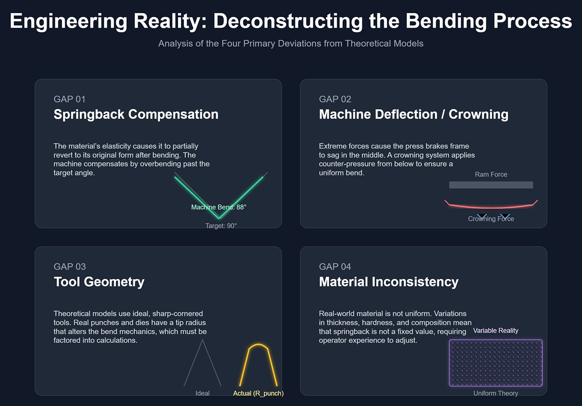
This is precisely where amateurs and professional engineers diverge. Theoretical formulas yield an ideal geometric depth suited for a laboratory vacuum, whereas the machine setting is the end result of multiple compensations accounting for the messy and complex realities of the physical world. At minimum, four significant gaps exist between the two:
First Gap: Springback Compensation
- This is the largest source of difference. As mentioned earlier, the machine must intentionally “overbend”. For example, theory might suggest that a 90° bend requires a Y-depth of 85.00 mm, but the controller, knowing from its database that this material springs back by 2°, will calculate the depth for an 88° bend (say, Y = 85.45 mm) and use that as the setting. You aim for 90°, but the machine actually bends to 88° in depth.
Second Gap: Machine Deflection Compensation / Crowning
- Under high bending forces, the ram and bed deflect slightly, like a wooden beam under load, causing a barely visible sag in the middle. This means that even if the Y-axis moves to 85.45 mm at both ends, the center may only reach 85.35 mm, resulting in a larger angle (more springback) in the middle of the workpiece.
- To address this, modern CNC press brakes feature a crowning system that creates a slight upward bulge in the center of the bed during bending, either hydraulically or mechanically. While calculating Y-axis depth, the CNC controller simultaneously determines the compensation tonnage or wedge position. The Y-value you see on the screen is merely a “nominal” figure—behind it lies a complex, dynamic compensation process.
Third Gap: Tool Geometry
- Theoretical models often assume infinitely sharp tooling, but in reality, all punches and dies have a tip radius (R_punch, R_die). This radius affects the bending geometry, the actual internal bend radius, and the resulting springback. A professional controller factors in the exact tool radius defined in your tool library to refine its calculations.
Fourth Gap: Material Inconsistency
- Theoretical calculations use “standard” values, but in practice, even within the same batch—or across different areas of the same sheet—thickness, hardness, and chemical composition can vary slightly. This means springback and the K-factor are not fixed. This is a gap beyond the reach of pure calculation and explains why later chapters will focus on “iterative corrections” and the invaluable role of operator experience.
III. Practical Blueprint: A Four-Step Method to Accurately Calculate and Set Bend Depth
From this point forward, forget the gut-feel “trial-and-error” method. We will replace craftsmanship guesswork with engineering precision. By following these four steps, you can transform bending from an unpredictable art into a predictable, repeatable science—turning theory into production power.
3.1 Preparation Phase: Data Collection Checklist to Ensure Accurate Inputs
The accuracy of your calculations depends entirely on the accuracy of your inputs. Before touching the calculator or control panel, perform this “precision ritual” to record the following information with forensic-level accuracy. Always remember the first rule of computer science: “Garbage In, Garbage Out.”
- [ ] Material Type: Identify exactly what you’re working with. Is it compliant mild steel, stubborn stainless steel, or lightweight, variable aluminum alloy? Their physical traits—springback behavior, ductility—differ greatly and dictate your compensation strategy.
- [ ] Actual Material Thickness (S): This is the most critical trap in the entire process. Never, ever use nominal thickness (for example, a “3 mm” plate might actually measure 2.91 mm or 3.05 mm). Use a micrometer to take multiple measurements at different points on the sheet and calculate the average. A 0.1 mm variation is enough to turn your 90° bend into 89° or 91°.
- [ ] V-Die Opening (V): Record the actual width of the V-opening in the lower die you’ll be using. Don’t just trust the markings on the tool—ensure it’s free from significant wear.
- [ ] Punch Radius (Rp): Note the tip radius of the punch. This parameter influences the actual internal bend radius and springback, and is a key variable in professional controller algorithms.
- [ ] Target Internal Angle (α): Define the final product angle you aim to achieve. This is the ultimate reference point for all calculations.
3.2 Core Calculation Procedure (with Example): From Theory to Practice
Let’s walk through a classic production scenario, tracing the complete thought process from blueprint to precise angle.
- Scenario: Using a standard press brake to bend a 3.0 mm actual thickness (S) mild steel sheet to a 90° internal angle (α).
3.2.1 Step One: Calculate the Ideal Bend Depth (No Springback Model)
First, we enter a pure “geometric vacuum,” unaffected by the laws of the physical world. Here, we calculate only the punch penetration depth (P) needed to achieve a 90° bend, temporarily ignoring springback—the “stubborn resistance” of the real world.
Die Selection: Before calculating, we apply one of the most important rules of thumb in sheet metal work—the “8× material thickness rule”—to choose the V-die. This gives us a solid, reliable starting point for our calculations.
- V = 3.0 mm × 8 = 24 mm. Therefore, for this task we select a lower die with a V-opening of 24 mm.
Calculation: This derives from the “bending triangle” geometric principle discussed in Chapter 2. For a target inside angle α, the punch penetration depth P can be calculated as:
To achieve a 90° outside angle, we need a 90° inside angle. Thus, the apex angle of the bending triangle is 180° − 90° = 90°. Substituting values:
→
Interim Conclusion: In a perfect world without springback, the punch must penetrate the die exactly 12.00 mm to form a flawless 90° angle geometrically. This is our theoretical baseline.
3.2.2 Step Two: Accounting for Springback to Determine the “Overbend” Target Depth
Now we leave the idealized geometric vacuum and return to the challenging reality of physics. For low-carbon steel bent with a 24 mm V-die, empirical data suggests a typical springback of about 1.5°. This means that if we bend exactly to 90°, it will relax to roughly 91.5° after releasing pressure.
Our strategy is to “work with it”: to achieve a finished 90° angle, we must first overbend to a sharper angle — i.e., 90° − 1.5° = 88.5° — and let it spring back to our target.
Now, with 88.5° as the new target, we recalculate the required penetration depth:
→
→
→
Correction: The correct formula uses tan((180 − α)/2), not α/2. Let’s recalculate:
→
→
→
Final Conclusion: To precisely counteract the 1.5° springback, we must lower the punch an additional 0.32 mm (12.32 − 12.00), resulting in a total penetration depth of 12.32 mm. This 12.32 mm is the practical target depth reference to program into the machine — no longer a purely geometric figure, but a “smart” number that factors in physical behavior.
3.2.3 Quick Start with the “Rule of Thumb”: When and How to Apply the “8× Material Thickness Principle” for Die Preselection and Depth Estimation
The guideline “V-opening ≈ 8 × material thickness” is the most widely used and practical golden rule in air bending. It’s not a rigid requirement, but a well-proven heuristic refined through extensive hands-on experience.
- What is it? It’s an empirical balance between bending force, inside bend radius, minimum flange length, and bending accuracy.
- Why 8? This number represents the art of engineering compromise.
- Less than 8× (e.g., 5–6×): The V-opening is too narrow. Advantage: a smaller inside radius, suitable for parts with special requirements. Drawbacks: required tonnage increases sharply, risk of fine cracks on the outside of the bend, and extreme sensitivity of angle to material thickness variations, reducing process stability.
- More than 8× (e.g., 10–12×): The V-opening is too wide. Advantage: significantly reduced tonnage, more suitable for thick plate and high-strength steels. Drawbacks: larger inside bend radius, less stable part positioning in the die, and potential for angle drift.
- How to use it? For any new job, the first step is to apply this rule to preselect the most suitable V-die. It gives you a reasonable, reliable starting point for all subsequent calculations. Note that for less ductile stainless steels, the factor is typically increased to 10×; for aluminum alloys, it can be reduced to around 6×. Think of it as a compass, not a GPS.
3.3 Digital Productivity Boost: Using Tools for Faster, More Accurate Calculations
Manual calculations deepen your understanding of the principles, but in the efficiency-driven reality of production, we must leverage tools so that human expertise can be focused on higher-level judgment and decision-making.
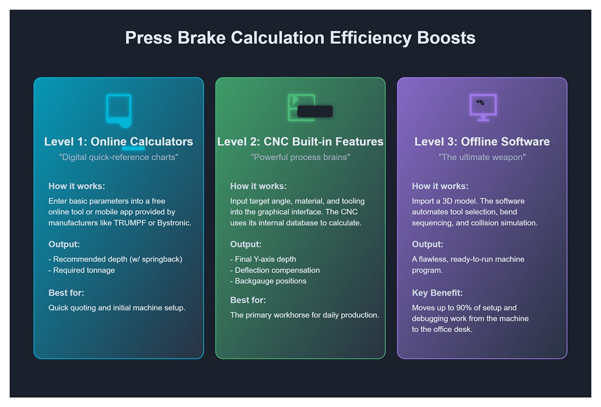
- Level 1 Boost: Online Bending Calculators / Mobile Apps
- These are your “digital quick-reference charts.” Many tooling manufacturers (e.g., TRUMPF, Bystronic, LVD) and software providers offer free online calculators. Simply enter the basic parameters, and within seconds you’ll get a recommended depth (including springback compensation) and required tonnage. Ideal for quick quoting and initial setup.
- Level 2 Boost: CNC Press Brake Built-in Calculation Features
- Modern CNC controllers are powerful process brains. In their graphical programming interface, you simply input the target angle, select the material and tooling, and the controller pulls from its extensive internal database (containing springback data and tooling geometry for hundreds of materials) to instantly calculate the final Y-axis depth, deflection compensation, and even backgauge positions. This is the primary workhorse tool for daily production.
- Level 3 Efficiency Boost: Offline Programming Software
- This is the ultimate weapon for achieving “first-piece perfection.” Software such as DELEM V-Bend, TRUMPF TruTops Bend, or BySoft Bending lets you import a part’s 3D model directly into your computer. It automatically unfolds the sheet, selects the optimal tools, plans the most efficient bending sequence, runs full 3D collision simulations, and finally outputs a flawless program ready to be transferred to the machine. In essence, it relocates up to 90% of setup and debugging work from costly machine-time to your office desk.
3.4 Verification and Fine-Tuning: The Closed-Loop Process from First Trial to Parameter Lock-In
Key Insight: No matter how precise a calculated value appears, when it is first applied to a particular batch of material, it is merely an “educated best guess.” The final truth must be established through direct interaction with physical reality—via trial bending and measurement. This closed-loop method is where professional operators deliver their true value.
- First Bend: Using the depth value generated from your calculations or software, perform the initial test bend on scrap material or a noncritical portion of a part from the same batch. This is your first “question” posed to the material.
- Precise Measurement: With a high-precision digital protractor or profile projector, measure the actual angle achieved. This is the material’s “answer” to your question. Suppose the measured angle is 90.5°, while your target was 90.0°.
- Fine-Tuning: This means your springback compensation was slightly excessive—the actual springback is less than predicted. In the CNC controller’s “Angle Correction” or “Y-Axis Fine Adjustment” interface, input a correction command. The process is straightforward: simply tell the controller, “The program target is 90.0°, but the actual result is 90.5°.”
- Second Bend & Lock-In: The controller, acting like an intelligent learning system, will automatically recalculate a shallower Y-axis depth (perhaps by +0.08 mm) and perform a second bend. If the measured angle now hits 90.0° precisely, immediately carry out the key step—‘save’ or ‘learn’ this corrected parameter within the controller.
Through this closed-loop cycle of calculate → test bend → measure → correct, you establish a physically verified, completely reliable set of process parameters for that specific material and tooling combination. From then on, all subsequent parts in the batch will be produced with stable, efficient, and repeatable precision.
IV. Advanced Mastery – Controlling Variables for Master-Level Precision
At this stage, you now have a scientific blueprint for bending. Yet between blueprint and real-world perfection lies a domain full of variables. The true difference between a skilled operator and a master lies not in the ability to draw a flawless plan, but in the ability to turn every deviation from that plan into a learning opportunity—transforming unpredictability into mastery. This is the art of controlling variables.
4.1 The “Iterative Correction Loop”: The Ultimate Practical Technique for Springback Control
Springback is the eternal opponent in sheet metal bending—and also its most honest teacher. Instead of resisting it, learn to listen and work with it. The “Iterative Correction Loop” is the structured language through which you and this teacher communicate. It transforms uncertain trial-and-error into a logical, fail-safe process.
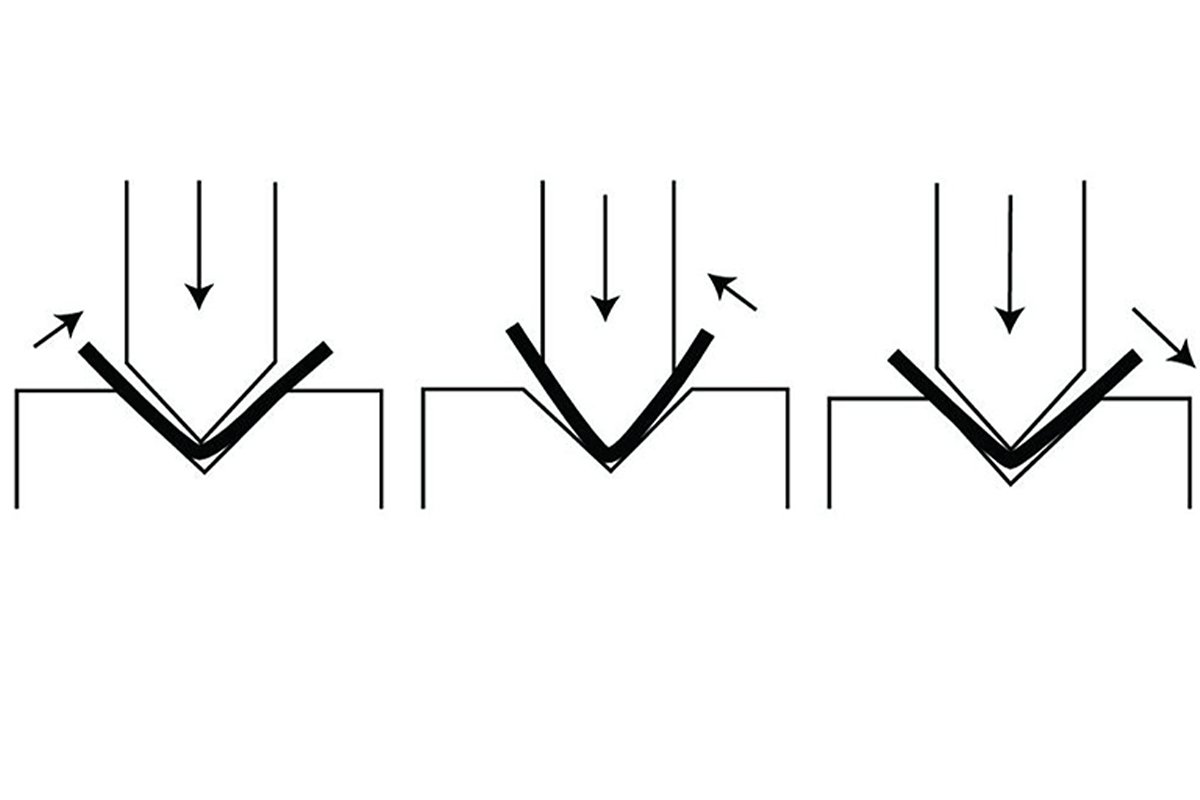
- Predict: Trust your system. Based on the CNC controller’s vast database or your offline programming software, set the initial bending depth for the first test. This is your data-driven, scientifically grounded “question” to the material.
- Execute: Respect physical reality. Perform the first test bend using a piece identical to the production part—same batch and rolling direction. This ensures an undisturbed and completely accurate testing environment for your “conversation.”
- Measure: Listen to the material’s feedback. Measure the actual angle after full pressure release and complete springback using a high-precision digital protractor. For example, your target is 90.0°, but the result is 91.2°. That reading is the material’s unbiased “response” to your initial question.
- Inform: This marks the shift from craftsmanship to engineering mastery. Abandon the instinct to “roughly deepen by 0.2 mm.” Your role now is to communicate facts, not guesses. In the CNC controller’s “Angle Correction” interface, input two undeniable values: “Actual angle = 91.2°” and “Target angle = 90.0°.” At this moment, you act as the machine’s sensory extension, transmitting the physical world’s truth directly to its digital intelligence.
- Correct: Witness machine intelligence at work. Once you hit “Confirm,” the controller—like a seasoned chess master—calculates instantly and precisely the Y-axis depth correction needed to eliminate the 1.2° deviation (perhaps –0.18 mm), generating a new, calibrated Y-axis coordinate.
- Confirm & Learn: Turn experience into an asset. Perform the second test bend at the new depth. In 99% of cases, the angle will now be perfectly within tolerance. Once verified, activate the controller’s critical “Learn” or “Save” function to lock in those results.
- Ultimate Meaning: Executing the “Learn” command is far more than saving a setting—it’s feeding your machine the most truthful, unique, and experiential data. With each learning cycle, you’re effectively training and upgrading your controller’s internal database. The next time you process the same material-tooling combination, it will recall this finely tuned knowledge to deliver near-perfect initial parameters. Each precise correction teaches your machine to understand you—and your materials—more deeply.
4.2 Material-Specific Optimization: Depth Adjustment Strategies for Stainless Steel, Aluminum Alloy, and High-Strength Steel
Different metals have distinct “personalities” and behaviors. Treating them all with a generic approach is the beginning of mediocrity. Master-level control starts with profound insight into—and respect for—each material’s unique character.
| Material | Main Challenges | Core Strategies for Advanced Adjustment |
|---|---|---|
| Stainless Steel | High and unstable springback; strong tendency toward work hardening. | 1. Increase V-die width: Abandon the traditional “8× material thickness rule” and move toward 10–12×. This isn’t merely to reduce tonnage—its core purpose is to achieve a larger internal radius, which helps moderate stainless steel’s stubborn springback, making it smoother, more stable, and easier to predict. 2. Increase over-bend allowance: Stainless steel exhibits far greater rebound than low-carbon steel, so the initial depth setting must be deeper to leave sufficient room for springback compensation. 3. Soften the bending process: Use slower bending speeds whenever possible. This effectively reduces work hardening, maintaining material consistency throughout the bend. |
| Aluminum Alloy | Poor ductility, high risk of cracking; delicate surface easily scratched. | 1. Increase punch radius (Rp): Avoid sharp punches entirely. A larger nose radius provides a gentler, more even tensile transition on the outer surface—like pressing with a palm instead of a fingertip—greatly reducing micro-crack formation. 2. Handle over-bending with caution: Aluminum’s springback is usually much smaller than steel’s, so excessive depth compensation can easily cause fractures. 3. Provide maximum surface protection: Cover the die opening with a polyurethane pad or thick protective film. This “soft armor” absorbs stress during contact, preventing any marks or scratches on expensive aluminum surfaces. |
| High-Strength Steel (HSS / AHSS) | Extreme springback (often 10°–20°); requires enormous tonnage. | 1. Maximize V-die width: Using 12–15× material thickness—or even wider—is often the only viable option to keep tonnage within machine limits. 2. Depend on robust deflection compensation: At these immense forces, deflection of the ram and bed becomes a primary factor, not a minor variable. A precise, powerful hydraulic or mechanical crowning system is the lifeline for achieving uniform bend angles across the full part length. 3. Mandatory use of real-time angle measurement systems: With springback so large and unpredictable, database-based estimates are unreliable. Real-time laser angle feedback transforms from luxury to necessity—the only path to efficient, high-accuracy production. |
4.3 The Hidden Power of Die Geometry: Leveraging Die Characteristics for Depth Optimization
To most operators, a die is a fixed, passive forming tool. But to a master, its very geometry functions as a set of adjustable controls—active parameters that can be fine-tuned to solve tricky physical problems.
- Hidden Power 1: Managing Springback Through V-Die Width
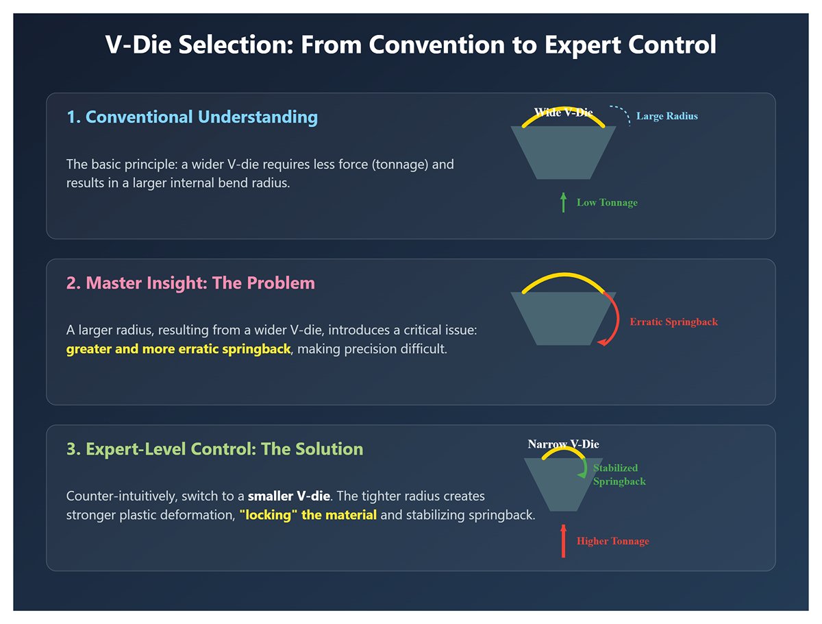
- Conventional Understanding: The wider the V-die, the lower the required tonnage and the larger the internal radius.
- Master Insight: The relationship between V-die width and springback is far from linear. For the same sheet thickness, a wider V-die yields a larger internal radius—and typically, a larger radius means greater and more erratic springback.
- Expert-Level Control: When dealing with materials whose springback variations make precise angles difficult to achieve, don’t just keep adjusting depth—think in reverse. Try switching to a smaller V-die. Yes, it will increase the required tonnage, but a tighter, smaller radius penetrates the material more deeply, producing stronger plastic deformation at the bend root. As a result, you effectively “lock” the material, drastically reducing and stabilizing springback for repeatable accuracy. In doing so, you move from passively compensating for a chaotic variable to actively making the variable itself controllable.
- Hidden Power 2: Exploiting Special V-Die Angles
- Beyond the common 85° and 88° V-dies, your toolkit should also include acute-angle dies, such as 30° or 45° versions.
- Advanced Usage: When bending short flange Z-shapes or deep U-channels, standard dies often cause fatal interference—the second bend’s short leg collides with the die’s broad sidewalls. Acute-angle dies, with their narrow and steep walls, provide critical clearance for these complex geometries. While the core calculation for depth remains unchanged, your process planning must include one more step: perform 3D offline simulation in your programming software to ensure the final bending depth prevents any collision between the workpiece and die walls.
4.4 Complex Process Analysis: Coordinating Depth in Multi-Bend, Z-Bend, and Hemming Operations
When a workpiece requires multiple bends, each operation ceases to be independent—they become an interconnected sequence of actions that influence one another. Depth control at this stage evolves into a holistic management of error propagation across the entire process chain.
- Multi-Bend Parts (e.g., boxes)
- Core Challenge: Error accumulation—the number one enemy of precision manufacturing. A mere 0.2 mm backgauge positioning error or a 0.3° angle deviation in the first bend carries through to subsequent bends, amplifying like a rolling snowball.
- Depth Coordination: The precision of the first bend is the unshakable foundation of all subsequent operations. You must invest whatever it takes to refine the first bend angle through iterative correction cycles until perfect. All later depth calculations must rely entirely on that flawless geometric baseline created by the initial fold.
- Z-Bends / Offset Bends
- Core Challenge: Maintaining two opposing bend surfaces perfectly parallel and ensuring exact offset height consistency.
- Depth Coordination: While the two bend depths are computed independently, the real difficulty lies in synchronizing their resulting angles. Even a small mismatch (for example, one bend at 90.5° and the other at 89.5°) transforms a precise rectangular cross-section into a trapezoid devoid of accuracy.
- Hemming
- This is a classic two-step process, and one that is often disastrously misunderstood.
- Step 1: Acute-Angle Pre-Bend. Use a sharp punch (such as a 30° tool) and a standard V-die to bend the sheet into a 28–30° acute angle. Depth calculation here follows normal air-bending principles, aiming solely to achieve a precise pre-bend angle.
- Step 2: Flattening. Switch to a dedicated flattening tool to compress the pre-bent section.
- “Overwhelming Cognitive Shift”—A Philosophical Change in Control Logic: *_The flattening stage is not governed by depth (Position) but by tonnage (Pressure).* In your CNC setup, the Y-axis value only defines the safe, gentle _approach point where the flattening tool makes contact with the workpiece. The real process begins once contact is made—the controller switches instantly to pressure mode, applying a precisely calibrated tonnage (for example, 20 tons) to compress the flange, then retracts immediately. If you attempt to control this with depth—say, by setting an excessively deep Y value to “press all the way down”—you’ll trigger an instant overload, risking permanent damage to both the tool and the machine ram. This marks a fundamental shift from position control to pressure control—the critical boundary separating professional precision from hazardous brute force.

V. Conclusion
In short, you now have the complete blueprint for mastering Press Brake Bend Depth Calculation, from the core physics to the expert techniques needed to conquer real-world variables like springback and deflection.
This same intelligence is engineered into every ADH Machine Tool press brake. To achieve this level of precision automatically, contact us. Let our expert systems handle the complex calculations, so you can focus on production. For more detailed specifications and capabilities, you can explore our Brochures to find the right solution for your operation.


