I. Introduction
For most people, a laser cutting machine is still instinctively defined as a piece of equipment that simply “cuts metal sheet.” Under the broader narrative of Industry 4.0 and smart manufacturing, this perception is now badly outdated. To truly understand and harness this technology, we must move beyond seeing it as a single-purpose tool and instead build a new mental model that treats it as a digital manufacturing hub. For a deeper understanding of the technology behind it, see CNC Laser Cutting Machines Explained.
If you are curious about how different power levels affect performance, check out Understanding Laser Cutting Machine Wattage: A Comprehensive Guide.
1.1 Redefinition: From Mechanical Stamping to a Revolution in Thermal Separation
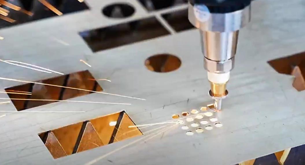
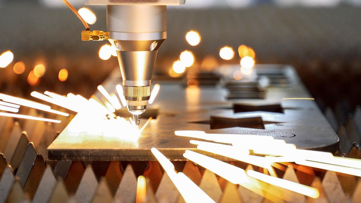
Essence Explained: A Microscopic Game Between Photons and Atoms Strictly speaking, laser cutting is not “mechanical cutting” in the traditional sense. Under the command of a CNC (computer numerical control) system, it is a process of precise thermal separation using a high–energy-density laser beam. When the beam is focused on a single point, the resulting energy density is sufficient to melt or vaporize the material in an instant. A high‑speed flow of assist gas then blows away the molten material, creating a clean separation gap. This is more than just a change in processing method; it is a fundamental shift in how energy is applied in manufacturing.
To understand how mechanical movement along different axes affects precision, see The X-Axis in Laser Cutting Machines.
Value Shift: The Physical Entry Gate to Industry 4.0 Why is it called the physical entry point to smart manufacturing? Because it provides the shortest path between “virtual design” and “physical product.”
- No-Mold Manufacturing: Unlike stamping, which relies on molds, laser cutting requires no tooling. It reads CAD drawings directly, compressing the time from design change to finished part down to the bare minimum.
- Flexible Production: It gives production lines exceptional flexibility. Whether for a one-off prototype or a batch of tens of thousands, switching between jobs is almost costless. This makes laser cutting a core asset for modern factories facing small-batch, high-mix, and customized orders.
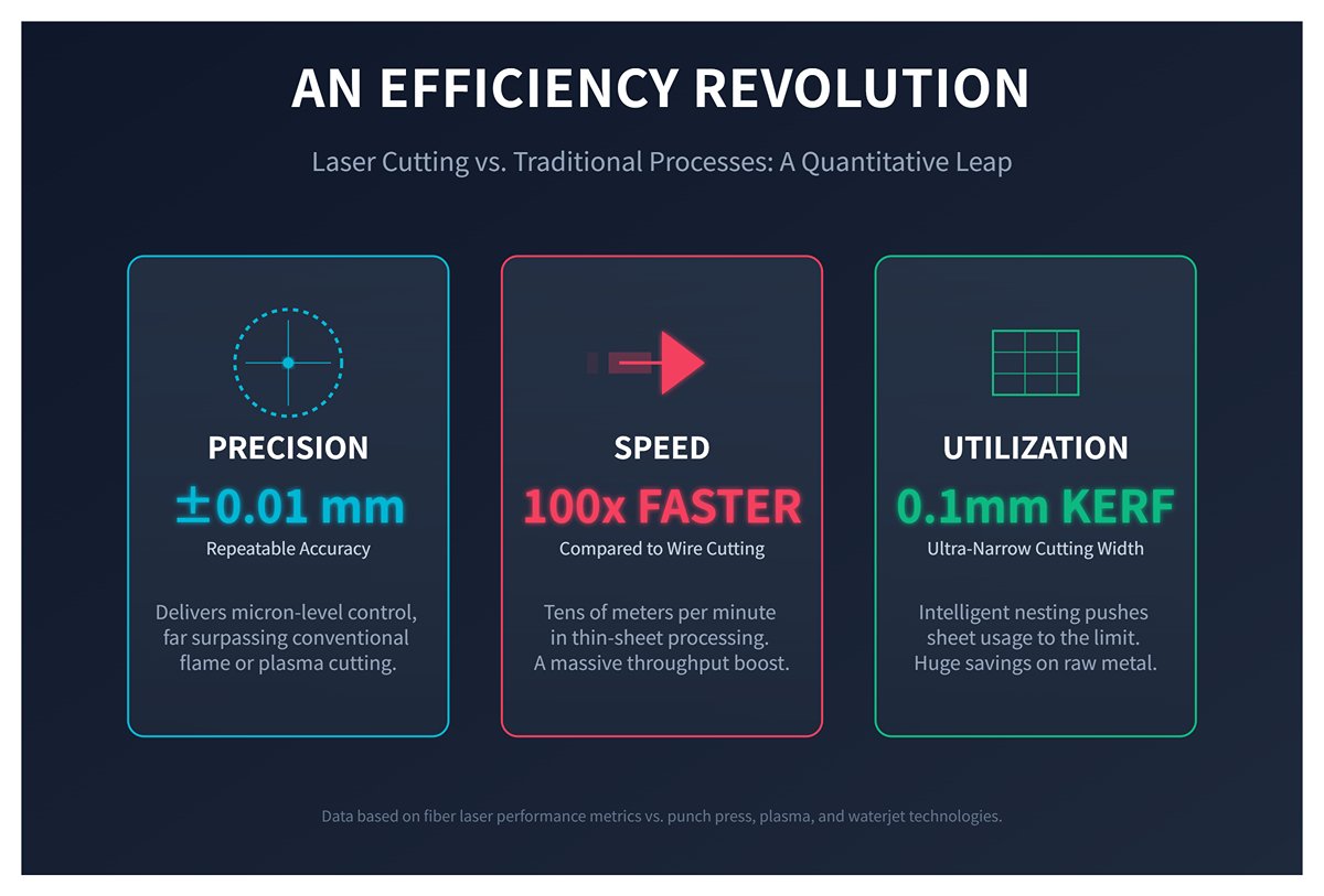
An Efficiency Revolution: A Step-Change Over Traditional Processes Quantitative comparisons clearly reveal how laser cutting outperforms punch presses, plasma, and waterjet technologies:
- Precision: It can achieve repeatable positioning accuracy of ±0.01 mm, delivering micron-level control far beyond the reach of conventional flame or plasma cutting.
- Speed: In thin-sheet processing, fiber lasers can reach cutting speeds of tens of meters per minute, making them dozens or even hundreds of times faster than wire cutting.
- Material Utilization: Thanks to an ultra-narrow kerf of just 0.1–0.3 mm, combined with intelligent nesting software, sheet utilization can be pushed to the limit. For high-value metals, the cost savings from material alone are often substantial.
To better grasp how these systems achieve such precision, check out CNC Laser Cutting Machines Explained.
1.2 Decision-Maker Profiles: Who Sees What Value?
Different decision-makers looking at the same machine should perceive completely different value maps:
For Business Owners (CEO/Owner): A Cash-Flow Accelerator Do not classify a laser cutting machine merely as a fixed-asset purchase. In essence, it is a tool for optimizing capacity and cash-flow turnover.
- Faster delivery cycles translate directly into faster cash collection.
- Lower defect rates convert directly into higher net profit.
- The machine can handle high–value-added precision jobs, fundamentally upgrading the company’s profit structure.
For Engineers (R&D/Design/Process): Unlocking Design Freedom On the design side, laser cutting represents a major expansion of the boundaries of DFM (Design for Manufacturability). For inspiration on design optimizations and related use cases, you can explore Laser Cutting Machines and Applications.
- Geometric Freedom: You can design virtually any 2D contour without worrying about tool radius or mold constraints.
- Structural Optimization: High precision enables common-line cutting, micro-joints, and even carefully designed interlocking features that can replace downstream welding operations.
For Procurement Managers: Seeing Through to TCO A capable buyer must be able to see beyond the quotation sheet and understand the TCO (Total Cost of Ownership) behind the spec sheet.
- Beware of the Low-Price Trap: The initial purchase price typically accounts for only about 30% of the total lifecycle cost.
- Focus on Hidden Costs: Photoelectric conversion efficiency (electricity cost), consumable component life (consumables cost), and downtime due to failures (opportunity cost) are the real variables that determine ROI (return on investment).
For a strategic overview of cost-efficiency and lifecycle performance, read Strategic Insights into Fiber Laser Cutting.
1.3 Market Overview: Reading Technology Iteration in a Multi-Billion-Dollar Sector
Data Insight: An Irreversible Growth Trajectory According to authoritative market forecasts, the global laser cutting machine market is expected to grow from about USD 6.9 billion in 2025 to USD 14.3 billion by 2035. This near-doubling reflects the rigid global demand for upgrading from “rough machining” to “precision manufacturing.” North America alone accounts for over 30% of the global market, signaling an imminent wave of equipment upgrades in this high-end installed base.
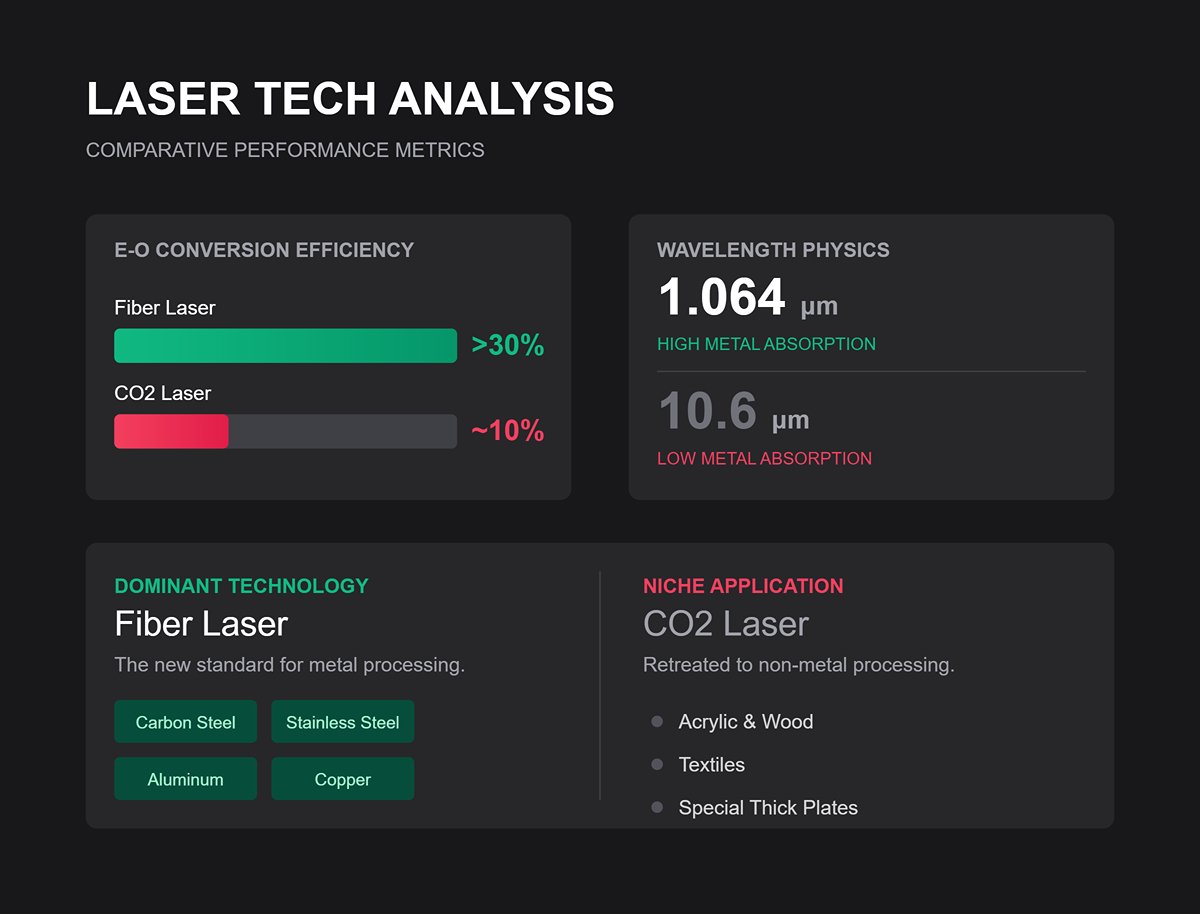
Technology Watershed: Fiber Laser’s Complete Dominance If the past decade was a contest between CO2 and fiber lasers, the outcome is now clear.
- Fiber Lasers: With a wavelength of 1.064 μm, fiber lasers are absorbed very efficiently by metals (especially carbon steel, stainless steel, aluminum, and copper). Coupled with an electro‑optical conversion efficiency above 30% (compared with roughly 10% for CO2), fiber lasers have fully displaced CO2 systems as the new standard in metal processing.
- CO2 Lasers in Retreat: Due to their 10.6 μm wavelength, CO2 lasers have largely retreated to niches such as non-metal processing (acrylic, wood, textiles) and certain special thick-plate applications.
Once this cognitive reframing is in place, you effectively hold the key to advanced manufacturing. Next, we will dive beneath the surface of the machine itself and dissect its internal architecture with surgical precision.
II. Fundamentals of Laser Cutting Machines
1. Definition of Laser Cutting Machines
A laser cutting machine is a device that uses a high-power-density laser beam to cut, engrave, and drill materials. By precisely controlling the trajectory of the laser beam, it melts, vaporizes, or ablates both metallic and nonmetallic materials to achieve high-precision, high-efficiency cutting. It offers advantages such as non-contact processing, exceptional precision, broad applicability, and seamless integration with automated systems. If you’re seeking a more efficient cutting solution, consider exploring the Double Table Fiber Laser Cutting Machine.
2. Working Principle of Laser Cutting Machines
The core principle of laser cutting machines lies in utilizing a high-energy-density laser beam to heat materials, causing them to melt or vaporize. Through precise control of the cutting path, the machine achieves accurate material separation.
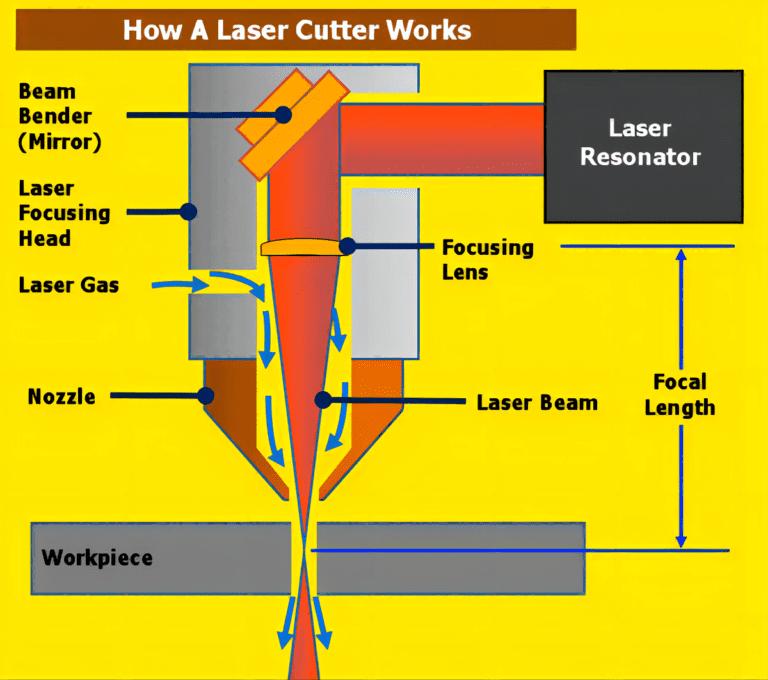
(1) Laser Generation
At the heart of the system is the laser generator, which produces a high-energy, highly focused laser beam using a specific medium (such as CO₂, fiber, or solid-state lasers). The laser is generated by an external pump source (like electrical current or gas), which excites the active medium to emit coherent photons, forming the laser beam.
(2) Laser Focusing
After generation, the laser beam is directed through an optical system—lenses and mirrors—to focus it to a minuscule point, creating an intense heat source on the material’s surface. This focusing process, typically handled by the optics in the cutting head, is key to achieving the required power density.
(3) Cutting
The focused laser beam strikes the material’s surface, and due to its immense energy density, heats the material to its melting or boiling point—sometimes even vaporizing it instantly. The interaction varies depending on the material:
- For low-melting-point materials (like plastics), the laser melts the material to form a cut.
- For high-melting-point materials (like metals), it vaporizes the material, producing a narrow slit.
- In certain cases, the laser induces chemical reactions such as oxidation or combustion.

(4) Gas Assistance
During the cutting process, auxiliary gases (such as nitrogen or oxygen) are often blown onto the cut to remove molten or vaporized material and cool the cutting area, preventing burrs or slag formation. The use of assist gases is vital for enhancing both cut quality and efficiency.
(5) Cutting Path Control
Laser cutting machines are typically governed by a CNC (Computer Numerical Control) system, which precisely guides the laser beam along pre-programmed shapes and paths. By adjusting parameters such as cutting speed, laser power, and focal distance, operators can control the width, taper, and quality of the cut.
3. Cutting Methods
(1) Fusion Cutting
Fusion cutting is widely used for metals such as stainless steel and aluminum alloys. The principle involves using a laser to locally melt the material, creating a molten pool, while a coaxial jet of high-pressure inert gas (such as nitrogen) blows away the molten metal to form a kerf.
This process requires inert gas—most commonly nitrogen—to prevent oxidation and produce a bright, oxide-free cutting surface, which is ideal for subsequent welding or coating processes. The main advantages are high edge quality, smooth surfaces, and excellent corrosion resistance; however, it demands high laser power and gas pressure (typically 10–20 Bar), resulting in higher operating costs.
(2) Vaporization Cutting
Vaporization cutting relies on extremely high power densities (>10⁸ W/cm²) to instantly convert the material from solid to gas, enabling “chip-free” processing.
The material rapidly vaporizes into plasma vapor, which is expelled at high speed, producing almost no slag. This method offers the highest cutting quality, exceptionally smooth edges, and the smallest heat-affected zone; however, it is slow and highly energy-intensive.
As a result, vaporization cutting is primarily used for non-metallic materials, metal foils, and precision microfabrication, and is rarely applied in conventional metal plate processing.
(3) Flame Oxidation Cutting
Flame oxidation cutting (also known as oxygen cutting) is mainly employed for carbon steel and other easily oxidized materials. The laser heats the material to its ignition point, and a coaxial stream of oxygen reacts exothermically with the hot metal. This reaction provides the primary energy for cutting, with the laser acting mainly as an “igniter” while the oxygen jet removes the resulting oxide slag.
High-purity oxygen must be used, though the required gas pressure is relatively low (typically 1–4 Bar). The advantages are fast cutting speeds (especially for thick plates), lower laser power requirements, and reduced gas costs. The drawbacks include the formation of a black or dark gray oxide layer on the cut surface, rougher edges, and a larger heat-affected zone. The oxide layer must be removed before any subsequent welding or coating. This method is not suitable for stainless steel or aluminum alloys.
4. Major Types
(1) Classification by Laser Source
1)CO₂ Laser Cutting Machines
These employ a mixture of carbon dioxide gases as the working medium, emitting laser light through gas discharge. The focused laser spot melts or vaporizes the material, while assist gases blow away the slag, completing the cut. The typical wavelength is 10.6μm, which is well absorbed by nonmetallic materials.
CO₂ systems have a lower purchase price than fiber lasers, but their photoelectric conversion efficiency is only about 10–15%. They require regular replacement of laser gases, as well as maintenance and calibration of mirrors, resulting in higher running costs.
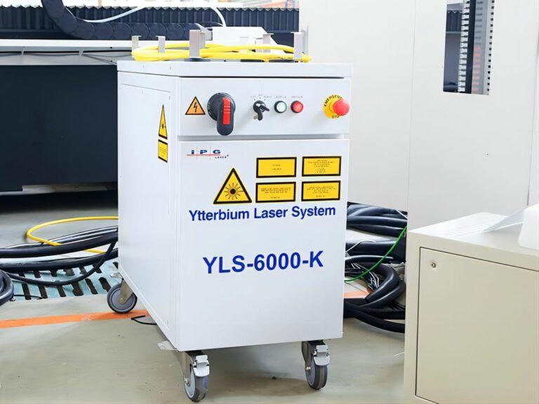
2)Fiber Laser Cutting Machines
These use optical fibers doped with rare earth elements (like ytterbium) as the gain medium. Semiconductor pumping generates the laser, which is focused into an ultra-high-energy-density spot to instantly melt metals, with high-pressure assist gas blowing away the molten material for precise cuts. The typical wavelength is 1.06μm, which is readily absorbed by metals.
Although fiber lasers have a higher initial cost, their photoelectric conversion efficiency usually exceeds 30% and can reach up to 50%. They require no laser gases, the optical path is maintenance-free, and their energy consumption is lower, resulting in reduced operational and maintenance costs.
3)Solid-State Laser Cutting Machines
Nd: YAG Laser Cutting Machine:
An early solid-state laser technology utilizing neodymium-doped yttrium aluminum garnet crystals as the gain medium, with a wavelength of 1.064μm. Historically used for metal marking and thin-sheet cutting, but due to lower efficiency, beam quality, and reliability compared to modern fiber lasers, it is being phased out.
Disk Laser Cutting Machine:
Employs thin, disk-shaped crystals (such as Yb:YAG) as the gain medium, with a wavelength around 1.03μm. This design combines the excellent beam quality of CO₂ lasers with the metal-cutting advantages of fiber lasers, but is complex and costly, with a smaller market share.
For buying decisions, refer to the table below:
| Laser Type | Typical Wavelength (μm) | Main Advantages | Main Disadvantages |
|---|---|---|---|
| CO2 Laser | 10.6 | Suitable wavelength for most material absorption, excellent cutting performance, high power, stable beam | Large size, high energy consumption, complex thermal management, longer wavelength limits cutting of certain materials |
| Fiber Laser | 1.06 | Fast heat dissipation, maintenance-free, vibration-resistant, compact size, low energy consumption | Limited capability for processing non-metallic materials |
| Nd: YAG Solid-State Laser | 1.064 | High gain, low threshold, suitable for high repetition rate and large pulse energy applications | Requires effective cooling, complex system, relatively large size |
| Disk Laser | 1.03~1.06 | Excellent beam quality, high conversion efficiency, effective cooling, suitable for high power applications | High cost, complex structure |
Fiber lasers offer significant advantages in speed, energy efficiency, and maintenance, especially for mass metal sheet processing, dramatically increasing productivity for thin and medium plates. Their main drawback is the higher initial investment, though costs have dropped considerably in recent years.
However, fiber lasers are less suited to nonmetals—users needing to cut wood, acrylic, or textiles may still require CO₂ technology. Nevertheless, the advantages of fiber lasers position them as the leading choice for industrial sheet metal cutting in 2025 and beyond.
(2) Classification by Mechanical Structure
1)Gantry-Type Laser Cutting Machine
The crossbeam is supported at both ends by parallel rails, providing excellent rigidity. It’s suitable for large-format, high-precision, and heavy-duty cutting.
2)Cantilever-Type Laser Cutting Machine
The crossbeam is supported at only one end, resulting in a compact structure and small footprint—ideal for medium-format processing or space-constrained environments.
3)Hybrid-Drive Laser Cutting Machine
An optimized version of the gantry type, key improvements include an independent X-axis drive system for the cutting head, separated from the Y-axis movement of the crossbeam.
| Requirement | Recommended Structure Type | Key Reason |
|---|---|---|
| Large Format / Heavy Load / High Precision | Gantry Type | High rigidity, large format, and high precision, suitable for large-scale and heavy-duty processing. |
| Limited Space / Medium-Small Format | Cantilever Type | Space-saving, high flexibility, suitable for small-scale and diverse orders. |
| Multi-process / High Efficiency / High-end | Hybrid Drive Type | High precision and efficiency, ideal for complex and diversified production needs. |
III. Key Components of a Laser Cutting Machine
1. Laser Generator
The laser generator is the heart of a laser cutting machine, producing the high-energy laser beam. It converts electrical or alternative energy sources (such as chemical reactions or gas discharge) into laser energy. Common types include:
(1) Fiber Laser
Energy from the pump source is injected into a fiber doped with rare earth elements, where population inversion and stimulated emission in the optical resonator amplify the photons, generating a high-power, highly directional laser beam.
This is the mainstream technology in metalworking today, with a wavelength of approximately 1.06μm, making it ideal for cutting carbon steel, stainless steel, aluminum, copper, and other metals.
(2) CO₂ Laser
Electrically excites a gas mixture, relying on population inversion and stimulated emission within a resonator to amplify photons and produce a high-power, highly directional laser.
With a wavelength of about 10.6μm, this mature technology remains essential for nonmetal cutting applications.
(3) YAG Laser
YAG lasers use neodymium-doped yttrium aluminum garnet crystals, excited by a pump source to generate laser light.
With a wavelength of roughly 1.06μm, they are suitable for cutting thick metals but are more expensive and have shorter service lives.
Other types, such as semiconductor and liquid lasers, are mostly used in medical or scientific research and are rare in industrial settings.
2. Optical Path System
Laser cutting machines often use a flying optical path system: after the laser is emitted, it’s reflected through a series of mirrors and finally focused by a lens onto the cutting head for material processing. Key elements include:
| Component | Main Function | Features |
|---|---|---|
| Mirror | Changes the laser propagation direction. | Typically has three sides (A, B, C), each mounted on adjustable brackets for precise alignment of the optical path. |
| Beam Expander | Adjusts the laser beam diameter and improves beam quality. | Not included in all systems; primarily used for optimizing the beam to achieve better cutting performance. |
| Focusing Lens | Focuses the laser beam into a small, high-energy-density spot. | A key component for achieving high energy density necessary for efficient cutting. |
| Optical Transmission Structure | Guides the laser from the laser source to the cutting head with stability and precision. | In conventional (non-fiber) cutting machines, the optical path is constructed using multiple mirrors set at 45-degree angles. |
Fiber laser machines transmit the beam via fiber optics; the system comprises a high-power laser, delivery fiber, and the laser head. Cutting stability and quality depend on the precise coordination between the fiber and the head.
3. Cutting Head
The laser cutting head—often referred to as the "laser torch"—is a precision module integrating optics, mechanics, and sensors.
Mounted on the X-Y motion system, it can move rapidly across the work surface, while the Z axis precisely adjusts the nozzle-to-material distance. This three-axis coordination enables intricate shape cutting.
The cutting head’s core features include:

(1) Nozzle
It directs auxiliary gases (such as oxygen or nitrogen) coaxially with the laser beam into the kerf. The gases serve two main purposes: blowing molten metal from the cut and shielding the focus lens from debris. When cutting materials like carbon steel, oxygen can also chemically react with the metal, boosting cutting efficiency.
(2) Height Sensing System
For optimal results, the head must maintain a precise, constant distance from the metal surface. Typically, a capacitive sensor is integrated to provide real-time feedback and automatic Z-axis adjustment, ensuring stable cut quality.
(3) Protective Lens
To safeguard the expensive focusing lens, the head is fitted with a replaceable protective lens—this consumable is the first line of defense against spatter and must be replaced regularly.
4. Machine Bed
The bed forms the foundation of a laser cutting machine, supporting motors, rails, the cutting head, laser optics, and more—ensuring secure mounting and precise movements. Main types include:
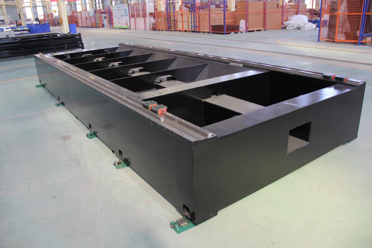
(1) Gantry Bed
The most prevalent structure, featuring a sturdy base (fixed table or platform) and a movable gantry spanning it. The cutting head is mounted on the crossbeam (Y-axis), the gantry moves along the base (X-axis), and the head traverses the crossbeam (Y-axis).
This fully enclosed design offers high rigidity, precision, and customizable size, making it suitable for large-format cutting tasks.
Constructed from box-type or frame steel, it withstands heavy cutting forces and vibrations, ensuring process stability.
(2) Cantilever Bed
An open structure where the table is fixed (or movable) and the cutting head is mounted on a cantilever beam supported from one side. The beam moves along the table (X-axis), and the head moves across the beam (Y-axis).
This setup facilitates easy loading/unloading and is ideal for standard-format sheet cutting, offering flexibility and lightness for small to medium workpieces.
Cantilever beds are typically made from high-strength cast iron or optimized cast structures; premium versions may feature marble or enhanced cast bases for long-term accuracy.
(3) Fully Enclosed Bed
Primarily used in high-power laser machines (e.g., 15,000W and above), this structure minimizes dust and fumes while providing an optimal cutting environment. These beds are made from heavy-duty steel, welded and heat-treated multiple times for superior rigidity and stability.
There are many other bed types; for more information, see How Laser Cutting Machine Work.

5. CNC System
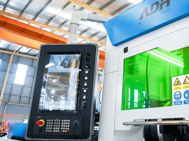
The CNC (Computer Numerical Control) system is the "brain" of the laser cutting machine, comprising a controller (industrial PC or PLC) and specialized software. It interprets cutting programs (G-code or dedicated CAD/CAM instructions), coordinating machine movement and laser operation.
It precisely controls the movement of the cutting head along the X, Y (and sometimes Z) axes, activating the laser according to the programmed geometry.
The CNC provides an operator interface for loading part designs, setting parameters, and monitoring status. High-end machines offer integrated cutting parameter libraries, real-time monitoring, and automation interfaces—all managed by the control system to guarantee precise cutting of complex contours, sharp corners, and small holes.
Operating a CNC system involves many critical considerations; for detailed procedures, refer to Laser Cutting Machine Procedures.
6. Motors
The motors in a laser cutting machine are responsible for driving the movement of the laser head. The main types include:
| Motor Type | Characteristics | Suitable Scenarios |
| Stepper Motor | Fast starting speed, responsive, suitable for applications with lower cutting precision requirements. | Low-end or entry-level laser cutting machines, industries and products with low cutting requirements. |
| Relatively low cost. | ||
| Servo Motor | High mobility, smooth movement, strong load capacity, stable performance. | Industries requiring high cutting precision and speed, such as metal processing. |
| Enables high-speed and smooth motion of the laser head, producing smooth cutting edges and fast cutting speed. | ||
| Supports intelligent management, capable of automatic parameter adjustment, enhancing operational stability and efficiency. | ||
| Linear Motor | Directly drives the laser cutting head along a straight line, eliminating intermediate traditional mechanical transmission. | High precision, high-speed cutting requirements, widely used in fiber laser cutting machines. |
| High acceleration, high speed, high positioning accuracy. |
1_w1200_w1200.jpg)
7. Auxiliary Gas System
Auxiliary systems include the gas circuit, gas supply, and dust removal systems. They provide the necessary auxiliary gases (such as nitrogen or oxygen) for cutting and collect dust and debris produced during the cutting process. These systems ensure the safety and environmental friendliness of the cutting operation.
(1) Auxiliary Gas Supply System
Modern laser cutting machines typically integrate the auxiliary gas supply system with the CNC system, allowing automatic adjustment of gas flow and pressure to optimize the cutting process. High-pressure gas nozzles precisely deliver auxiliary gas to the cutting point, removing molten material, keeping the cutting area clean, cooling the material, and preventing deformation. Different gases offer different cutting effects:
| Gas Type | Function and Characteristics | Applicable Materials and Effects |
|---|---|---|
| Nitrogen (N₂) | Inert gas that prevents oxidation, ensures bright and color-free cuts; suitable for high-quality cutting. Reduces costs, increases cutting speed, and improves productivity. | Stainless steel, aluminum, and materials requiring high-quality cutting. |
| Oxygen (O₂) | Reactive gas that supports combustion and generates exothermic reactions, enhancing cutting speed and efficiency. However, it may cause oxidation and carbide layers, affecting surface quality. | Carbon steel and thicker materials; suitable for applications not sensitive to edge oxidation. |
| Compressed Air | Cost-effective, contains about 21% oxygen. Cutting speed and efficiency are between nitrogen and oxygen. Cuts may have oxidation and burrs, suitable for parts without strict requirements on cut color. | General metal cutting, ideal for products with post-processing deburring steps. |
(2) Cooling System
Laser cutting machines generate significant heat during operation, especially high-power lasers. If this heat is not dissipated promptly, it can lead to overheating and damage to the laser, optical components, and other critical parts.
Thus, the cooling system is essential in a laser cutting machine, preventing overheating and ensuring the laser works within optimal temperature ranges, thereby improving cutting efficiency and accuracy.
Cooling systems are generally divided into water-cooling and air-cooling types. Air-cooling uses fans to force airflow over heat sinks or radiators, offering a lower cost but limited cooling capacity, making it suitable primarily for low-power machines.

Water-cooling systems provide much stronger heat dissipation and are essential for high-power lasers. They typically consist of the following components:
| Component | Function |
|---|---|
| Chiller | Core component of the water cooling system, responsible for heating cooling water and releasing heat to the external environment through a heat exchanger. |
| Cooling Water Circulation Pipeline | Transports cooling water to key components such as lasers and optical elements, removes heat, and returns to the chiller for circulation. |
| Radiator | Releases heat from the cooling water into the external environment, typically installed outside the chiller or laser cutting machine. |
| Water Tank and Filter | Stores cooling water and filters impurities in the water to prevent radiator blockage. |
| Temperature Sensor | Monitors the temperature of the laser and feeds temperature signals back to the control system to adjust the cooling system's operating state. |
(3) Fume Extraction and Dust Removal System
Laser cutting generates large amounts of fumes and harmful gases, which can harm operators’ health and corrode equipment. The dust removal and extraction system mainly involves smoke collection, purification, and discharge.
Smoke collection captures fumes at the source via hoods and ducts. For instance, blowers direct fumes through ducts to a moving suction trolley, which then transfers them to the dust collector.
Smoke purification occurs inside the dust collector, where multiple filtration stages—such as high-efficiency filters and dust collectors—remove particles of varying sizes. These multi-stage systems help ensure factory air quality meets environmental standards.
Smoke discharge refers to releasing purified air outdoors via exhaust systems, keeping the workshop air clean and fresh.

(4) Safety Protection System
The safety protection system includes four core components:
1)Protective Covers and Shields: Laser cutters are usually equipped with transparent or semi-transparent covers to block direct laser radiation and flying metal debris and fumes, protecting operators.
2)Enclosed Protection System: Modern machines use sealed protection to create a fully or partially enclosed chamber, preventing laser leakage and harmful fume escape, while still allowing for efficient loading and unloading of workpieces, thereby increasing productivity and reducing risks.
3)Safety Interlock Switches: Protective covers typically feature interlocks, so the machine will only operate when the safety shield is properly installed, reducing the risk of laser leakage accidents.
4)Emergency Stop Button: The machine features an emergency stop button which, when pressed, instantly cuts off the laser and power supply to prevent accidents and ensure operator safety.
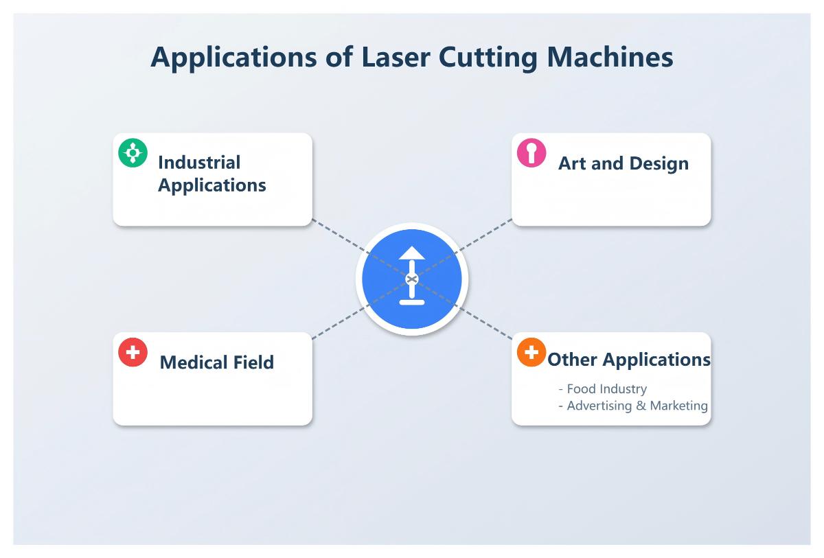
Ⅳ. Applications of Laser Cutting Machines
1. Industrial Applications
(1) Sheet Metal Fabrication
Laser cutting machines are widely used in processing sheet metal parts such as automotive components, appliance housings, and industrial equipment enclosures. Their precise cutting capability ensures consistent dimensions and high quality.
(2) Aerospace Industry
In aerospace, laser cutters are used to process high-strength alloys and composites for aircraft structures, turbine blades, and other precision components.
(3) Electronics Industry
Electronic device casings and brackets require extremely precise fabrication. Laser cutting meets these demands while minimizing heat-affected zones and protecting sensitive components.
(4) Architecture and Decoration
Laser cutting plays a key role in producing metal curtain walls, railings, and decorative panels, enabling high-quality and complex design solutions.
2. Art and Design
(1) Customized Products
Laser cutters are used to produce personalized jewelry, furniture, gifts, and more, such as engraving names, patterns, or intricate decorative details.
(2) Art Installations
Many artists use laser cutting to create sculptures, wall art, and lighting installations, showcasing unique visual effects.
(3) Textile and Fabric Design
In fashion, laser cutting enables the creation of intricate patterns, integrating innovative designs into clothing and textiles.
3. Medical Field
(1) Medical Device Manufacturing
Laser cutters are used to produce surgical instruments, precision catheters, and other medical equipment components that require high accuracy and smooth, safe edges.
(2) Implant Processing
Items such as cardiac stents and bone implants often require complex geometries, which can be achieved with laser cutting.
(3) Laboratory Tool Production
Laser technology is used to process thin films, micro-sieves, and other precision instruments for laboratory applications.
4. Other Applications
(1) Food Industry
Laser cutting is used for food decoration, such as precision cutting of icing, chocolate, and other decorative materials.
(2) Advertising and Marketing
It is employed to produce signs, display stands, and promotional installations, enabling high-quality, personalized customization.
Ⅴ. Advantages and Limitations of Laser Cutting Machines
1. Key Advantages
(1) Precision and Quality
Laser cutters achieve extremely high cutting accuracy—often at the micron level. Typical precision ranges for different laser types are:
- Fiber laser cutters: generally within ±0.03mm
- CO2 laser cutters: generally within ±0.05mm
Laser cutting produces narrow kerf widths (as small as 0.1mm), smooth, burr-free edges, a small heat-affected zone, minimal material distortion, and excellent cutting quality—ideal for direct further processing or assembly. The laser’s high focus and CNC-controlled path ensure top-notch results.
(2) Flexibility and Non-Contact Processing
Laser cutting is a digital process driven directly by CAD/CAM software. Operators simply import or draw designs in the software to start production, eliminating the need for costly physical molds. This provides tremendous flexibility and cost-effectiveness for small-batch, multi-variety, or customized manufacturing.
Moreover, as a non-contact process, there is no physical tool-workpiece contact, avoiding tool wear and preventing deformation due to mechanical stress—especially advantageous for thin, brittle, or easily deformed materials.
(3) Processing Efficiency
Laser cutting is especially fast for thin materials. Fiber lasers, in particular, are much more efficient than CO2 lasers for certain tasks. Reference data is as follows:
| Parameter | Stainless Steel | Stainless Steel | Aluminum Plate | Aluminum Plate |
|---|---|---|---|---|
| Thickness (mm) | 10 | 10 | 5 | 10 |
| Gas Type | O2 | N2 | N2 | N2 |
| Power (kW) | 5 | 5 | 5 | 5 |
| Cutting Speed (mm/min) | 680 | 1200 | 7000 | 2400 |
| Gas Pressure | 10.5 | 12 | 15 | 15 |
| Focus (mm) | -3 | -7.2 | -1.1 | -2.4 |
| Spacing (mm) | 0.6 | 0.6 | 0.6 | 0.6 |
| Nozzle Diameter (mm) | 2.5 | 3 | 2.5 | 3 |
| Frequency (Hz) | 5000 | 5000 | 5000 | 5000 |
To learn more about the technical specifications when selecting a laser cutting machine, you can download our Brochures.
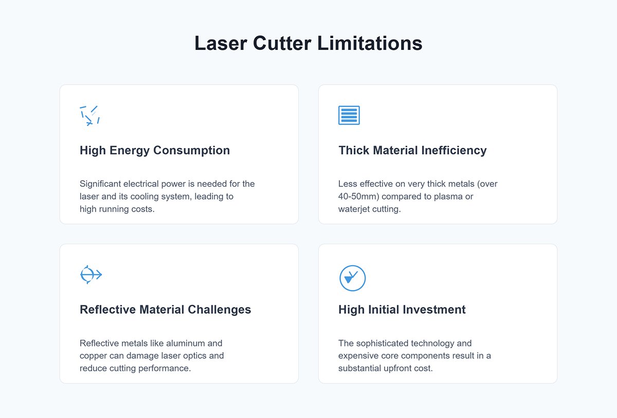
2. Limitations
(1) High Energy Consumption
Laser cutters require significant electrical power, especially high-power models. Despite their high efficiency, prolonged use can result in substantial electricity costs. Additional energy is also needed to run the cooling systems to maintain stable operation.
(2) Limitations in Thick Plate Cutting
While laser cutters excel at processing thin and medium-thickness sheets, they are less effective on very thick metals (such as carbon steel over 40-50mm) compared to other techniques like plasma or waterjet cutting. Materials with high thermal conductivity can further limit cutting performance.
(3) Reflective Material Challenges
Highly reflective metals (such as aluminum, copper, and silver) can reflect the laser beam, causing energy loss and potentially damaging laser optics. Although modern machines have mitigated this issue, the material’s characteristics still need careful consideration.
(4) High Initial Investment Costs
The initial investment required for a laser cutting machine is considerably high. This is largely due to its sophisticated technology, the expensive core components, and the performance configurations necessary to meet diverse industrial demands. The substantial upfront cost is primarily reflected in the following key areas:
For a detailed breakdown and specific model pricing, explore our comprehensive Laser Cutting Machine Pricing Guide.
3. Selection in Practice: A Methodology for Precise Decisions Without Parameter Anxiety
When faced with dense spec sheets and wildly different price quotes, many buyers slip into “parameter anxiety”: Is higher power always better? Does a higher price guarantee more stability? The answer is no. Blindly chasing top specs often leads to idle capital, while focusing only on low price can plant long-term maintenance landmines. This chapter presents a field-tested selection model to help you find the true sweet spot between budget and actual needs.
3.1 The Four-Quadrant Demand Matching Method
Before going any further, put the quotations aside and run a “four-quadrant checkup” on your own production model. This is not only the foundation for choosing the right machine—it’s also the prerequisite for clarifying your return on investment (ROI).
- Material Dimension: Build a “Material–Thickness–Reflectivity” Triangle This is the primary factor that sets the laser source type and minimum power. Start by identifying your core materials: if you mainly process carbon steel and stainless steel, a fiber laser is the default choice. If you work extensively with high-reflective materials such as copper, gold, or silver, you must confirm that the laser has anti-reflection protection; otherwise, reflected light can cause irreversible damage to the source. Next, size power based on “the maximum thickness of the 80% core workload,” not the “occasional extreme thickness.” For example, if 90% of your parts are ≤20 mm and you only occasionally cut 25 mm, 12 kW is more than enough. There’s no need to jump to 20 kW for that 1% of jobs—outsourcing those rare cuts is usually more economical.
- Precision Dimension: Distinguish Between Contour Cutting and Precision Machining Don’t pay for accuracy you will never use. For industries such as agricultural machinery or steel structures that only require contour cutting, a repeatability of ±0.1 mm is fully adequate, and rack-and-pinion drives offer the best price-performance ratio. However, if you handle aerospace components, electronic fixtures, or other applications needing precision holes (e.g., H7 tolerance), then you must focus on the machine’s geometric accuracy and thermal stability. In such cases, linear motors or high-end ground racks, together with a granite base, may be essential.
- Format Dimension: Balancing Raw Material Utilization and Changeover Efficiency Bed size should not be chosen just by “how big it can cut,” but by “how you purchase material.” The 3015 format (3 m × 1.5 m) is the sweet spot for standard sheets. However, in decoiling-and-flattening lines or ultra-long-part applications, a 6025 or even larger format can significantly reduce scrap. Note that larger formats mean a longer gantry span and exponentially higher demands on mechanical rigidity. When considering oversized machines, you must carefully evaluate whether the beam structure provides sufficient resistance to deformation.
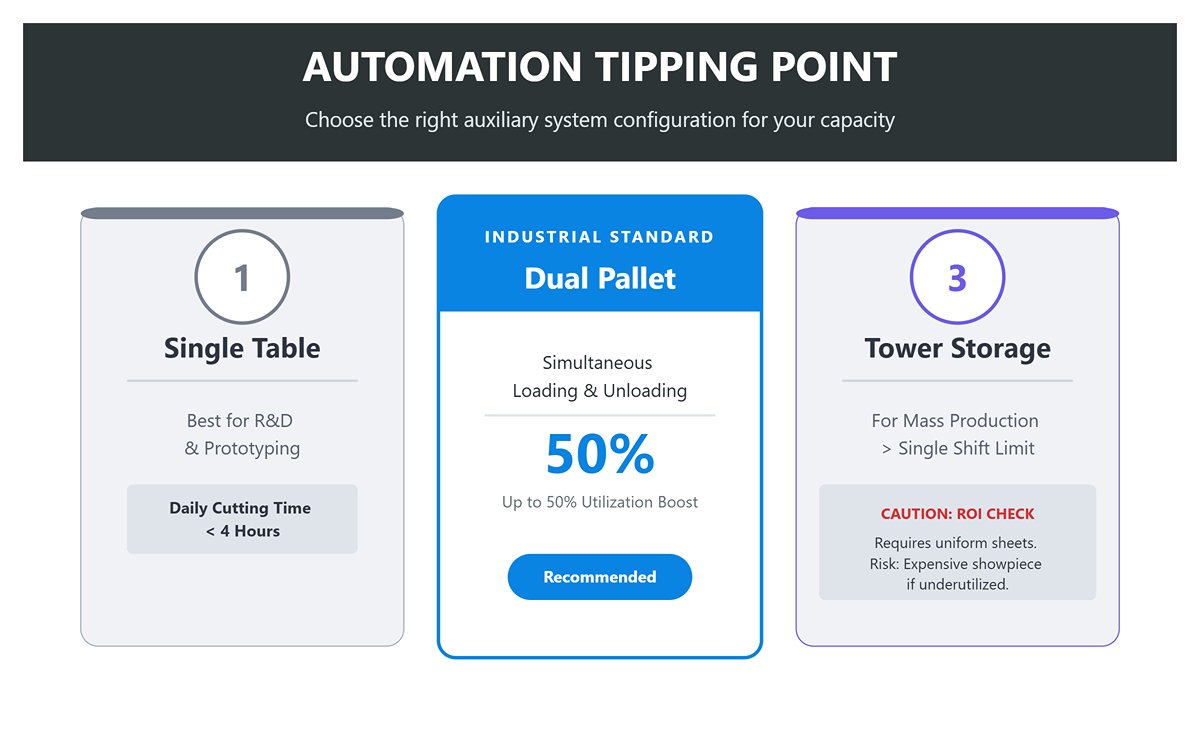
- Capacity Dimension: The Tipping Point for Automation This is what determines your auxiliary system configuration.
- Single table: Suitable for R&D, prototyping, or situations where daily cutting time is less than 4 hours.
- Dual pallet changer: The industrial standard. Uses cutting time to complete loading and unloading, boosting equipment utilization by 30%–50%.
- Automated tower storage: Only delivers a clear ROI when your daily output exceeds the limit of a single shift and sheet specifications are relatively uniform. Otherwise, it risks becoming an expensive showpiece.
3.2 The Economics of Balancing Power and Efficiency
A common misconception is that “doubling power = doubling efficiency,” but physics tells us that returns diminish at the margin.
- The Power Trap: Recognizing the Mechanical Ceiling
- Thin-sheet speed bottleneck: For 1–3 mm sheets, cutting speed is no longer limited by laser power but by the machine’s kinematics—acceleration (G value) and max contouring speed. Once you exceed roughly 6 kW, further gains in thin-sheet speed are minimal because the servo system cannot move faster without sacrificing accuracy. Investing in more power here is like driving a Ferrari in rush-hour downtown traffic.
- Thick-plate process bottleneck: For plates thicker than 20 mm, higher power does improve speed, but you must watch out for trading quality for speed. Excessive cutting speed can lead to rougher striations on the cut face and heavy dross at the bottom, and the extra grinding and rework can easily wipe out any profit gained from faster cutting.
- Threshold Analysis: Finding the Most Cost-effective Power Range
- 1–3 kW (Economy Range): Ideal entry-level choice for fast cutting of thin sheets, suited to signage, kitchenware, and enclosure industries, with very short payback periods.
- 6–12 kW (All-rounder): Currently the mainstream range. It covers efficient processing of medium and thick plate (6–25 mm) while still pushing the machine to its performance limits on thin sheets—making it the “universal” configuration for most job shops.
- 20 kW+ (Replacement Range): Targeted at markets traditionally served by plasma or oxy-fuel cutting (30–50 mm+). Unless you have stable, high-volume heavy-plate orders, you should be cautious about stepping into this high-investment segment.
- The Economics of Assist Gases: A Major Operating Cost You Can’t Ignore Gas costs must be considered alongside machine selection.
- Air cutting: Extremely low cost (electricity only), suitable for carbon steel where a dark cut surface is acceptable.
- Nitrogen cutting: Relatively expensive (gas charges plus cylinder rental or liquid tanks), but delivers a bright finish on stainless steel and aluminum, eliminating downstream polishing steps.
- Oxygen cutting: Essential for thick carbon steel. It uses an exothermic combustion reaction to boost cutting speed, but the cut edge will have an oxide layer.
- Recommendation: If your main work is stainless steel, investing in a high‑pressure air compressor (as a nitrogen substitute) often pays for itself within 6–12 months.
3.3 Pitfall Guide: The “Hidden Costs” You Won’t See on the Quotation
Low-priced machines usually rely on downgraded, unlisted configurations to preserve profit. These hidden compromises inevitably turn into long-term headaches for the buyer.
- Core component brands: Beware the maintenance nightmare of “Frankenstein” machines
Distinguishing between a fully integrated OEM machine and a “parts-assembled” unit is critical. Top-tier brands typically use self-developed or deeply customized cutting heads and control systems with tightly matched hardware and software. In contrast, low-cost assembled machines often pair generic low-end control cards with no-name cutting heads. When something goes wrong, troubleshooting is difficult, and hardware and software vendors frequently blame each other.
Selection rule of thumb: Whenever possible, choose a solution where the laser source, cutting head, and control system all come from the same brand ecosystem, or from a combination that has been extensively validated in the market.
- Machine bed treatment: The invisible process that determines service life
This is the backbone of long-term accuracy—and because you can’t see it with the naked eye, it’s also the easiest place for manufacturers to cut corners. A qualified laser cutting machine bed must undergo rigorous stress-relief annealing after welding, a process that is both costly and time-consuming. If the bed is not annealed, or only given a simple aging treatment, large residual welding stresses remain inside the structure. After 3–6 months of operation, vibrations gradually release these stresses, causing micron-level distortion that you can’t see but will feel: one side cuts through cleanly while the other side won’t cut through at all, and no amount of parameter tweaking can fully correct it.
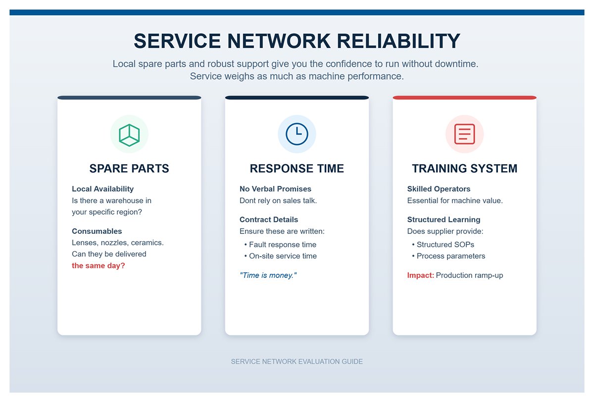
- Service network: The confidence that comes from local spare parts
For manufacturing companies, a single day of downtime can mean tens of thousands in losses. As a result, after-sales service should carry at least as much weight in your decision as machine performance.
- Spare parts inventory: Check whether the supplier has a local parts warehouse in your region. Can consumables (lenses, nozzles, ceramic bodies) be delivered the same day?
- Response time: Don’t rely on verbal promises. Make sure “fault response time” and “on-site service time” are written explicitly into the contract.
- Training system: A good machine still needs skilled operators. Does the supplier provide structured SOP training and process parameter packages? This directly determines how quickly your production ramps up after installation.
4. Process Excellence: Advanced Operating Guide for Solving Pain Points
Buying the machine is only your “ticket to enter.” Your real competitive moat in a cutthroat red-ocean market is process tuning capability. Many users own top-of-the-line hardware but, lacking deep process know-how, endure persistently low yield rates. This chapter walks you from basic “cutting through” to “perfect cutting,” revealing the practical techniques seasoned engineers rarely share.
4.1 Tackling the Tough Stuff: Special Materials and Thick Plates
Fear of highly reflective materials and frustration with rough thick-plate cutting usually come from misunderstandings of the underlying physics. Master the strategies below and you can turn these pain points into your own technical moat.
- Highly Reflective Metals (Copper/Aluminum/Gold/Silver): Building an “Optical Isolation” Defense Line
Copper and aluminum naturally reflect fiber laser light (1.064 μm wavelength) at very high levels. When the beam hits the metal surface vertically, as much as 30%–70% of the energy can bounce straight back along the beam path. This back reflection can easily damage the delivery fiber and the laser resonator.- Hardware Protection: When selecting a laser, you must confirm that it includes a multi‑stage anti‑reflection optical isolator. This works like an “optical diode” that only lets light pass one way, effectively absorbing back reflections and protecting core components.
- Process Strategy: Avoid low‑speed piercing. Use high‑speed piercing combined with negative defocus (focus shifted below the surface) to enlarge the spot and reduce power density at the surface, thereby lowering reflectivity risk. For pure copper, it is recommended to use oxygen assist gas so that the oxide layer formed on the surface reduces reflectance and increases laser absorption.
- Thick Carbon Steel: “Pulse Modulation” to Tame Heat Effects
For thick plates (20 mm and above), the two classic issues are corner overburn (erosion at corners) and hard slag at the bottom. At their core, both problems come from a mismatch between heat accumulation and slag removal over time.- Curing Overburn: Enable the CNC system’s power–speed coupling (power ramping) function. As the cutting head slows down approaching a sharp corner, the system automatically reduces laser power and frequency proportionally, lowering heat input. This prevents corners from overheating, melting, and rounding off, and keeps edges sharp.
- Eliminating Slag: Abandon continuous‑wave (CW) cutting and switch to a pulse mode with high peak power, low frequency, and high duty cycle. The high peak power acts like a “heavy hammer,” instantly punching through the material, while the off‑time between pulses allows the material to cool. Paired with an oxygen jet to blow out molten slag, you can achieve vertical cut faces that need no secondary grinding, at the cost of some cutting speed.
- Precision Micro‑holes: Pushing the Limits of Small-Hole Machining
When the hole diameter is smaller than the plate thickness (diameter‑to‑thickness ratio < 1:1), heat is difficult to dissipate. In this case, use soft piercing technology—very low pulse power to slowly melt through the material—so you avoid violent blow‑through. For dense arrays of small holes, apply a pre‑piercing strategy: first complete all piercings, then return to cut the contours. This gives the plate time to release heat and prevents thermal deformation.
4.2 Quality Diagnosis: Reading the Cut Face to Find the Root Cause
The cut surface is more than an appearance requirement; it is like an “ECG” of your machine’s condition. Once you learn to read its patterns, a single glance at the cut face lets you pinpoint system issues.
- Defect Map: A Three‑Dimension Diagnostic Logic
- Drag Lines: Observe the inclination of the striations on the cut surface. Ideally, they should be vertical to the plate. If the lines at the bottom trail strongly backward (large drag), it indicates cutting speed is too high or laser power has dropped, so the beam cannot fully cut through the material in time.
- Surface Roughness: A smooth upper section and rougher lower section is normal. But if deep grooves appear across the entire thickness, the likely causes are excessive gas pressure creating turbulent flow, or nozzle misalignment so the beam does not pass through the center of the gas stream.
- Bottom Slag Morphology:
- Loose Burrs: Foam‑like slag hanging at the bottom that flakes off easily. Root causes: focus too high or insufficient gas pressure.
- Hard Nodules: Solid, droplet‑shaped slag welded firmly to the underside and hard to remove. Root causes: focus too low, cutting speed too slow causing overmelting, or low gas purity.

- Quick Correction Reference Table
| Symptom | Root Cause | Action |
|---|---|---|
| Cut edge is black (stainless steel/aluminum) | Nitrogen purity below 99.99% | Replace the liquid nitrogen tank or check gas lines for leaks |
| Cut edge appears blue (carbon steel) | Oxygen pressure too high | Lower cutting pressure, fine‑tune in 0.1 bar steps |
| Slag difficult to remove (hard) | Focus too low or speed far too slow | Raise focus (+0.5 mm) and moderately increase feed rate |
| Slag easy to remove (loose) | Focus too high or gas pressure too low | Lower focus (−0.5 mm) and increase assist gas pressure |
| Arc cannot start / cannot cut through | Nozzle damaged or optical path misaligned | Replace nozzle and perform adhesive‑tape spot/coaxiality test |
| Corner burning/erosion | Heat accumulation at deceleration points | Enable corner power‑curve control or use a circular lead‑out/loop path |
4.3 Multiplying Efficiency: Using Advanced Software Functions
Hardware sets the lower bound of performance; how deeply you leverage software sets the upper bound. By using advanced CAM strategies, you can double throughput without spending a cent on additional hardware.
- Fly Cutting: “Light-Speed” Production for Perforated Sheets
When processing meshes, ventilation panels, or other dense patterns, the traditional cycle—cut, stop, lift, move, lower, pierce—often spends more time on non‑cutting moves than on actual cutting. Fly cutting (also called “scan cutting”) breaks this pattern. The laser head moves at high speed with the beam kept on, and a high‑speed shutter switches the laser on and off while in motion to complete all cuts. The motion is smooth, with almost no accelerate‑stop‑decelerate cycles, like a dragonfly skimming over water. For thin perforated sheets, efficiency gains of 300%–500% are achievable. - Common-Line and Skeleton‑Free Cutting: The Triumph of Minimalism
- Common-Line Cutting: For rectangular or other regular parts, the software automatically merges adjacent contours so a single cut edge serves two parts. This reduces total cutting path and dramatically cuts down the number of piercings—piercing being one of the most nozzle‑intensive steps.
- Skeleton‑Free Cutting: Traditional nesting leaves behind a large mesh‑like scrap skeleton that is hard to remove and prone to warping, which can scratch or collide with the cutting head. Advanced algorithms can segment scrap into small pieces or hold parts in place with micro‑joints so that the sheet remains flat; at unloading, a light tap is enough to separate parts. This eliminates heavy scrap‑cutting and handling work and is a key stepping stone toward fully automated sorting.
- Active Avoidance: The safety valve for lights-out operation In laser cutting, the costliest accidents usually come from the cutting head crashing into parts that have lifted or warped. The Active Avoidance function uses capacitive sensing or pre-calculated toolpaths to identify areas where cutting is already completed (and where parts are likely to spring up). When the head needs to cross these zones, the Z-axis automatically lifts to a safe height and “frog-jumps” over them, or intelligently reroutes the path. This feature is a core safety guarantee for truly unattended, overnight “lights-out factory” operation.
5. Operations & Maintenance System: A full-lifecycle asset management strategy
Purchasing the machine is essentially an asset swap; what really determines whether this asset can keep generating “compound interest” is the operations and maintenance system that follows. On the shop floor, we’ve seen far too many million‑dollar machines lose their accuracy within three years due to poor maintenance. This chapter moves away from the traditional “fix it when it breaks” mindset and builds a proactive asset management strategy based on Preventive Maintenance (PM) and Standard Operating Procedures (SOP). The goal is to drive failure rates as low as possible and keep cutting accuracy on day 1,000 as consistent as on day 1.
5.1 Standard Operating Procedures (SOP): Eliminating the human variable
More than 60% of equipment instability is caused by improper operator behavior. Strict SOPs are not about tying people’s hands; they are about building muscle memory and eliminating human variability.
- Startup ritual: An indispensable “three-step” sequence
Powering up should be more than just flipping a switch; it should be treated as a ritual that ensures the entire system is reset to a known state:- Homing: This is the only way to rebuild the machine’s mechanical coordinate system. You must wait until all X/Y/Z/W axes have fully returned to home to eliminate any mechanical drift that may have occurred while the power was off.
- Capacitance Calibration: The Z-axis following in laser cutting relies entirely on capacitive sensing. After startup or any nozzle change, you must run an automatic capacitance calibration so the head can accurately track sheet height variations in microseconds. This is the first line of defense against head collisions.
- Beam coaxiality self-check (Tape Shot): Don’t wait until you scrap a batch of parts to discover beam misalignment. After startup each day, the operator should perform a quick “tape shot” using transparent tape, then check whether the burn hole is exactly in the center of the nozzle orifice. A coaxiality error of just 0.5 mm is enough to turn a bright, clean cut into scrap metal.
- First-piece inspection: Closing the loop from dimensions to optics
First-piece triple inspection (self-check, peer check, and QC check) is not just about measuring length and width; it’s also about “reading” the cut face to understand the machine’s condition.- Dross pattern diagnosis: If the underside of the first part shows hard, undercut dross, don’t blindly tweak parameters. Check the protective window for contamination first.
- Micro-joint strength test: Gently wiggle the part by hand to confirm that the micro-joint can both hold the part flat and be broken off easily. If it’s too strong, downstream part removal costs go up; if it’s too weak, parts will tip over and trigger alarms.
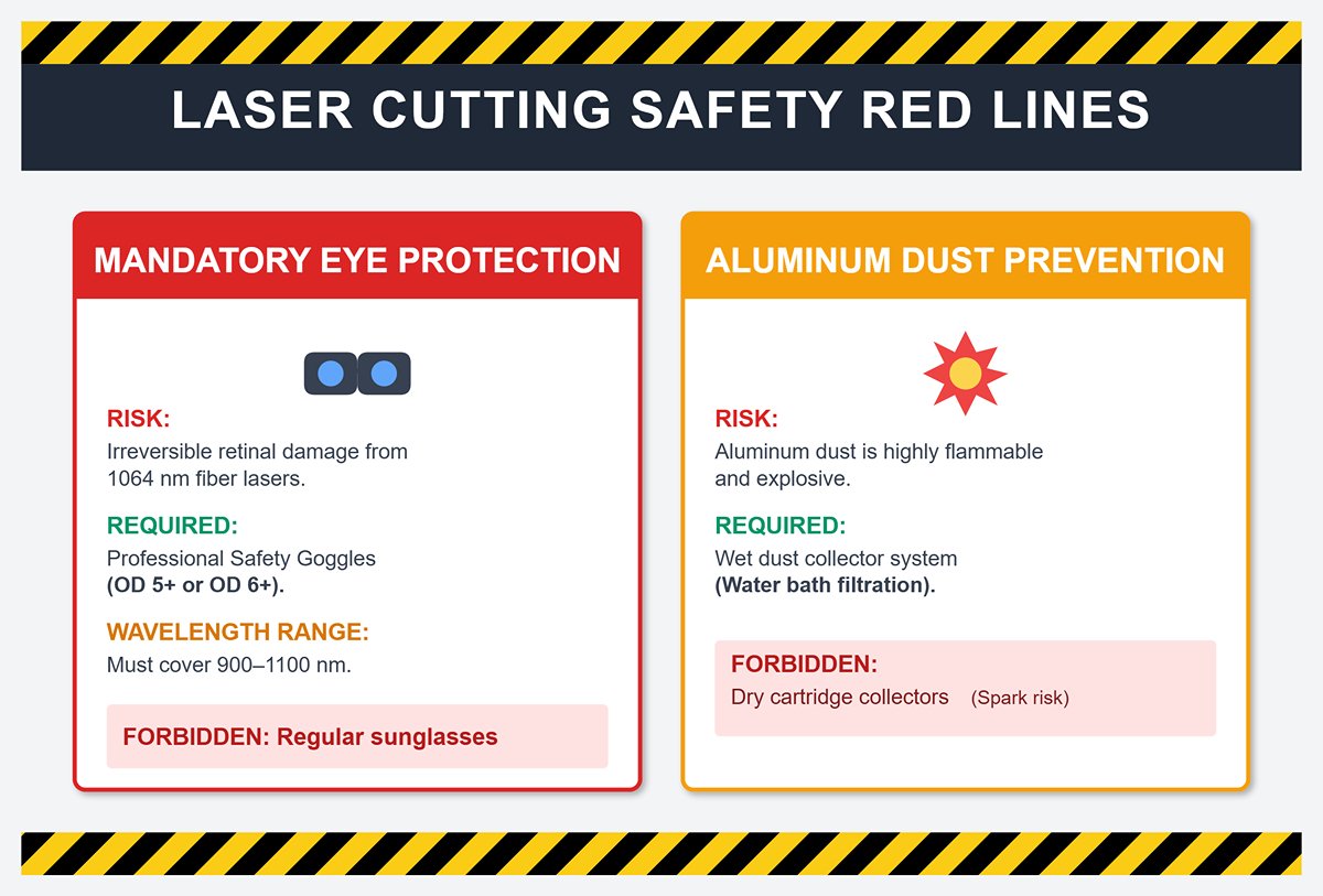
- Safety red lines: Cutting with your life on the line
The laser is invisible, but the danger is very real. You must establish non‑negotiable safety red lines:- Mandatory optical density (OD) standards: Regular sunglasses are strictly forbidden. Fiber lasers (1064 nm) can cause irreversible retinal damage. You must enforce the use of professional safety goggles rated at OD 5+ or OD 6+, covering the 900–1100 nm wavelength range.
- Aluminum dust explosion prevention: Dust from cutting aluminum alloys is an extremely flammable and explosive material. When processing aluminum, a wet dust collector (water bath filtration) is mandatory. Dry cartridge collectors are strictly prohibited to prevent hot sparks from igniting an aluminum dust cloud in the collection box.
5.2 Preventive Maintenance Calendar (PM): Small costs against big depreciation
The best repair is “no repair.” Scheduled interventions break the chain of fault progression. It’s recommended to put the following calendar on your shop floor visual boards.
- Daily: Optical cleanliness
- Protective window: This is the most frequently replaced consumable—and the “body armor” of the cutting head. Check the surface daily for any black spots. Remember: any speck visible to the naked eye will rapidly explode under high laser power, potentially destroying the much more expensive collimating or focusing lenses.
- Nozzle cleaning: Remove any spatter stuck to the nozzle tip to ensure an ideal gas jet profile.
- Weekly/Monthly: The lifeline of motion and cooling
- Drive lubrication (weekly): Check the level of the automatic lubrication pump. Gear racks must be evenly coated with oil; for linear guides, clean out the sludge in the corners of the way covers so it doesn’t turn into abrasive paste.
- Chiller “health check” (monthly): This is a commonly neglected blind spot. You need to check not just water level, but also water conductivity. Deionized water conductivity must be kept strictly below 10 μS/cm. Once conductivity exceeds this limit, electrochemical corrosion will occur inside the laser’s cooling channels, causing irreversible power degradation or even total failure.
- Annual overhaul: Resetting accuracy
- Geometric accuracy calibration: After a year of high‑frequency vibration, slight micron‑level changes in bed leveling and squareness are inevitable. We recommend hiring the OEM each year to use a laser interferometer for full‑stroke pitch error compensation, restoring the machine to near factory accuracy.
5.3 Fault prewarning and spare parts strategy: Designed for zero downtime
When a fault occurs, response time is everything. A well‑designed spare parts strategy and troubleshooting logic can minimize downtime losses.
- Spare parts model for wear items
Don’t wait until components fail to place an order. Build a tiered inventory strategy:- Consumables (grab-and-go): Nozzles, ceramic rings, and protective windows. It’s advisable to keep at least two weeks of safety stock.
- Strategic spares (critical backups): Focusing lens assemblies, sensing cables, and solenoid valves. These parts fail infrequently, but when they do, the machine goes down. Keep at least one complete backup set.

- Fast troubleshooting for common alarms
Equip operators with basic diagnostic skills to avoid long outages while waiting on the manufacturer.- Capacitance Error: Typically presents as erratic Z‑axis motion or loss of proper following.
- Recommended sequence: Check for dross on the nozzle → Check that the ceramic ring is firmly tightened → Check RF cable connections for looseness → Only then suspect issues with the calibration amplifier. In 90% of cases, the first two steps resolve the problem.
- Servo Alarm (overload): Most often occurs during high‑speed movements.
- Capacitance Error: Typically presents as erratic Z‑axis motion or loss of proper following.
- Troubleshooting sequence: check whether any foreign objects are jamming the linear guides → check whether any serious collisions have caused mechanical deformation → check whether the coupling is loose.
By building this operations and maintenance system, we turn equipment from a “consumable” into a “controllable asset.” A properly maintained laser cutting machine can still hold a cutting accuracy of ±0.05 mm even after 5–7 years of service—and that precision is the physical foundation of a company’s long-term competitiveness.
Ⅶ. Conclusion
This article provides a comprehensive analysis of laser cutting technology, starting from the microscopic principles of high-energy photon excitation, focusing, and interaction with materials. It breaks down how core subsystems—such as the laser source, optical path, cutting head, drive mechanisms, and CNC control—work in concert to precisely transform digital blueprints into physical objects. The seamless integration of these elements is what defines a high-performance Laser Cutting Machine.
Laser cutting has evolved beyond a mere cutting tool; it represents a profound revolution in manufacturing paradigms, acting as a vital bridge between digital design and high-precision production. Its sub-millimeter accuracy, smooth cut surfaces, minimal heat-affected zones, and ability to tackle intricate contours have ushered in unprecedented design freedom and production agility in modern industry. Today, it stands as a foundational technology in areas ranging from sheet metal fabrication and automotive manufacturing to aerospace and precision medical applications. This versatility is further enhanced in models like the Dual-use Fiber Laser Cutting Machine, which can handle both metal sheets and tubes with equal precision.
As such, adopting laser cutting technology is an inevitable step for companies aiming to upgrade their operations. However, successful implementation is a strategic investment that demands careful planning: before making decisions, it is essential to clearly define the core materials and thickness ranges to be processed, evaluate production volumes, efficiency targets, and automation potential, and thoroughly consider initial investment, operating costs, and long-term maintenance. Only by precisely aligning technology selection with specific business needs can enterprises fully unlock the cost-saving and efficiency-enhancing potential of laser cutting. To ensure you make the right choice for your business, we invite you to contact us for personalized guidance from our experts. For a foundational understanding, you can also read CNC Laser Cutting Machines Explained.


